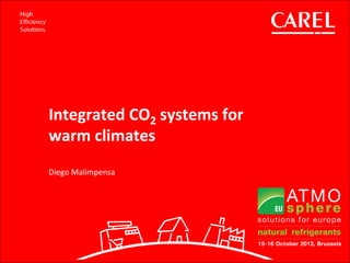

![How to divide total energy consumption between REF – AC – HR?
Compressor power consumption [kW]
• PMT : Medium temperature compressors
• PLT : Low temperature compressors
• PPC : Parallel compressors
• PGC : Gas cooler
Integration
Heat transfer
• QAC : Air conditioning heat
• QHR : Heat recovery heat
One unit providing REF+AC+HR](https://image.slidesharecdn.com/atmoeu2013-carel-malimpensa-160906081720/85/Integrated-CO2-systems-for-warm-climates-5-320.jpg)

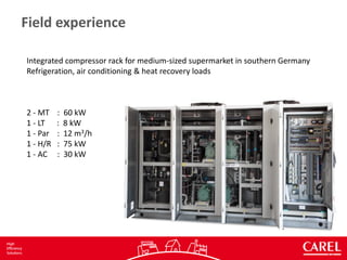
![Integration
Temperatures
Pressures
Comps data
Entalpies
Qualities
COPHR
COPAC
COPREF
PHR PAC
PREF
Air conditioning mode
Heat Reclaim mode
Higher gas cooler pressure
Higher quality of vapour
𝐶𝑂𝑃 𝐻𝑅 𝑂𝑁
𝐶𝑂𝑃 𝐻𝑅 𝑂𝐹𝐹 [𝑇]
=
𝑃 𝐻𝑅 𝑂𝑁
𝑃 𝐻𝑅 𝑂𝐹𝐹
Higher quality of vapour
Mass refrigerant flow 𝑚 𝐴𝐶](https://image.slidesharecdn.com/atmoeu2013-carel-malimpensa-160906081720/85/Integrated-CO2-systems-for-warm-climates-7-320.jpg)
![00
10
20
30
40
50
60
10 11 12 13 14 15 16 17 18 19 20 21 22 23 24 25 26 27 28 29 30 31 32 33 34 35
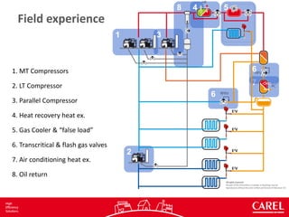
PowerConsumption[kW]
Outside temperature [°C]
Power consumption vs Temperature
Booster with Flash Valve Booster with Parallel compressor
Parallel compressor
enabled to run only when
outside temperature higher
than 15°C
Warm Climates
-15%](https://image.slidesharecdn.com/atmoeu2013-carel-malimpensa-160906081720/85/Integrated-CO2-systems-for-warm-climates-9-320.jpg)
![0
20
40
60
80
100
120
140
160
180
200
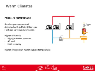
Munich [8°C] Venice [13°C] Palermo [18°C]
PowerConnsumption[kW]
Energy consumption comparison
Booster with Flash Valve Booster with Parallel Comp
-4%
-10%
Warm Climates
-7%](https://image.slidesharecdn.com/atmoeu2013-carel-malimpensa-160906081720/85/Integrated-CO2-systems-for-warm-climates-10-320.jpg)
![0
20
40
60
80
100
120
140
160
180
200
Munich [8°C] Venice [13°C] Palermo [18°C]
PowerConnsumption[kW]
Energy consumption comparison
Booster with Flash Valve Cascade R134a/CO2 Booster with Parallel Comp
Warm Climates
-10%
-6%
≈](https://image.slidesharecdn.com/atmoeu2013-carel-malimpensa-160906081720/85/Integrated-CO2-systems-for-warm-climates-11-320.jpg)


This document discusses an integrated CO2 system for refrigeration, air conditioning, and heat recovery installed in a supermarket in southern Germany. It includes: 1. Medium and low temperature compressors, a parallel compressor, heat exchangers, and valves to control the transcritical and flash gas processes. 2. The system is controlled as a single unit to reduce installation costs and space needs while improving efficiency through more precise control and optimization of refrigeration, air conditioning, and heat recovery loads. 3. Data is collected in real-time to calculate COP and divide total energy consumption between the different applications to evaluate system performance under varying operating conditions.


