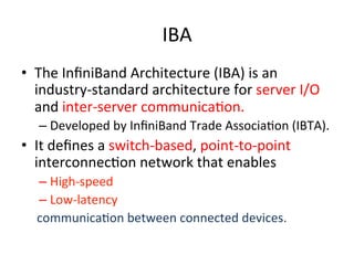
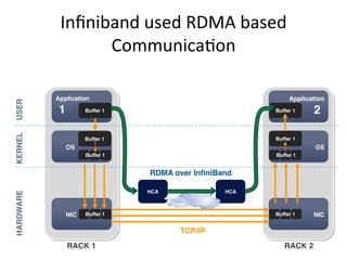
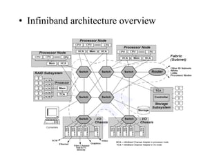
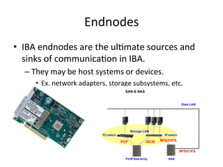
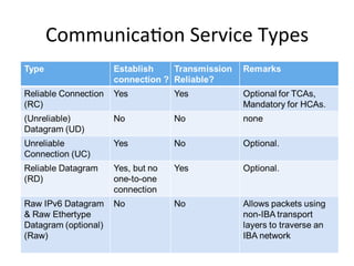
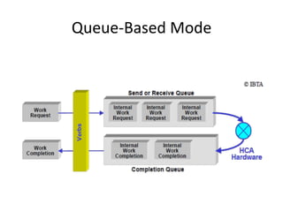
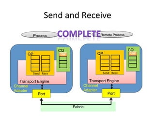
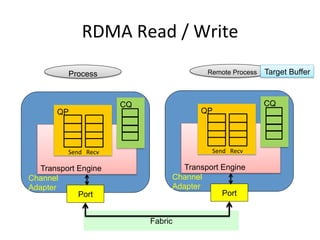
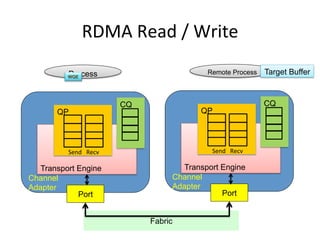
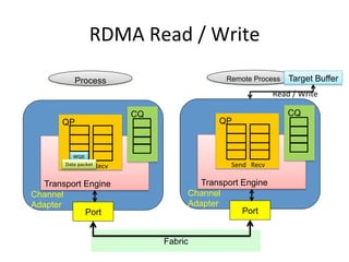
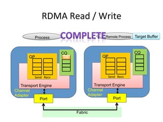
HPC networks: Infiniband
IBA
• The InfiniBand Architecture (IBA) is an
industry-standard architecture for server I/O
and inter-server communicaCon.
– Developed by InfiniBand Trade AssociaCon (IBTA).
• It defines a switch-based, point-to-point
interconnecCon network that enables
– High-speed
– Low-latency
communicaCon between connected devices.
Infiniband used RDMA based
CommunicaCon
Mellanox Training Center Training Material
RDMA – How Does it Work
RDMA over InfiniBand
KERNEL
HARDWARE
USER
RACK 1
OS
NIC Buffer 1
Application
1
Application
2
OS
Buffer 1
NIC
Buffer 1
TCP/IP
RACK 2
HCA HCA
Buffer 1
Buffer 1
Buffer 1
Buffer 1
Buffer 1
• Infiniband architecture overview
Mellanox Training Center 46
Training Material
IB Architecture Layers
Software Transport Verbs and Upper Layer Protocols:
- Interface between application programs and hardware.
- Allows support of legacy protocols such as TCP/IP
- Defines methodology for management functions
Physical:
- Signal levels and frequency, media, connectors
Transport:
- Delivers packets to the appropriate Queue Pair;
Message Assembly/De-assembly, access rights, etc.
Data Link (symbols and framing):
- From source to destination on the same partition subnet
Flow control (credit-based); How packets are routed
Network:
- How packets are routed between different partitions/subnets
Client
Transactions
Messages
Que Pairs
Inter Subnet Routing
End Node Switch L2 End Node
L2 Switching LID Based
Client
IBA
Operations
SAR
IBA
Operations
SAR
Network Network
Link
Encoding
Media
Access
Control
Link
Encoding
Media
Access
Control
Packet
Relay
MAC
MAC
Architecture Layers
InfiniBand VS. Ethernet
Ethernet InfiniBand
Commonly used in
what kinds of
network
Local area network(LAN)
or
wide area network(WAN)
Interprocess
communicaCon (IPC)
network
Transmission medium Copper/opCcal Copper/opCcal
Bandwidth 1Gb/10Gb 2.5Gb~120Gb
Latency High Low
Popularity High Low
Cost Low High
InfiniBand Devices
Host Channel Adapter (HCA)
• Device that terminates an IB link and
executes transport-level functions and
support the verbs interface
Switch
• A device that moves packets from one
link to another of the same IB Subnet
Router
• A device that transports packets
between different IBA subnets
Bridge/Gateway
• InfiniBand to Ethernet
InfiniBand Components Overview
IBA Subnet
Endnodes
• IBA endnodes are the ulCmate sources and
sinks of communicaCon in IBA.
– They may be host systems or devices.
• Ex. network adapters, storage subsystems, etc.
Links
• IBA links are bidirecConal point-to-point
communicaCon channels, and may be either
copper and opCcal fibre.
– The base signalling rate on all links is 2.5 Gbaud.
• Link widths are 1X, 4X, and 12X.
Channel Adapter
• Channel Adapter (CA) is the interface between
an endnode and a link
• There are two types of channel adapters
– Host channel adapter(HCA)
• For inter-server communicaCon
• Has a collecCon of features that are defined to be
available to host programs, defined by verbs
– Target channel adapter(TCA)
• For server IO communicaCon
• No defined soware interface
Addressing
• LIDs
– Local IdenCfiers, 16 bits
– Used within a subnet by switch for rouCng
– Dynamically assigned at runCme
• GUIDs
– Global Unique IdenCfier
– Assigned by vendor (just like a MAC address)
– 64 EUI-64 IEEE-defined idenCfiers for elements in a subnet
• GIDs
– Global IDs, 128 bits (same format as IPv6)
– Used for rouCng across subnets
GID: RouCng across subnets
Mellanox Training Center 18
Training Material
Usage
• A 128 bit field in the Global Routing Header (GRH) used to route packets between different IB
subnets
• Multicast groups port identifier IB & IPOIB
Structure
• GUID- 64 bit identifier provided by the manufacturer
• IPv6 type header
• Subnet Prefix: A 0 to 64-bit:
- Identifier used to uniquely identify a set of end-ports which are managed by a common Subnet
Manager
GID - Global Identifier
port GUID: 0x0002c90300455fd1
fe80:0000:0000:0x0002c90300455fd1
default gid:
Switches
• IBA switches route messages from their source to their
desCnaCon based on rouCng tables
– Configured explicitly by Subnet Manager
• Switch size denotes the number of ports
– The maximum switch size supported is one with 256 ports
• The addressing used by switches
– Local IdenCfiers, or LIDs allows 48K endnodes on a single
subnet
– A 64K LID address region is reserved for mulCcast
addresses
– RouCng between different subnets is done on the basis of
a Global IdenCfier (GID) that is 128 bits long
Management Basics
Mellanox Training Center 19
Training Material
Node: any managed entity– End Node, Switch, Router
Manager: active entity; sources commands and queries
• The subnet manager (SM)
Agent: passive (mostly) entity that will reside on every node, responds to Subnet Managers queries
Management Datagram (MAD):
• Standard message format for manager–agent communication
• Carried in an unreliable datagram (UD)
IB Basic Management Concepts
Agent
Agent
Agent
Agent
Agent
Agent
Agent
Agent
Subnet Manager
Mellanox Training Center 26
Training Material
Subnet Manager (SM) Rules & Roles
Every subnet must have at least one
- Manages all elements in the IB fabric
- Discover subnet topology
- Assign LIDs to devices
- Calculate and program switch chip forwarding tables (LFT pathing)
- Monitor changes in subnet
Implemented anywhere in the fabric
- Node, Switch, Specialized device
No more than one active SM allowed
- 1 Active (Master) and remaining are Standby (HA)
Subnet Management
• Subnet Manager:
– External soware service running on an endhost or switch
– OpenSM – most commonly used
– Assigns Addresses to endhosts and switches
– Directly configures rouCng tables in each switch and device
Management Datagrams
• All management is performed in-band, using
Management Datagrams (MADs).
– MADs are unreliable datagrams with 256 bytes of
data (minimum MTU).
• Subnet Management Packets (SMP) are special
MADs for subnet management.
– Only packets allowed on virtual lane 15 (VL15).
– Always sent and receive on Queue Pair 0 of each port
Infiniband rouCng
12
Infiniband Routing On a Healthy Subnet
Destination-Based Routing & Credit Based Flow Control
0x0001
0x0009
0x0013
0x0017
0x0021
0x0025
0x0013
Packet
0x0009
Destination LID
compared to Current LID
=
Consult Routing Table
Find Port for Dest. LID
Request for Buffer
Space Availability
Destination
Reached
No
Yes
Wait for Credits
Send
Packet
Infiniband RouCng
Mellanox Training Center 32
Training Material
Linear Forwarding Table Establishment (Path Establishment)
After the SM finished gathering
all Fabric information , including direct route tables ,
it assigns a LID to each one of the NODES
At this stage the LMX table will be populated with the relevant route
options to each one of the nodes
The output of the LMX will provide the Best Route
to Reach a DLID as well as the other Routes .
The Best Path Result Will be based on Shortest Path First (SPF)
algorithm
21 1 2 3 1
22 2 1 2 1
23 3 2 1 1
75 3 2 3 2
81 4 3 4 3
82 4 3 2 2
The
Dest.
LID
Best
Route/
exit
port
21 2
22 3
23 8
75 3
81 3
82 8
D-LID
PORT
LID 3
LID 21 LID 22 LID 23
LID 72 LID 75 LID 82
LID 81
Infiniband Packet Format
Mellanox Training Center Training Material
LRH: Local Routing Header :
• Source & Destination LID
• Service Level-SL
• Virtual Lane-VL
• Packet Length
LID Routed (LR) Forwarding
LFT Switch_1
The
Dest.
LID
Best
Route/
exit
port
21 2
22 3
23 8
75 3
81 3
82 8
LRH GRH BTH Ext
HDRs
Playload ICRC VCRC
InfiniBand Data Packet
8B 40B 12B Var 0…4096B 4B 2B
• GRH: Global RouCng Header
• Routes between subnets
• BTH: Base Transport Header
• Processed by endnodes
• ICRC: Invariant CRC
• CRC over fields that don’t change
• VCRC: Variant CRC
• CRC over fields that can change
CommunicaCon Service Types
Data Rate
• EffecCve theoreCcal throughput
Queue-Based Model
• Channel adapters communicate using Work
Queues of three types:
– Queue Pair(QP) consists of
• Send queue
• Receive queue
– Work Queue Request (WQR) contains the
communicaCon instrucCon
• It would be submihed to QP.
– CompleCon Queues (CQs) use CompleCon Queue
Entries (CQEs) to report the compleCon of the
communicaCon
Queue-Based Mode
Access Model for InfiniBand
• Privileged Access
– OS involved
– Resource management and memory management
• Open HCA, create queue-pairs, register memory, etc.
• Direct Access
– Can be done directly in user space (OS-bypass)
– Queue-pair access
• Post send/receive/RDMA descriptors.
– CQ polling
Access Model for InfiniBand
• Queue pair access has two phases
– IniCalizaCon (privileged access)
• Map doorbell page (User Access Region)
• Allocate and register QP buffers
• Create QP
– CommunicaCon (direct access)
• Put WQR in QP buffer.
• Write to doorbell page.
– NoCfy channel adapter to work
Access Model for InfiniBand
• CQ Polling has two phases
– IniCalizaCon (privileged access)
• Allocate and register CQ buffer
• Create CQ
– CommunicaCon steps (direct access)
• Poll on CQ buffer for new compleCon entry
Memory Model
• Control of memory access by and through an HCA is provided
by three objects
– Memory regions
• Provide the basic mapping required to operate with virtual
address
• Have R_key for remote HCA to access system memory and
L_key for local HCA to access local memory.
– Memory windows
• Specify a conCguous virtual memory segment with byte
granularity
– ProtecCon domains
• Ahach QPs to memory regions and windows
• InfiniBand creates a channel directly connec2ng an
applica2on in its virtual address space to an applica2on in
another virtual address space.
• The two applica2ons can be in disjoint physical address
spaces – hosted by different servers.
CommunicaCon SemanCcs
• Two types of communicaCon semanCcs
– Channel semanCcs
• With tradiConal send/receive operaCons.
– Memory semanCcs
• With RDMA operaCons.
Send and Receive
Transport Engine
Channel
Adapter
QP
Send Recv
CQ
Port
Transport Engine
Channel
Adapter
QP
Send Recv
CQ
Port
Remote Process
Process
Fabric
WQE
Send and Receive
Transport Engine
Channel
Adapter
QP
Send Recv
CQ
Port
Transport Engine
Channel
Adapter
QP
Send Recv
CQ
Port
Remote Process
Process
WQE
Fabric
WQE
Send and Receive
Transport Engine
Channel
Adapter
QP
Send Recv
CQ
Port
Transport Engine
Channel
Adapter
QP
Send Recv
CQ
Port
WQE
Remote Process
Process
Fabric
WQE
Data packet
Remote Process
Process
Send and Receive
Transport Engine
Channel
Adapter
QP
Send Recv
CQ
Port
Transport Engine
Channel
Adapter
QP
Send Recv
CQ
Port
CQE
CQE
Fabric
RDMA Read / Write
Transport Engine
Channel
Adapter
QP
Send Recv
CQ
Port
Transport Engine
Channel
Adapter
QP
Send Recv
CQ
Port
Remote Process
Process
Fabric
Target Buffer
RDMA Read / Write
Transport Engine
Channel
Adapter
QP
Send Recv
CQ
Port
Transport Engine
Channel
Adapter
QP
Send Recv
CQ
Port
Remote Process
Process
WQE
Fabric
Target Buffer
RDMA Read / Write
Transport Engine
Channel
Adapter
QP
Send Recv
CQ
Port
Transport Engine
Channel
Adapter
QP
Send Recv
CQ
Port
WQE
Remote Process
Process
Fabric
Data packet
Target Buffer
Read / Write
RDMA Read / Write
Transport Engine
Channel
Adapter
QP
Send Recv
CQ
Port
Transport Engine
Channel
Adapter
QP
Send Recv
CQ
Port
Remote Process
Process
CQE
Fabric
Target Buffer

infiniband.pdf

  • 1.
  • 2.
    IBA • The InfiniBandArchitecture (IBA) is an industry-standard architecture for server I/O and inter-server communicaCon. – Developed by InfiniBand Trade AssociaCon (IBTA). • It defines a switch-based, point-to-point interconnecCon network that enables – High-speed – Low-latency communicaCon between connected devices.
  • 3.
    Infiniband used RDMAbased CommunicaCon Mellanox Training Center Training Material RDMA – How Does it Work RDMA over InfiniBand KERNEL HARDWARE USER RACK 1 OS NIC Buffer 1 Application 1 Application 2 OS Buffer 1 NIC Buffer 1 TCP/IP RACK 2 HCA HCA Buffer 1 Buffer 1 Buffer 1 Buffer 1 Buffer 1
  • 4.
  • 5.
    Mellanox Training Center46 Training Material IB Architecture Layers Software Transport Verbs and Upper Layer Protocols: - Interface between application programs and hardware. - Allows support of legacy protocols such as TCP/IP - Defines methodology for management functions Physical: - Signal levels and frequency, media, connectors Transport: - Delivers packets to the appropriate Queue Pair; Message Assembly/De-assembly, access rights, etc. Data Link (symbols and framing): - From source to destination on the same partition subnet Flow control (credit-based); How packets are routed Network: - How packets are routed between different partitions/subnets Client Transactions Messages Que Pairs Inter Subnet Routing End Node Switch L2 End Node L2 Switching LID Based Client IBA Operations SAR IBA Operations SAR Network Network Link Encoding Media Access Control Link Encoding Media Access Control Packet Relay MAC MAC Architecture Layers
  • 6.
    InfiniBand VS. Ethernet EthernetInfiniBand Commonly used in what kinds of network Local area network(LAN) or wide area network(WAN) Interprocess communicaCon (IPC) network Transmission medium Copper/opCcal Copper/opCcal Bandwidth 1Gb/10Gb 2.5Gb~120Gb Latency High Low Popularity High Low Cost Low High
  • 7.
    InfiniBand Devices Host ChannelAdapter (HCA) • Device that terminates an IB link and executes transport-level functions and support the verbs interface Switch • A device that moves packets from one link to another of the same IB Subnet Router • A device that transports packets between different IBA subnets Bridge/Gateway • InfiniBand to Ethernet InfiniBand Components Overview
  • 8.
  • 9.
    Endnodes • IBA endnodesare the ulCmate sources and sinks of communicaCon in IBA. – They may be host systems or devices. • Ex. network adapters, storage subsystems, etc.
  • 10.
    Links • IBA linksare bidirecConal point-to-point communicaCon channels, and may be either copper and opCcal fibre. – The base signalling rate on all links is 2.5 Gbaud. • Link widths are 1X, 4X, and 12X.
  • 11.
    Channel Adapter • ChannelAdapter (CA) is the interface between an endnode and a link • There are two types of channel adapters – Host channel adapter(HCA) • For inter-server communicaCon • Has a collecCon of features that are defined to be available to host programs, defined by verbs – Target channel adapter(TCA) • For server IO communicaCon • No defined soware interface
  • 12.
    Addressing • LIDs – LocalIdenCfiers, 16 bits – Used within a subnet by switch for rouCng – Dynamically assigned at runCme • GUIDs – Global Unique IdenCfier – Assigned by vendor (just like a MAC address) – 64 EUI-64 IEEE-defined idenCfiers for elements in a subnet • GIDs – Global IDs, 128 bits (same format as IPv6) – Used for rouCng across subnets
  • 13.
    GID: RouCng acrosssubnets Mellanox Training Center 18 Training Material Usage • A 128 bit field in the Global Routing Header (GRH) used to route packets between different IB subnets • Multicast groups port identifier IB & IPOIB Structure • GUID- 64 bit identifier provided by the manufacturer • IPv6 type header • Subnet Prefix: A 0 to 64-bit: - Identifier used to uniquely identify a set of end-ports which are managed by a common Subnet Manager GID - Global Identifier port GUID: 0x0002c90300455fd1 fe80:0000:0000:0x0002c90300455fd1 default gid:
  • 14.
    Switches • IBA switchesroute messages from their source to their desCnaCon based on rouCng tables – Configured explicitly by Subnet Manager • Switch size denotes the number of ports – The maximum switch size supported is one with 256 ports • The addressing used by switches – Local IdenCfiers, or LIDs allows 48K endnodes on a single subnet – A 64K LID address region is reserved for mulCcast addresses – RouCng between different subnets is done on the basis of a Global IdenCfier (GID) that is 128 bits long
  • 15.
    Management Basics Mellanox TrainingCenter 19 Training Material Node: any managed entity– End Node, Switch, Router Manager: active entity; sources commands and queries • The subnet manager (SM) Agent: passive (mostly) entity that will reside on every node, responds to Subnet Managers queries Management Datagram (MAD): • Standard message format for manager–agent communication • Carried in an unreliable datagram (UD) IB Basic Management Concepts Agent Agent Agent Agent Agent Agent Agent Agent
  • 16.
    Subnet Manager Mellanox TrainingCenter 26 Training Material Subnet Manager (SM) Rules & Roles Every subnet must have at least one - Manages all elements in the IB fabric - Discover subnet topology - Assign LIDs to devices - Calculate and program switch chip forwarding tables (LFT pathing) - Monitor changes in subnet Implemented anywhere in the fabric - Node, Switch, Specialized device No more than one active SM allowed - 1 Active (Master) and remaining are Standby (HA)
  • 17.
    Subnet Management • SubnetManager: – External soware service running on an endhost or switch – OpenSM – most commonly used – Assigns Addresses to endhosts and switches – Directly configures rouCng tables in each switch and device
  • 18.
    Management Datagrams • Allmanagement is performed in-band, using Management Datagrams (MADs). – MADs are unreliable datagrams with 256 bytes of data (minimum MTU). • Subnet Management Packets (SMP) are special MADs for subnet management. – Only packets allowed on virtual lane 15 (VL15). – Always sent and receive on Queue Pair 0 of each port
  • 19.
    Infiniband rouCng 12 Infiniband RoutingOn a Healthy Subnet Destination-Based Routing & Credit Based Flow Control 0x0001 0x0009 0x0013 0x0017 0x0021 0x0025 0x0013 Packet 0x0009 Destination LID compared to Current LID = Consult Routing Table Find Port for Dest. LID Request for Buffer Space Availability Destination Reached No Yes Wait for Credits Send Packet
  • 20.
    Infiniband RouCng Mellanox TrainingCenter 32 Training Material Linear Forwarding Table Establishment (Path Establishment) After the SM finished gathering all Fabric information , including direct route tables , it assigns a LID to each one of the NODES At this stage the LMX table will be populated with the relevant route options to each one of the nodes The output of the LMX will provide the Best Route to Reach a DLID as well as the other Routes . The Best Path Result Will be based on Shortest Path First (SPF) algorithm 21 1 2 3 1 22 2 1 2 1 23 3 2 1 1 75 3 2 3 2 81 4 3 4 3 82 4 3 2 2 The Dest. LID Best Route/ exit port 21 2 22 3 23 8 75 3 81 3 82 8 D-LID PORT LID 3 LID 21 LID 22 LID 23 LID 72 LID 75 LID 82 LID 81
  • 21.
    Infiniband Packet Format MellanoxTraining Center Training Material LRH: Local Routing Header : • Source & Destination LID • Service Level-SL • Virtual Lane-VL • Packet Length LID Routed (LR) Forwarding LFT Switch_1 The Dest. LID Best Route/ exit port 21 2 22 3 23 8 75 3 81 3 82 8 LRH GRH BTH Ext HDRs Playload ICRC VCRC InfiniBand Data Packet 8B 40B 12B Var 0…4096B 4B 2B • GRH: Global RouCng Header • Routes between subnets • BTH: Base Transport Header • Processed by endnodes • ICRC: Invariant CRC • CRC over fields that don’t change • VCRC: Variant CRC • CRC over fields that can change
  • 22.
  • 23.
    Data Rate • EffecCvetheoreCcal throughput
  • 24.
    Queue-Based Model • Channeladapters communicate using Work Queues of three types: – Queue Pair(QP) consists of • Send queue • Receive queue – Work Queue Request (WQR) contains the communicaCon instrucCon • It would be submihed to QP. – CompleCon Queues (CQs) use CompleCon Queue Entries (CQEs) to report the compleCon of the communicaCon
  • 25.
  • 26.
    Access Model forInfiniBand • Privileged Access – OS involved – Resource management and memory management • Open HCA, create queue-pairs, register memory, etc. • Direct Access – Can be done directly in user space (OS-bypass) – Queue-pair access • Post send/receive/RDMA descriptors. – CQ polling
  • 27.
    Access Model forInfiniBand • Queue pair access has two phases – IniCalizaCon (privileged access) • Map doorbell page (User Access Region) • Allocate and register QP buffers • Create QP – CommunicaCon (direct access) • Put WQR in QP buffer. • Write to doorbell page. – NoCfy channel adapter to work
  • 28.
    Access Model forInfiniBand • CQ Polling has two phases – IniCalizaCon (privileged access) • Allocate and register CQ buffer • Create CQ – CommunicaCon steps (direct access) • Poll on CQ buffer for new compleCon entry
  • 29.
    Memory Model • Controlof memory access by and through an HCA is provided by three objects – Memory regions • Provide the basic mapping required to operate with virtual address • Have R_key for remote HCA to access system memory and L_key for local HCA to access local memory. – Memory windows • Specify a conCguous virtual memory segment with byte granularity – ProtecCon domains • Ahach QPs to memory regions and windows
  • 30.
    • InfiniBand createsa channel directly connec2ng an applica2on in its virtual address space to an applica2on in another virtual address space. • The two applica2ons can be in disjoint physical address spaces – hosted by different servers.
  • 31.
    CommunicaCon SemanCcs • Twotypes of communicaCon semanCcs – Channel semanCcs • With tradiConal send/receive operaCons. – Memory semanCcs • With RDMA operaCons.
  • 32.
    Send and Receive TransportEngine Channel Adapter QP Send Recv CQ Port Transport Engine Channel Adapter QP Send Recv CQ Port Remote Process Process Fabric WQE
  • 33.
    Send and Receive TransportEngine Channel Adapter QP Send Recv CQ Port Transport Engine Channel Adapter QP Send Recv CQ Port Remote Process Process WQE Fabric WQE
  • 34.
    Send and Receive TransportEngine Channel Adapter QP Send Recv CQ Port Transport Engine Channel Adapter QP Send Recv CQ Port WQE Remote Process Process Fabric WQE Data packet
  • 35.
    Remote Process Process Send andReceive Transport Engine Channel Adapter QP Send Recv CQ Port Transport Engine Channel Adapter QP Send Recv CQ Port CQE CQE Fabric
  • 36.
    RDMA Read /Write Transport Engine Channel Adapter QP Send Recv CQ Port Transport Engine Channel Adapter QP Send Recv CQ Port Remote Process Process Fabric Target Buffer
  • 37.
    RDMA Read /Write Transport Engine Channel Adapter QP Send Recv CQ Port Transport Engine Channel Adapter QP Send Recv CQ Port Remote Process Process WQE Fabric Target Buffer
  • 38.
    RDMA Read /Write Transport Engine Channel Adapter QP Send Recv CQ Port Transport Engine Channel Adapter QP Send Recv CQ Port WQE Remote Process Process Fabric Data packet Target Buffer Read / Write
  • 39.
    RDMA Read /Write Transport Engine Channel Adapter QP Send Recv CQ Port Transport Engine Channel Adapter QP Send Recv CQ Port Remote Process Process CQE Fabric Target Buffer