Download as PDF, PPTX


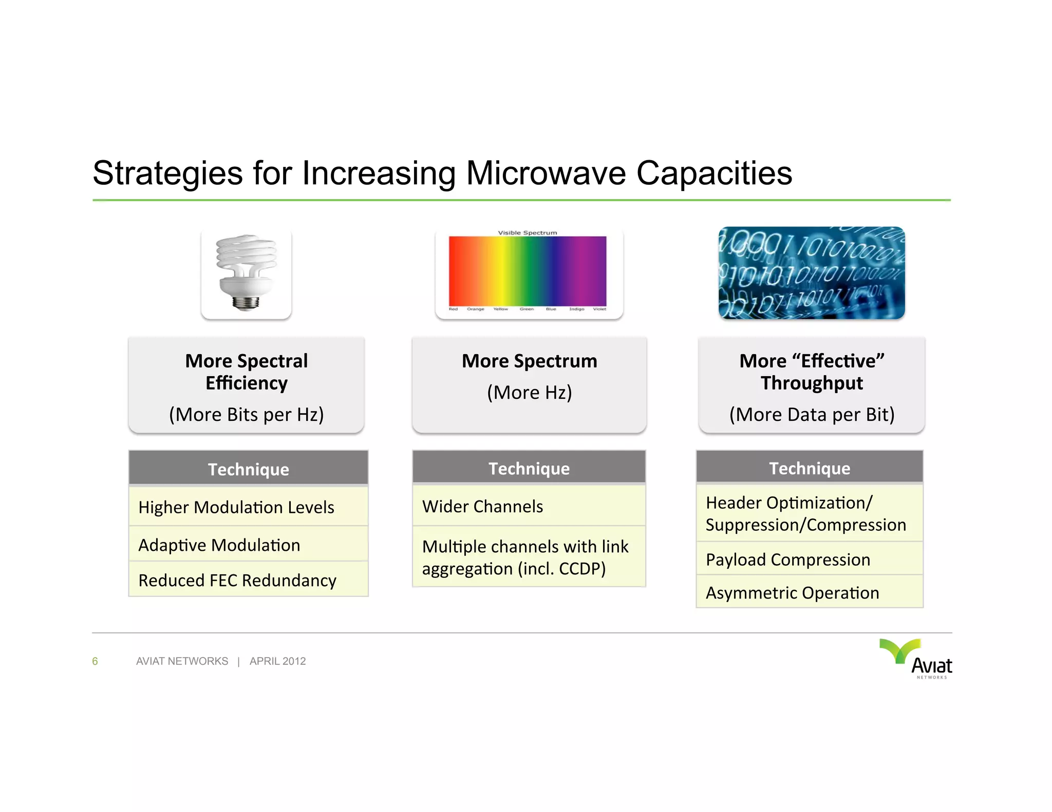

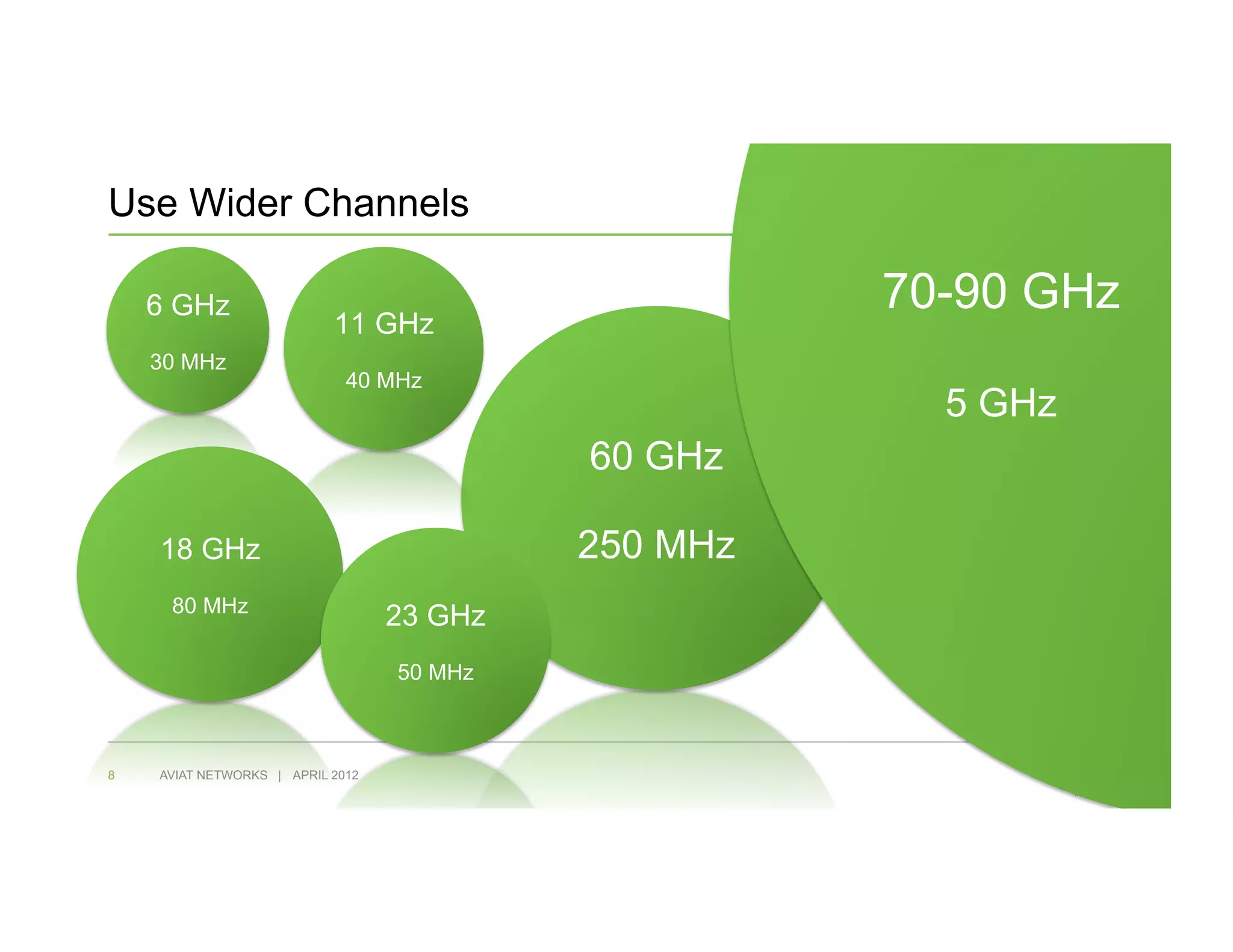

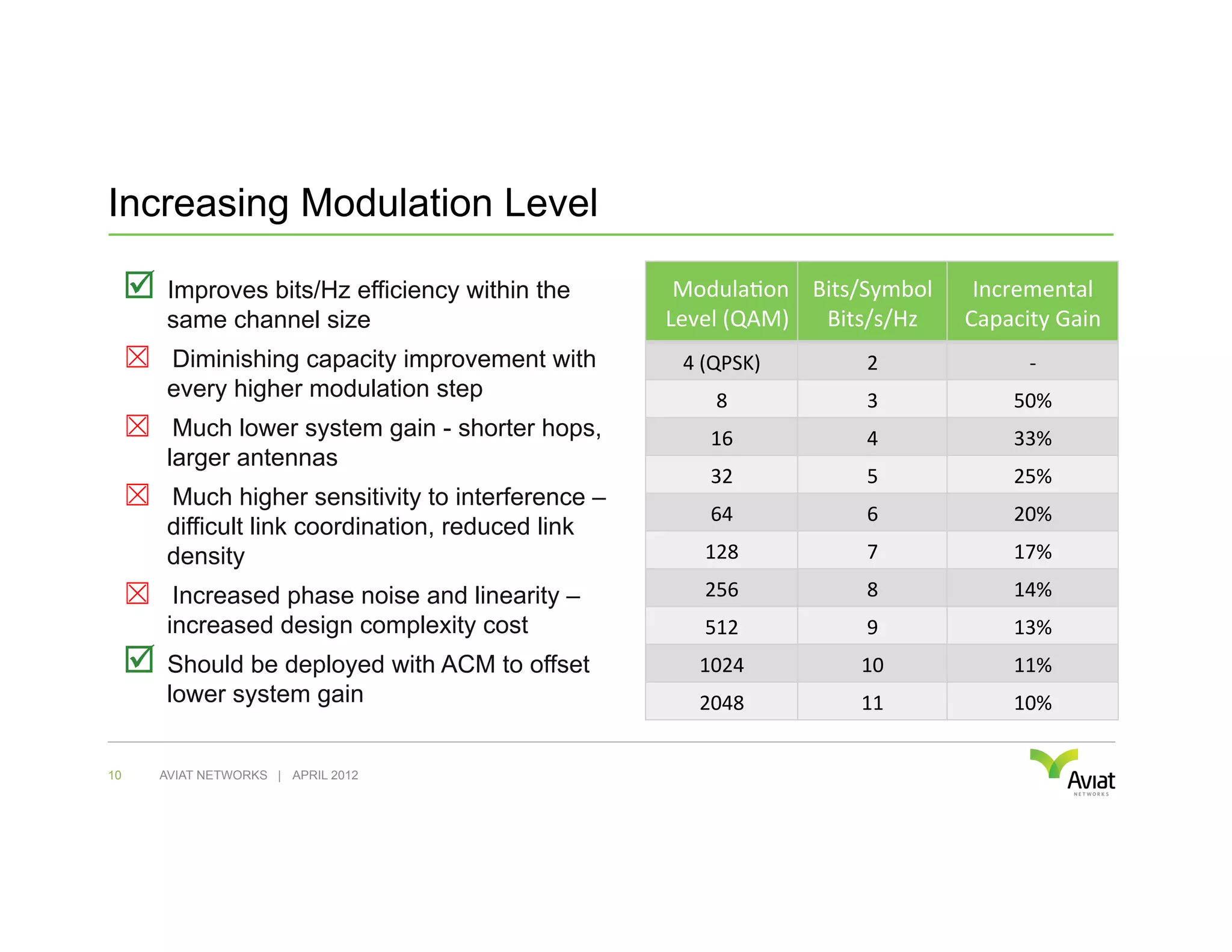
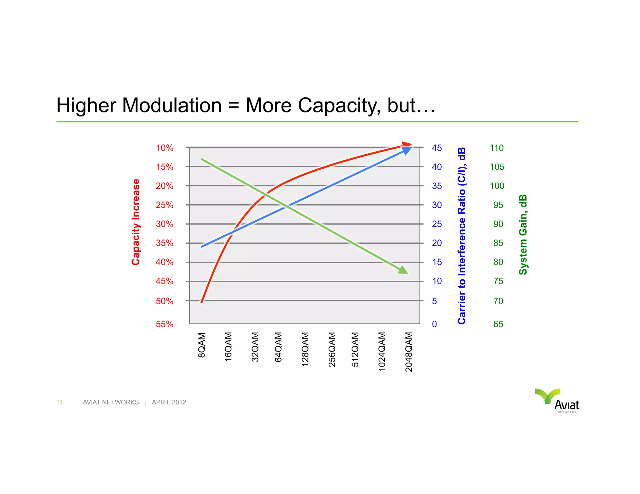
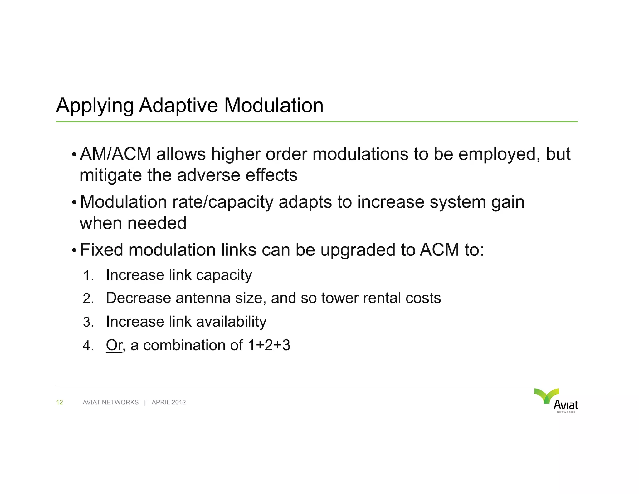

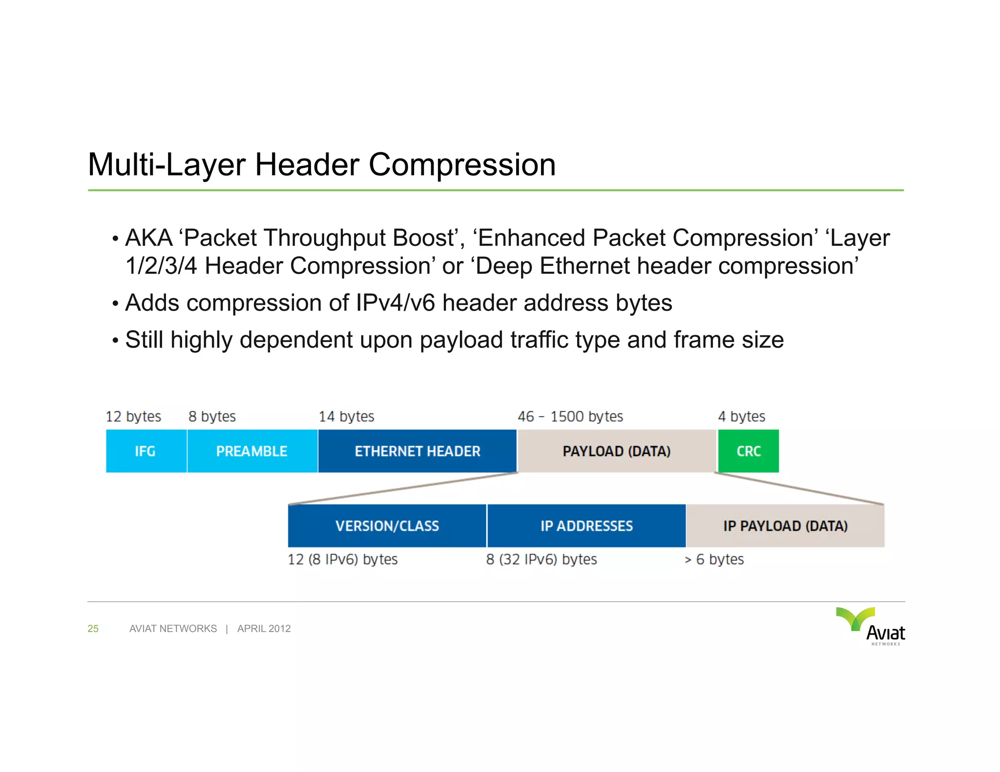
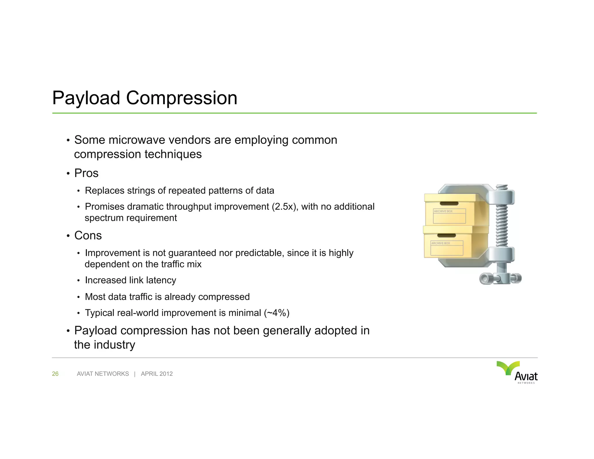
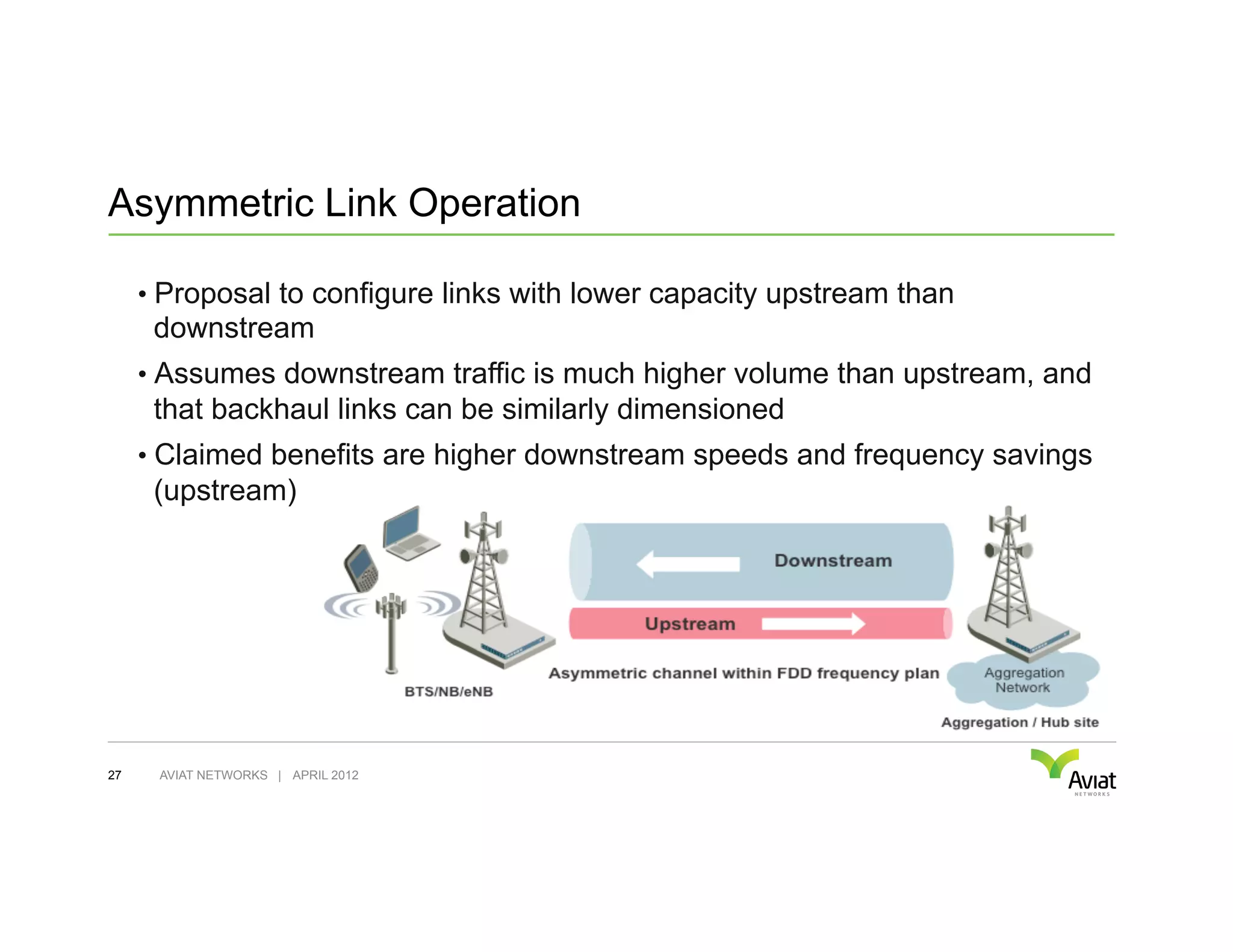

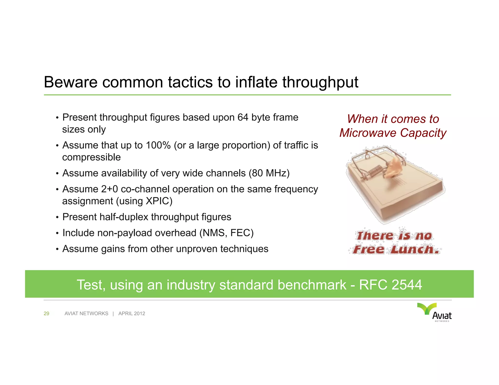
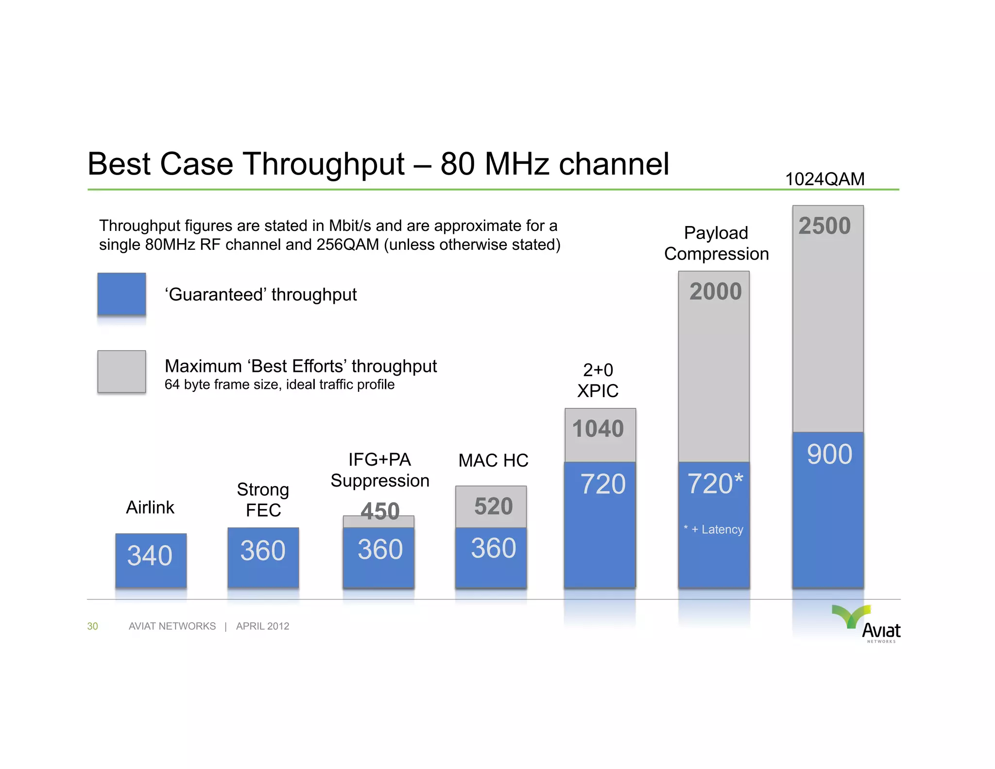
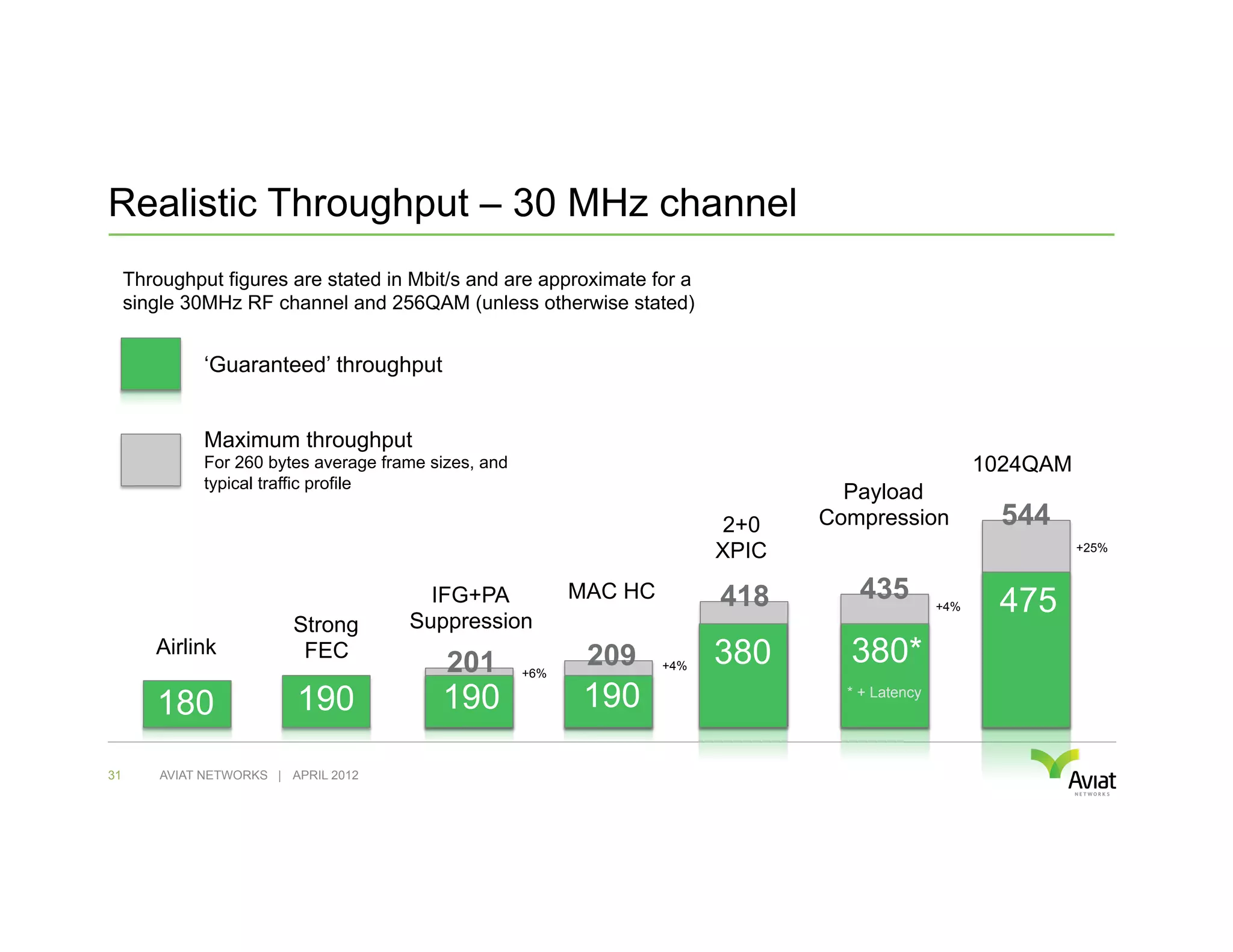
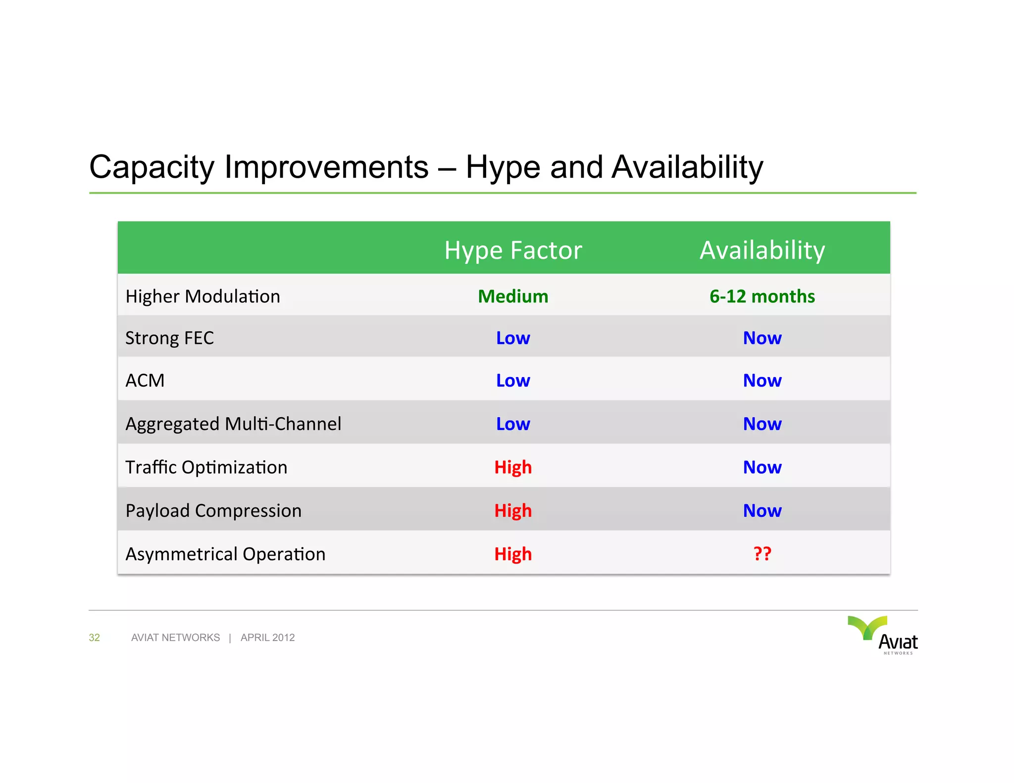


The document discusses various techniques to improve microwave capacity and throughput, including higher modulation levels, wider channels, adaptive modulation, and link aggregation methods. It highlights the importance of understanding vendor claims and the need to be cautious of inflated throughput figures. Strategies such as Ethernet optimization, forward error correction, and asymmetric link operation are also explored to enhance data transmission efficiency.


![Vibe Coding vs. Spec-Driven Development [Free Meetup]](https://cdn.slidesharecdn.com/ss_thumbnails/vibecodingvsspecdrivendevelopment-251209105622-43f455e7-thumbnail.jpg?width=640&height=640&fit=bounds)


