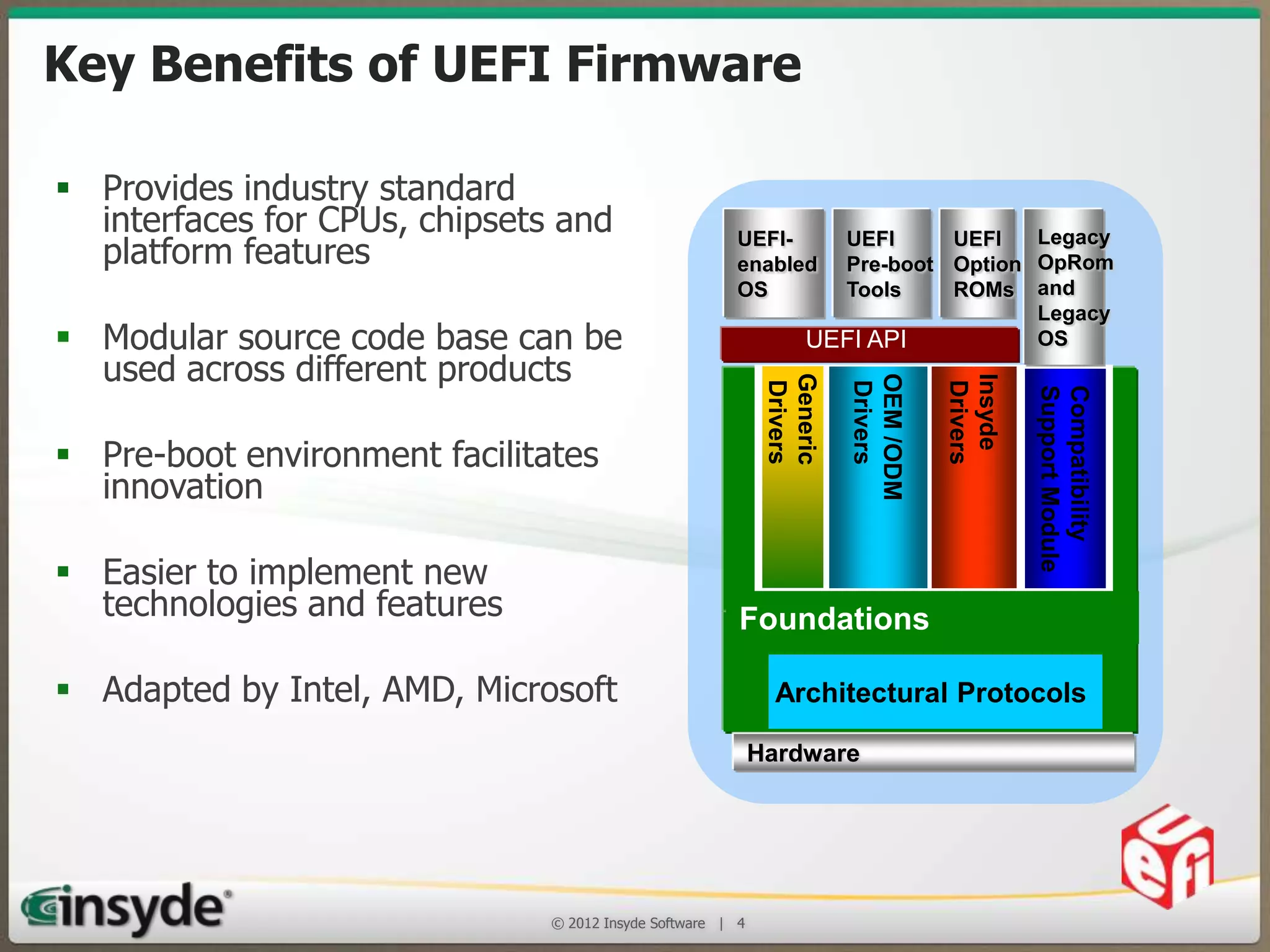
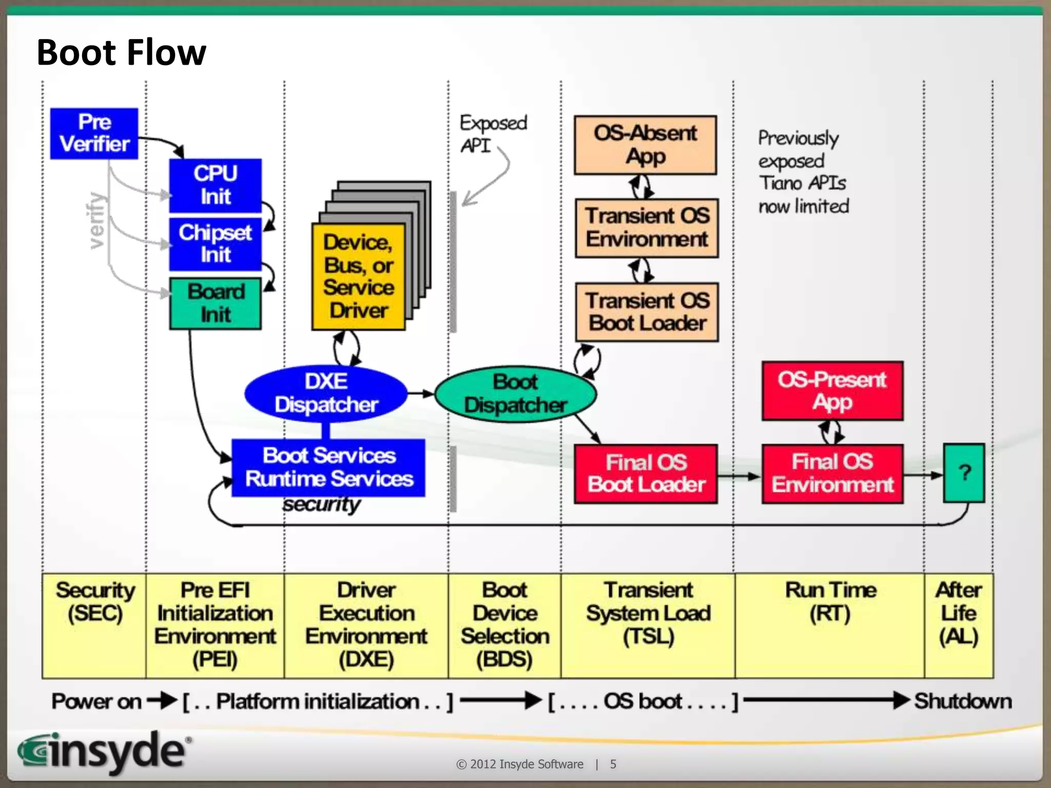
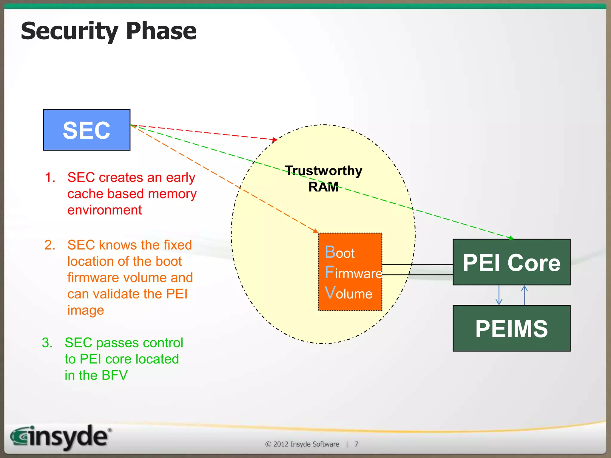
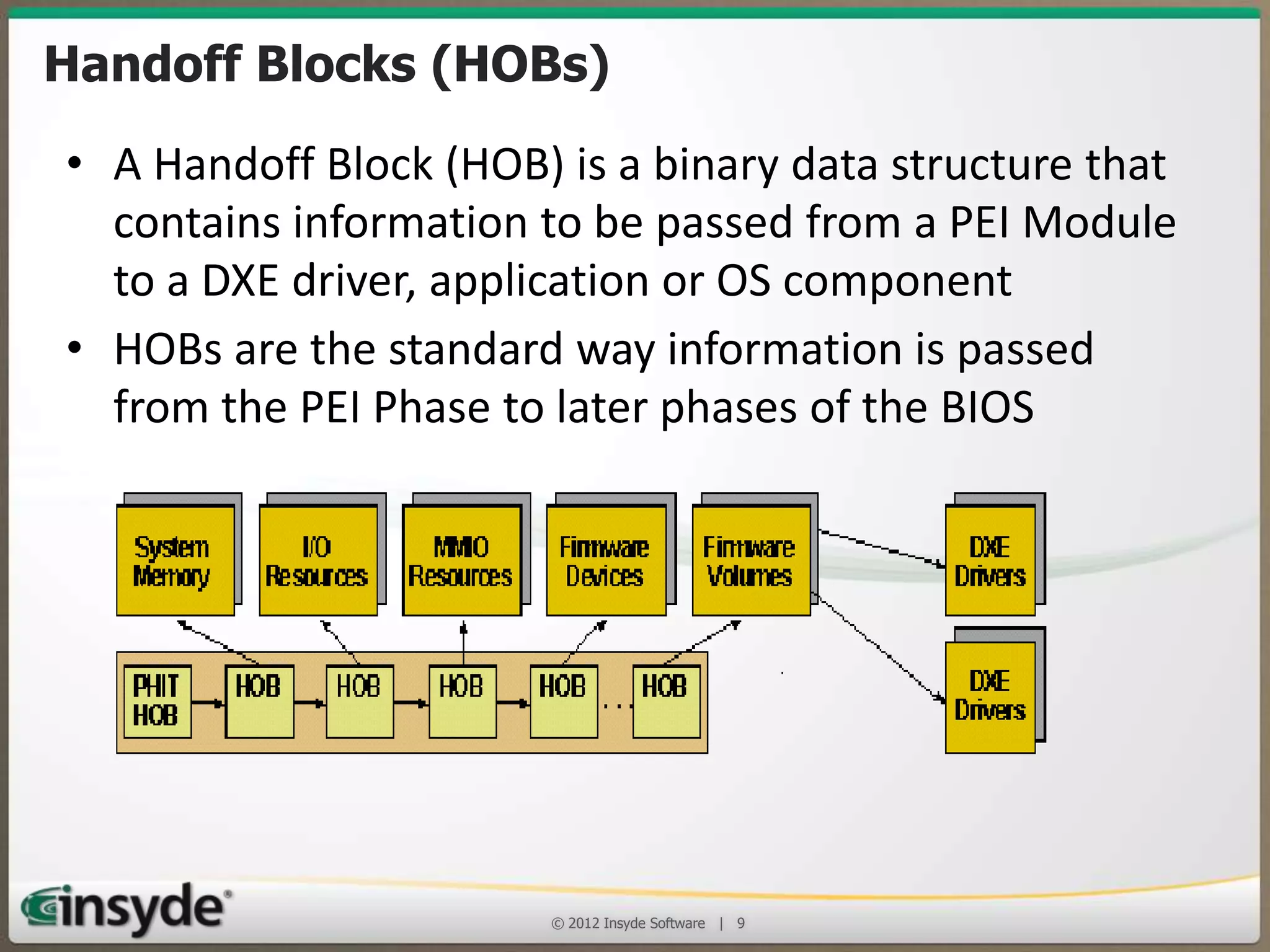
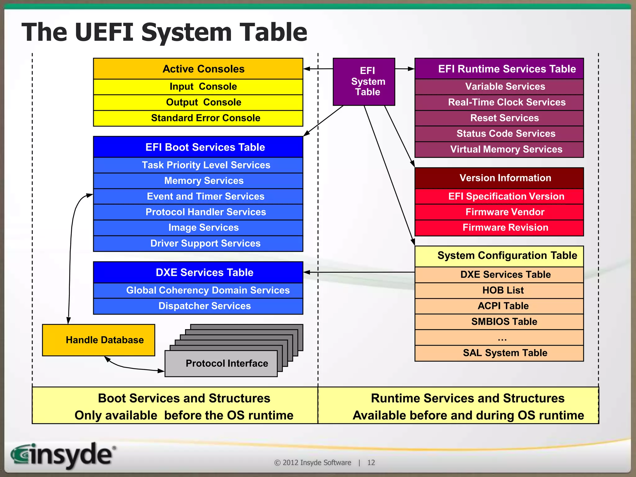
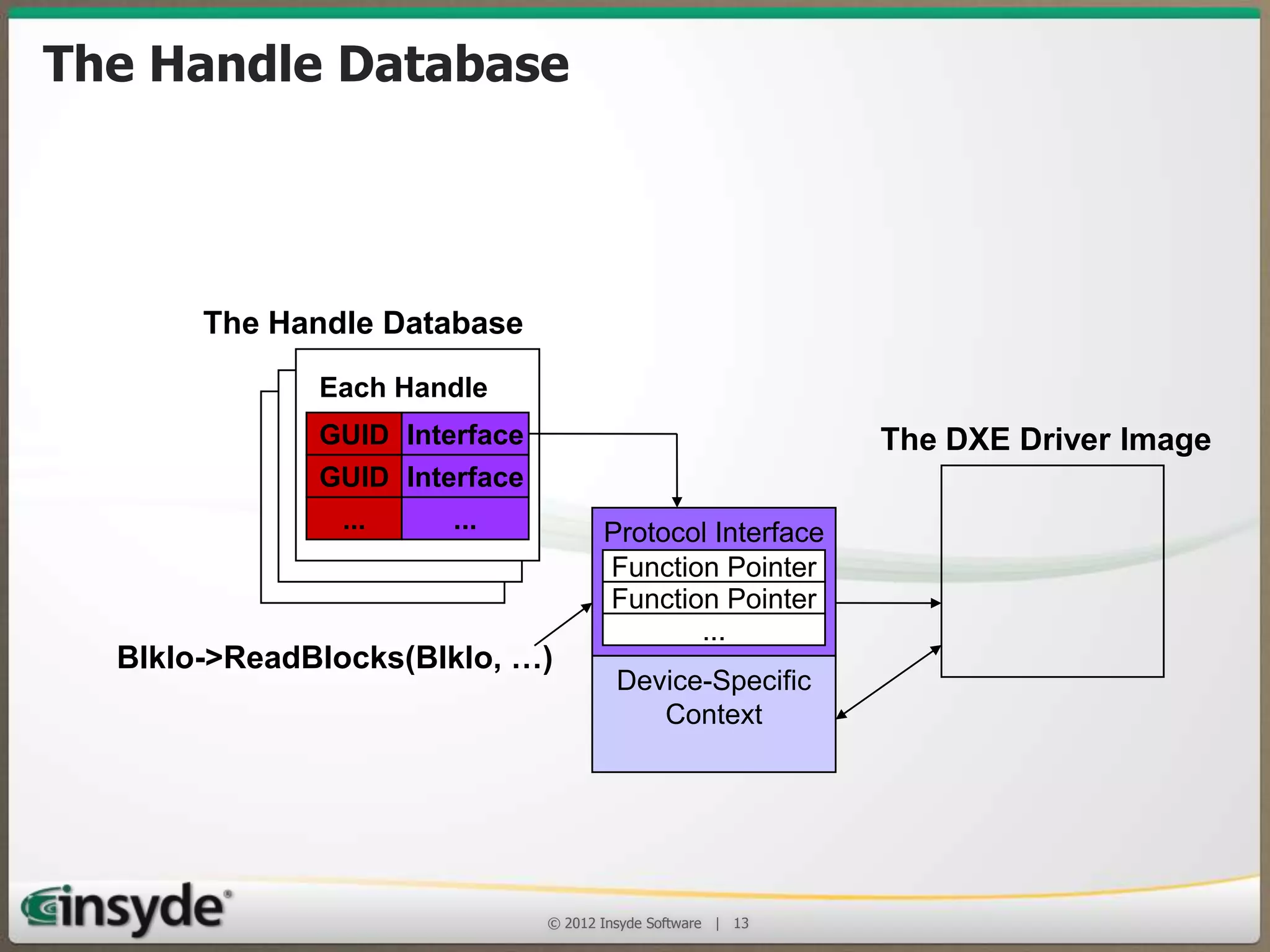
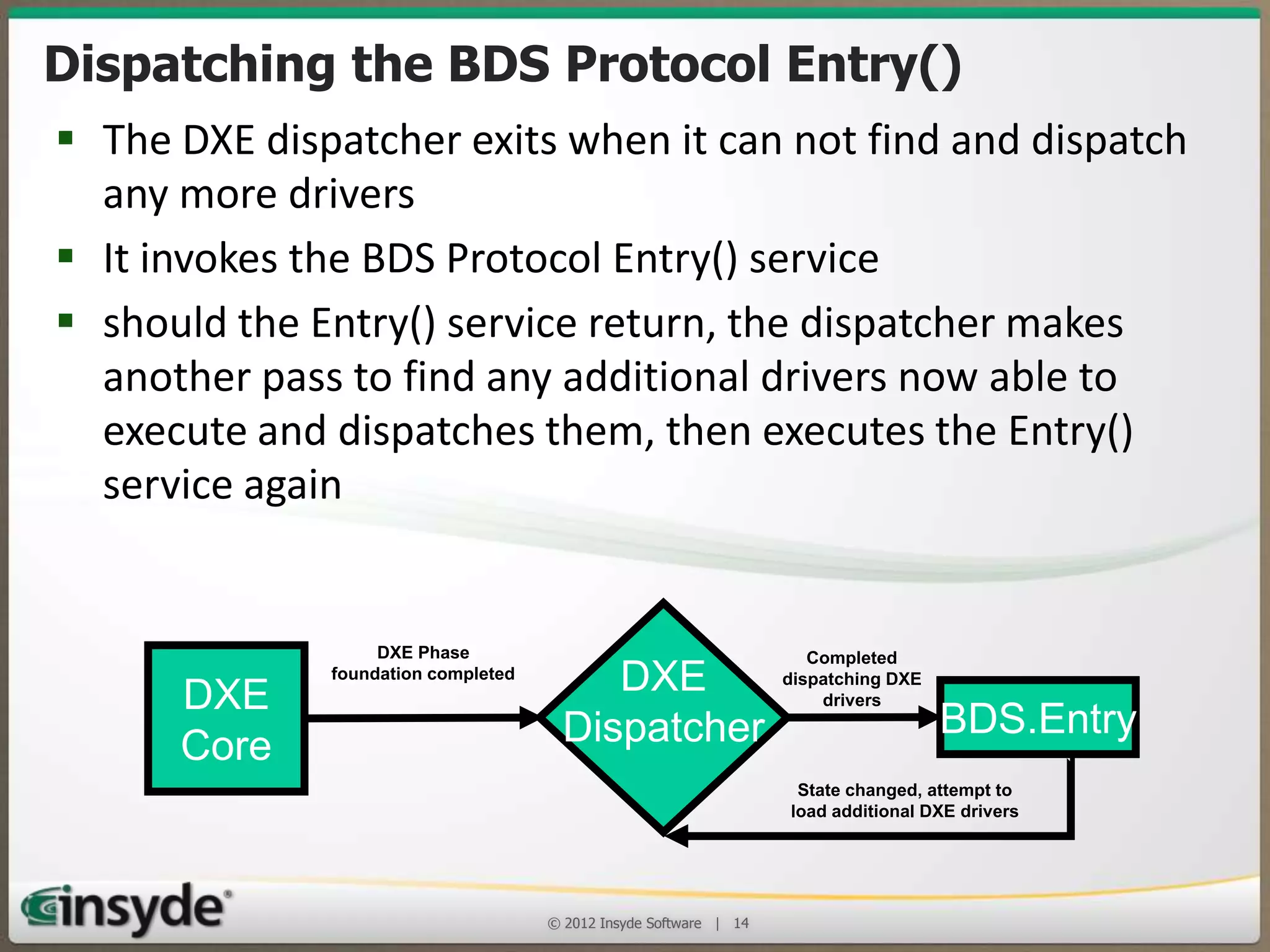
Implementing a UEFI BIOS
in an Embedded System
Insyde Software

© 2013 Insyde Software

1
Insyde Software
• Develops, deploys and supports the latest BIOS
replacement firmware that is based on the UEFI
Framework and UEFI 2.x
• Embedded BIOS business
– Many of Intel’s largest embedded customers continue adoption of
InsydeH2O across multiple business units

• Strong alignment to Intel ECG Roadmap and platforms
• Founded September 1998

© 2013 Insyde Software

2
Agenda
• Understanding the UEFI architecture
• The role of a UEFI BIOS in an x86 embedded
design
• Where to get support when you need it

© 2013 Insyde Software

3
Key Benefits of UEFI Firmware
 Provides industry standard interfaces
for CPUs, chipsets and platform features
 Modular source code base can be used
across different products

Compatibility
Support Module

Insyde
Drivers

 Adapted by Intel, AMD, Microsoft

OEM /ODM
Drivers

 Easier to implement new technologies
and features

Generic
Drivers

 Pre-boot environment facilitates innovation

Legacy
UEFI
UEFI
Pre-boot Option OpRom
Tools
ROMs and
Legacy
OS
UEFI API

UEFIenabled
OS

Foundations
Architectural Protocols
Hardware

© 2013 Insyde Software

4
Boot Flow

© 2013 Insyde Software

5
Security Phase (SEC)
• When the processor’s RESET line is released and the first
instruction is fetched from the RESET vector, the SEC
phase begins
• Objectives:
– The first part of the SEC is a small assembly language
module that switches the processor from 16-bit real
mode to 32-bit protected mode
– Next, it enables a memory model that permits stack
based C code to be executed with only a few
limitations
– The SEC is the security kernel, it can also authenticate the
next phase’s code verifying it to be trustworthy
© 2013 Insyde Software

6
Security Phase
SEC
1. SEC creates an early
cache based memory
environment
2. SEC knows the fixed
location of the boot
firmware volume and
can validate the PEI
image
3. SEC passes control
to PEI core located
in the BFV

Trustworthy
RAM

Boot
Firmware
Volume

PEI Core
PEIMS

© 2013 Insyde Software

7
Pre-EFI Initialization (PEI)
• The PEI phase is responsible for initializing enough of the
system to provide a stable base for the remainder of the BIOS
• PEI phase handles detecting and recovering from corruption
and failure of the firmware store
• PEI phase consists of three stages:
– The smallest possible set of modules to prepare for the
initialization of the memory (critical bus and processor
configuration)
– Memory initialization & capture of information to be passed to
the OS and the remainder of the BIOS
– Checking for firmware corruption and setting the boot mode to
address special cases if necessary
© 2013 Insyde Software

8
Handoff Blocks (HOBs)
• A Handoff Block (HOB) is a binary data structure that
contains information to be passed from a PEI Module
to a DXE driver, application or OS component
• HOBs are the standard way information is passed
from the PEI Phase to later phases of the BIOS

© 2013 Insyde Software

9
The Driver Execution (DXE) Phase
• The DXE phase is that part of the code where most of
the system initialization is performed
– It is loaded and executed once the PEI phase has
finished initializing system memory for the platform.
• Its function is to:
– Do all the remaining necessary hardware setup and set up
the UEFI System Table structures to provide the necessary
services to the Boot Device Selection (BDS) code for it to
run transient applications and OS loaders
– Provide the API interfaces needed by OS loaders to boot
all the supported OSes
© 2013 Insyde Software

10
Components of the DXE Phase
• DXE Core

– Main DXE executable binary; creates tables identifying Boot and Runtime
Services; responsible for dispatching drivers and setting up the DXE tables

• DXE Drivers

– A module loaded by the Core to perform initialization and/or to produce
protocols and other services

• DXE Dispatcher

– Part of the DXE Core: searches for and executes drivers

• DXE Architecture Protocols

– Produced by DXE drivers; to abstract DXE from hardware

• EFI System Table

– Contains pointers to UEFI service tables, configuration
data, thehandle database and console devices
© 2013 Insyde Software

11
The UEFI System Table
Active Consoles
Input Console
Output Console
Standard Error Console

EFI
System
Table

EFI Runtime Services Table
Variable Services
Real-Time Clock Services
Reset Services
Status Code Services

EFI Boot Services Table

Virtual Memory Services

Task Priority Level Services
Memory Services

Version Information

Event and Timer Services

EFI Specification Version

Protocol Handler Services

Firmware Vendor

Image Services

Firmware Revision

Driver Support Services

DXE Services Table
Global Coherency Domain Services
Dispatcher Services

System Configuration Table
DXE Services Table
HOB List
ACPI Table
SMBIOS Table

Handle Database

Protocol Interface
Protocol Interface
Protocol Interface
Protocol Interface
Protocol Interface
Protocol Interface

Boot Services and Structures
Only available before the OS runtime

…
SAL System Table

Runtime Services and Structures
Available before and during OS runtime

© 2013 Insyde Software

12
The Handle Database
The Handle Database
Each Handle
GUID Interface

The DXE Driver Image

GUID Interface
...

...

BlkIo->ReadBlocks(BlkIo, …)

Protocol Interface
Function Pointer
Function Pointer
...
Device-Specific
Context

© 2013 Insyde Software

13
Dispatching the BDS Protocol Entry()
• The DXE dispatcher exits when it can not find and
dispatch any more drivers
• It invokes the BDS Protocol Entry() service
• should the Entry() service return, the dispatcher makes
another pass to find any additional drivers now able to
execute and dispatches them, then executes the Entry()
service again
DXE
Core

DXE Phase foundation
completed

DXE
Dispatcher

Completed
dispatching DXE
drivers

BDS.Entry

State changed, attempt to
load additional DXE drivers

© 2013 Insyde Software

14
Agenda
•

Understanding the UEFI architecture

•

The role of a UEFI BIOS in an x86
embedded design

•

Where to get support when you need it

© 2013 Insyde Software

15
UEFI Advantages
• Embedded system often have unique hardware and a
UEFI BIOS isolates pre-boot applications and OS
initialization code from the hardware
• The code is based on effective standards and UEFI BIOS
uses widely available development environments to
reduce training and learning curve demands
• Since UEFI drivers are written in C and a UEFI BIOS has a
consistent driver architecture and simple dispatchers, a
driver writer can be productive almost immediately
• Using portable coding methods, InsydeH2O is also an
example of how common UEFI BIOS code can support
32- and 64-bit x86, ARM and Itanium platforms
© 2013 Insyde Software

16
Starting a new Huron River based Project
PROJECT_FAMILY
PROJECT_NAME

= ProjectInsyde
= $(DEMOBOARD_NAME)

PROJECT_FAMILY
PROJECT_NAME

= ProjectSeussCorp
= Thing1

2. Edit BuildPlatform.env to point to the
new directory
3. Build a clone of the Huron River CRB
BIOS to check your work

1. Copy the ProjectInsydeHuronRiver
directory to ProjectSeussCorpThing1
© 2013 Insyde Software

17
Adapt the Project Directory to your
Hardware
•
•
•
•
•

•
•

•
•

Change clock generator code if necessary
Change interrupt routing if necessary
Change Smbus MUX code or remove it, as needed
Change SPD addresses if needed
Change Insyde feature set choices to match your
requirements (if you are starting from an Insyde BIOS)
Do a test build: if it is successful, you may have an easy
porting effort
Comment out everything that should not be required for
a first “bring up” build
Build your “bring up” BIOS and test it on the new
hardware
Add commented out features, one at a time
© 2013 Insyde Software

18
Add New Drivers and Feature Support Code
• Here you have to write new code; or you may need
to port code from a previous PPC, ARM or legacy
BIOS
• Some of the new code will be inserted into existing
drivers and PEIMs, some of it will form entirely new
drivers and PEIMs
• These changes often involve the user interface, and
they should be carefully specified so as to minimize
the need to redesign after building the first
prototype

© 2013 Insyde Software

19
Agenda
•

Understanding the UEFI architecture

•

The role of a UEFI BIOS in an x86 embedded
design

•

Where to get support when you need it

© 2013 Insyde Software

20
Don’t Forget Support!
• Insyde Support
•
•
•
•
•
•
•

Engineer to engineer support
Experienced firmware engineers
Worldwide training and certification
Turn key support or support as needed
Worldwide support
Strong Intel partnership
Ready to help – Now!

© 2013 Insyde Software

21
Thank You!

© 2013 Insyde Software

22
Insyde Software is an Affiliate member of the Intel® Intelligent Systems Alliance, a
global ecosystem of 200+ member companies that provide the performance,
connectivity, manageability, and security developers need to create smart, connected
systems

Insyde and InsydeH2O are registered trademarks of Insyde Software.
Intel is a registered trademark of Intel Corporation in the United States and other countries.

© 2013 Insyde Software

23

Implementing a UEFI BIOS into an Embedded System

  • 1.
    Implementing a UEFIBIOS in an Embedded System Insyde Software © 2013 Insyde Software 1
  • 2.
    Insyde Software • Develops,deploys and supports the latest BIOS replacement firmware that is based on the UEFI Framework and UEFI 2.x • Embedded BIOS business – Many of Intel’s largest embedded customers continue adoption of InsydeH2O across multiple business units • Strong alignment to Intel ECG Roadmap and platforms • Founded September 1998 © 2013 Insyde Software 2
  • 3.
    Agenda • Understanding theUEFI architecture • The role of a UEFI BIOS in an x86 embedded design • Where to get support when you need it © 2013 Insyde Software 3
  • 4.
    Key Benefits ofUEFI Firmware  Provides industry standard interfaces for CPUs, chipsets and platform features  Modular source code base can be used across different products Compatibility Support Module Insyde Drivers  Adapted by Intel, AMD, Microsoft OEM /ODM Drivers  Easier to implement new technologies and features Generic Drivers  Pre-boot environment facilitates innovation Legacy UEFI UEFI Pre-boot Option OpRom Tools ROMs and Legacy OS UEFI API UEFIenabled OS Foundations Architectural Protocols Hardware © 2013 Insyde Software 4
  • 5.
    Boot Flow © 2013Insyde Software 5
  • 6.
    Security Phase (SEC) •When the processor’s RESET line is released and the first instruction is fetched from the RESET vector, the SEC phase begins • Objectives: – The first part of the SEC is a small assembly language module that switches the processor from 16-bit real mode to 32-bit protected mode – Next, it enables a memory model that permits stack based C code to be executed with only a few limitations – The SEC is the security kernel, it can also authenticate the next phase’s code verifying it to be trustworthy © 2013 Insyde Software 6
  • 7.
    Security Phase SEC 1. SECcreates an early cache based memory environment 2. SEC knows the fixed location of the boot firmware volume and can validate the PEI image 3. SEC passes control to PEI core located in the BFV Trustworthy RAM Boot Firmware Volume PEI Core PEIMS © 2013 Insyde Software 7
  • 8.
    Pre-EFI Initialization (PEI) •The PEI phase is responsible for initializing enough of the system to provide a stable base for the remainder of the BIOS • PEI phase handles detecting and recovering from corruption and failure of the firmware store • PEI phase consists of three stages: – The smallest possible set of modules to prepare for the initialization of the memory (critical bus and processor configuration) – Memory initialization & capture of information to be passed to the OS and the remainder of the BIOS – Checking for firmware corruption and setting the boot mode to address special cases if necessary © 2013 Insyde Software 8
  • 9.
    Handoff Blocks (HOBs) •A Handoff Block (HOB) is a binary data structure that contains information to be passed from a PEI Module to a DXE driver, application or OS component • HOBs are the standard way information is passed from the PEI Phase to later phases of the BIOS © 2013 Insyde Software 9
  • 10.
    The Driver Execution(DXE) Phase • The DXE phase is that part of the code where most of the system initialization is performed – It is loaded and executed once the PEI phase has finished initializing system memory for the platform. • Its function is to: – Do all the remaining necessary hardware setup and set up the UEFI System Table structures to provide the necessary services to the Boot Device Selection (BDS) code for it to run transient applications and OS loaders – Provide the API interfaces needed by OS loaders to boot all the supported OSes © 2013 Insyde Software 10
  • 11.
    Components of theDXE Phase • DXE Core – Main DXE executable binary; creates tables identifying Boot and Runtime Services; responsible for dispatching drivers and setting up the DXE tables • DXE Drivers – A module loaded by the Core to perform initialization and/or to produce protocols and other services • DXE Dispatcher – Part of the DXE Core: searches for and executes drivers • DXE Architecture Protocols – Produced by DXE drivers; to abstract DXE from hardware • EFI System Table – Contains pointers to UEFI service tables, configuration data, thehandle database and console devices © 2013 Insyde Software 11
  • 12.
    The UEFI SystemTable Active Consoles Input Console Output Console Standard Error Console EFI System Table EFI Runtime Services Table Variable Services Real-Time Clock Services Reset Services Status Code Services EFI Boot Services Table Virtual Memory Services Task Priority Level Services Memory Services Version Information Event and Timer Services EFI Specification Version Protocol Handler Services Firmware Vendor Image Services Firmware Revision Driver Support Services DXE Services Table Global Coherency Domain Services Dispatcher Services System Configuration Table DXE Services Table HOB List ACPI Table SMBIOS Table Handle Database Protocol Interface Protocol Interface Protocol Interface Protocol Interface Protocol Interface Protocol Interface Boot Services and Structures Only available before the OS runtime … SAL System Table Runtime Services and Structures Available before and during OS runtime © 2013 Insyde Software 12
  • 13.
    The Handle Database TheHandle Database Each Handle GUID Interface The DXE Driver Image GUID Interface ... ... BlkIo->ReadBlocks(BlkIo, …) Protocol Interface Function Pointer Function Pointer ... Device-Specific Context © 2013 Insyde Software 13
  • 14.
    Dispatching the BDSProtocol Entry() • The DXE dispatcher exits when it can not find and dispatch any more drivers • It invokes the BDS Protocol Entry() service • should the Entry() service return, the dispatcher makes another pass to find any additional drivers now able to execute and dispatches them, then executes the Entry() service again DXE Core DXE Phase foundation completed DXE Dispatcher Completed dispatching DXE drivers BDS.Entry State changed, attempt to load additional DXE drivers © 2013 Insyde Software 14
  • 15.
    Agenda • Understanding the UEFIarchitecture • The role of a UEFI BIOS in an x86 embedded design • Where to get support when you need it © 2013 Insyde Software 15
  • 16.
    UEFI Advantages • Embeddedsystem often have unique hardware and a UEFI BIOS isolates pre-boot applications and OS initialization code from the hardware • The code is based on effective standards and UEFI BIOS uses widely available development environments to reduce training and learning curve demands • Since UEFI drivers are written in C and a UEFI BIOS has a consistent driver architecture and simple dispatchers, a driver writer can be productive almost immediately • Using portable coding methods, InsydeH2O is also an example of how common UEFI BIOS code can support 32- and 64-bit x86, ARM and Itanium platforms © 2013 Insyde Software 16
  • 17.
    Starting a newHuron River based Project PROJECT_FAMILY PROJECT_NAME = ProjectInsyde = $(DEMOBOARD_NAME) PROJECT_FAMILY PROJECT_NAME = ProjectSeussCorp = Thing1 2. Edit BuildPlatform.env to point to the new directory 3. Build a clone of the Huron River CRB BIOS to check your work 1. Copy the ProjectInsydeHuronRiver directory to ProjectSeussCorpThing1 © 2013 Insyde Software 17
  • 18.
    Adapt the ProjectDirectory to your Hardware • • • • • • • • • Change clock generator code if necessary Change interrupt routing if necessary Change Smbus MUX code or remove it, as needed Change SPD addresses if needed Change Insyde feature set choices to match your requirements (if you are starting from an Insyde BIOS) Do a test build: if it is successful, you may have an easy porting effort Comment out everything that should not be required for a first “bring up” build Build your “bring up” BIOS and test it on the new hardware Add commented out features, one at a time © 2013 Insyde Software 18
  • 19.
    Add New Driversand Feature Support Code • Here you have to write new code; or you may need to port code from a previous PPC, ARM or legacy BIOS • Some of the new code will be inserted into existing drivers and PEIMs, some of it will form entirely new drivers and PEIMs • These changes often involve the user interface, and they should be carefully specified so as to minimize the need to redesign after building the first prototype © 2013 Insyde Software 19
  • 20.
    Agenda • Understanding the UEFIarchitecture • The role of a UEFI BIOS in an x86 embedded design • Where to get support when you need it © 2013 Insyde Software 20
  • 21.
    Don’t Forget Support! •Insyde Support • • • • • • • Engineer to engineer support Experienced firmware engineers Worldwide training and certification Turn key support or support as needed Worldwide support Strong Intel partnership Ready to help – Now! © 2013 Insyde Software 21
  • 22.
    Thank You! © 2013Insyde Software 22
  • 23.
    Insyde Software isan Affiliate member of the Intel® Intelligent Systems Alliance, a global ecosystem of 200+ member companies that provide the performance, connectivity, manageability, and security developers need to create smart, connected systems Insyde and InsydeH2O are registered trademarks of Insyde Software. Intel is a registered trademark of Intel Corporation in the United States and other countries. © 2013 Insyde Software 23