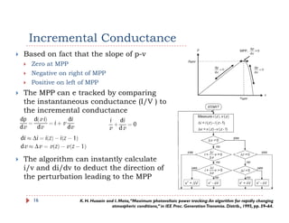
Maximum Power Point Tracking inMaximum Power Point Tracking in
Solar PV Systems
CEP Course on “ConverterTopologies for Grid Connected PV System”
Prof Suryanarayana DoollaProf. Suryanarayana Doolla
Dept. of Energy Science and Engineering
Indian Institute of Technology Bombay
OutlineOutline
Need of MPPT and its History
Various Techniques
Analysis
SSummary
2
Need of MPPTNeed of MPPT
PV power is increasingly connected to grid
Large ScaleLarge Scale
Small Scale
Efficiency of Solar PV Cells
Earliest MPPT methods published in 1960s
Several methods are proposed in literature
Direct method
Indirect method
Short Circuitt Open CircuitShort Circuitt, Open Circuit
Prior evaluation of panel, based on mathematical
relationships, Database not valid for all operating and
meteorological conditions
3
Maximum Power Point TrackingMaximum Power Point Tracking
To automatically find the voltage (VMPP) or
current (IMPP) at which a PV array shouldcurrent (IMPP) at which a PV array should
operate to obtain the maximum power output
(PMPP)under a given temperature and irradiance.
Partial shading conditions
It is possible to have multiple local maxima, but
overall there is still only one true MPP.
4
TopologyTopology
Load
dc/dc
converter
Storage
Next Stage
Inverter Grid
5
MPPT
Choice of MPPT TechniqueChoice of MPPT Technique
Implementation complexity
Sensors requiredSensors required
Ability to detect multiple local maxima
CostCost
Application
Response timeResponse time
6
I-V CurveI V Curve
I-V Characteristics at four different
radiation levels
I-V Characteristics for three different
temperature levels
7
P-V CurveP V Curve
P-V Characteristics at four different
radiation levels
P-V Characteristics for three different
temperature levels
8
Indirect Methods (quasi seeks)Indirect Methods (quasi seeks)
MPP is estimated from
Voltage
Current
The irradiance
Using empirical dataUs g e p c d t
Mathematical expressions of numerical approx.
The estimation is carried out for a specific PV
generator installed in the systemgenerator installed in the system
Some Techniques
Curve fitting method
Lookup table method
Fractional OC method
Fractional SC method
9
Direct Methods (true seeking)Direct Methods (true seeking)
Use voltage and/or current information
Prior knowledge of PV panel is not requiredPrior knowledge of PV panel is not required
Independent of isolation, temperature and
degradation levelsg
Computational intensive
Some Techniquesq
Hill climbing/P&O
Incremental Conductance
Fuzzy Logic Control
Slide Control Method
10
Fractional Open-Circuit VoltageFractional Open Circuit Voltage
Near linear relationship between VOC and VMPP
k1 is a constant of proportionality (0.71-0.78)and
depends on
h t i ti f th PV b i dcharacteristics of the PV array being used
computed beforehand emperically
VMPP and VOC for specific PV array at different irradiance and
temperaturep
Once k1 is known, VOC is measured by shutting down
the converter, periodically.
Power loss associated with shutting down
Pilot cells can be used parallelly
PV array never operates at MPP (approximation)
Not valid in case of partial shading
11
g
Source: H.-J. Noh, D.-Y. Lee, and D.-S. Hyun,“An improved MPPT converter with current compensation method for
small scaled PV-applications,” in Proc. 28th Annu. Conf. Ind. Electron. Soc., 2002, pp. 1113–1118
Hill Climbing/Perturb & Observe TechniqueHill Climbing/Perturb & Observe Technique
Incrementing the
voltage increases the
power when operating
on the left of the MPP
and decreases the
power when on the right
of the MPP.
Hill climbing involves aHill climbing involves a
perturbation in the
duty ratio
P&O a perturbation inP&O a perturbation in
the operating voltage of
the PV array
12
Flow Chart for P&O AlgorithmFlow Chart for P&O Algorithm
13
Source: I. Houssamo et al. / Electrical Power and Energy Systems 46 (2013) 98–107
Hill Climbing/Perturb & Observe TechniqueHill Climbing/Perturb & Observe Technique
Hill climbing and P&O methods can fail under rapidly changing
atmospheric conditions
If the irradiance increases and shifts the power curve from P toIf the irradiance increases and shifts the power curve from P1 to
P2 within one sampling period, the operating point will move
from A to C.
A three-point weight comparison P&O
Compares the actual power point to two preceding ones before a
decision is made about the perturbation sign
Can be implemented usingCan be implemented using
digital/analog circuitry
Two sensors are required to
implementimplement
14
Hill Climbing/Perturb & Observe TechniqueHill Climbing/Perturb & Observe Technique
The process is repeated periodically until the
MPP is reached.MPP is reached.
The system then oscillates about the MPP.
The oscillation can be minimized by reducing they g
perturbation step size.
Smaller perturbation size slows down the MPPT.
Variable perturbation size that gets smaller towardsVariable perturbation size that gets smaller towards
the MPP
Fuzzy logic control is used to optimize the magnitude of
the next perturbation.
15
Incremental ConductanceIncremental Conductance
Based on fact that the slope of p-v
Zero at MPP
Negative on right of MPP
Positive on left of MPP
The MPP can e tracked by comparing
the instantaneous conductance (I/V ) to
the incremental conductance
The algorithm can instantly calculate
i/v and di/dv to deduct the direction of
the perturbation leading to the MPP
16 K. H. Hussein and I. Mota,“Maximum photovoltaic power tracking:An algorithm for rapidly changing
atmospheric conditions,” in IEE Proc. GenerationTransmiss. Distrib., 1995, pp. 59–64.
Comparison- P&O and INC MethodsComparison P&O and INC Methods
Concerning power efficiency, theoretically, INC method could
provide a better tracking of MPP than P&O algorithm
Due to the noise and error measurements it is difficult to
satisfy some of the equations
It produces oscillations around the MPP and power loss
Complex to implement when compared to P&O
Tracking step value has a significant effect on effectiveness of
MPPTMPPT
When tracking step value is chosen correctly, P&O can have
an energy efficiency equivalent to that obtained with INC
Modified to obtain MPP even in partial shading conditionsModified to obtain MPP even in partial shading conditions
17
Major Characteristics - ComparisonMajor Characteristics Comparison
Technique Array
depe
ndent
True
MPPT?
Analog
or Digital
Periodic
Tuning
Convergenc
e Speed
Implementation
Complexity
Sensed
parameters
ndent
P&O NO YES Both NO Varies Low V, I
INC NO YES Digital NO Varies Medium V, I
FracVOC YES NO Both Yes Medium Low V
Frac ISC YES NO Both Yes Medium Medium I
RCC NO YES Analog NO Fast Low V, I
dp/dv or
dp/di
NO YES Digital NO Fast Medium V, I
Impp and
Vmpp
YES YES Digital Yes N/A Medium Irradiance,
temperatureVmpp temperature
OCC Yes No Both Yes Fast Medium Current
Current
Sweep
Yes Yes Digital Yes Slow High V, I
18 Source:T. Esram, and P. L. Chapman,“Comparison of Photovoltaic Array Maximum Power PointTrackingTechniques,” IEEE
transactions on energy conversion, vol. 22, no. 2, june 2007.
ApplicationsApplications
Space and Orbital Stations
Cost and complexity are not an issue,p y ,
High Reliability and performance
Hill climbing/P&O, IncCond, and RCC are appropriate
S l hi lSolar Vehicles
Require fast convergence to MPP
Fuzzy logic control, neural network, RCC, load current orFuzzy logic control, neural network, RCC, load current or
load voltage maximization may be considered
Residential Use
P i l h di i b k iPartial shading issues, payback time
Two stage incremental conductance, current sweep
methods, OCC MPPT
19
ApplicationsApplications
Street lighting
Charging of batteries during the dayCharging of batteries during the day
Easy and cheap implementation is more important
Fractional VOC and/or Fractional ISC
20
Thank you!!
Prof. Suryanarayana Doolla
Email: suryad@iitb ac inEmail: suryad@iitb.ac.in
21

Iitbombay report

  • 1.
    Maximum Power PointTracking inMaximum Power Point Tracking in Solar PV Systems CEP Course on “ConverterTopologies for Grid Connected PV System” Prof Suryanarayana DoollaProf. Suryanarayana Doolla Dept. of Energy Science and Engineering Indian Institute of Technology Bombay
  • 2.
    OutlineOutline Need of MPPTand its History Various Techniques Analysis SSummary 2
  • 3.
    Need of MPPTNeedof MPPT PV power is increasingly connected to grid Large ScaleLarge Scale Small Scale Efficiency of Solar PV Cells Earliest MPPT methods published in 1960s Several methods are proposed in literature Direct method Indirect method Short Circuitt Open CircuitShort Circuitt, Open Circuit Prior evaluation of panel, based on mathematical relationships, Database not valid for all operating and meteorological conditions 3
  • 4.
    Maximum Power PointTrackingMaximum Power Point Tracking To automatically find the voltage (VMPP) or current (IMPP) at which a PV array shouldcurrent (IMPP) at which a PV array should operate to obtain the maximum power output (PMPP)under a given temperature and irradiance. Partial shading conditions It is possible to have multiple local maxima, but overall there is still only one true MPP. 4
  • 5.
  • 6.
    Choice of MPPTTechniqueChoice of MPPT Technique Implementation complexity Sensors requiredSensors required Ability to detect multiple local maxima CostCost Application Response timeResponse time 6
  • 7.
    I-V CurveI VCurve I-V Characteristics at four different radiation levels I-V Characteristics for three different temperature levels 7
  • 8.
    P-V CurveP VCurve P-V Characteristics at four different radiation levels P-V Characteristics for three different temperature levels 8
  • 9.
    Indirect Methods (quasiseeks)Indirect Methods (quasi seeks) MPP is estimated from Voltage Current The irradiance Using empirical dataUs g e p c d t Mathematical expressions of numerical approx. The estimation is carried out for a specific PV generator installed in the systemgenerator installed in the system Some Techniques Curve fitting method Lookup table method Fractional OC method Fractional SC method 9
  • 10.
    Direct Methods (trueseeking)Direct Methods (true seeking) Use voltage and/or current information Prior knowledge of PV panel is not requiredPrior knowledge of PV panel is not required Independent of isolation, temperature and degradation levelsg Computational intensive Some Techniquesq Hill climbing/P&O Incremental Conductance Fuzzy Logic Control Slide Control Method 10
  • 11.
    Fractional Open-Circuit VoltageFractionalOpen Circuit Voltage Near linear relationship between VOC and VMPP k1 is a constant of proportionality (0.71-0.78)and depends on h t i ti f th PV b i dcharacteristics of the PV array being used computed beforehand emperically VMPP and VOC for specific PV array at different irradiance and temperaturep Once k1 is known, VOC is measured by shutting down the converter, periodically. Power loss associated with shutting down Pilot cells can be used parallelly PV array never operates at MPP (approximation) Not valid in case of partial shading 11 g Source: H.-J. Noh, D.-Y. Lee, and D.-S. Hyun,“An improved MPPT converter with current compensation method for small scaled PV-applications,” in Proc. 28th Annu. Conf. Ind. Electron. Soc., 2002, pp. 1113–1118
  • 12.
    Hill Climbing/Perturb &Observe TechniqueHill Climbing/Perturb & Observe Technique Incrementing the voltage increases the power when operating on the left of the MPP and decreases the power when on the right of the MPP. Hill climbing involves aHill climbing involves a perturbation in the duty ratio P&O a perturbation inP&O a perturbation in the operating voltage of the PV array 12
  • 13.
    Flow Chart forP&O AlgorithmFlow Chart for P&O Algorithm 13 Source: I. Houssamo et al. / Electrical Power and Energy Systems 46 (2013) 98–107
  • 14.
    Hill Climbing/Perturb &Observe TechniqueHill Climbing/Perturb & Observe Technique Hill climbing and P&O methods can fail under rapidly changing atmospheric conditions If the irradiance increases and shifts the power curve from P toIf the irradiance increases and shifts the power curve from P1 to P2 within one sampling period, the operating point will move from A to C. A three-point weight comparison P&O Compares the actual power point to two preceding ones before a decision is made about the perturbation sign Can be implemented usingCan be implemented using digital/analog circuitry Two sensors are required to implementimplement 14
  • 15.
    Hill Climbing/Perturb &Observe TechniqueHill Climbing/Perturb & Observe Technique The process is repeated periodically until the MPP is reached.MPP is reached. The system then oscillates about the MPP. The oscillation can be minimized by reducing they g perturbation step size. Smaller perturbation size slows down the MPPT. Variable perturbation size that gets smaller towardsVariable perturbation size that gets smaller towards the MPP Fuzzy logic control is used to optimize the magnitude of the next perturbation. 15
  • 16.
    Incremental ConductanceIncremental Conductance Basedon fact that the slope of p-v Zero at MPP Negative on right of MPP Positive on left of MPP The MPP can e tracked by comparing the instantaneous conductance (I/V ) to the incremental conductance The algorithm can instantly calculate i/v and di/dv to deduct the direction of the perturbation leading to the MPP 16 K. H. Hussein and I. Mota,“Maximum photovoltaic power tracking:An algorithm for rapidly changing atmospheric conditions,” in IEE Proc. GenerationTransmiss. Distrib., 1995, pp. 59–64.
  • 17.
    Comparison- P&O andINC MethodsComparison P&O and INC Methods Concerning power efficiency, theoretically, INC method could provide a better tracking of MPP than P&O algorithm Due to the noise and error measurements it is difficult to satisfy some of the equations It produces oscillations around the MPP and power loss Complex to implement when compared to P&O Tracking step value has a significant effect on effectiveness of MPPTMPPT When tracking step value is chosen correctly, P&O can have an energy efficiency equivalent to that obtained with INC Modified to obtain MPP even in partial shading conditionsModified to obtain MPP even in partial shading conditions 17
  • 18.
    Major Characteristics -ComparisonMajor Characteristics Comparison Technique Array depe ndent True MPPT? Analog or Digital Periodic Tuning Convergenc e Speed Implementation Complexity Sensed parameters ndent P&O NO YES Both NO Varies Low V, I INC NO YES Digital NO Varies Medium V, I FracVOC YES NO Both Yes Medium Low V Frac ISC YES NO Both Yes Medium Medium I RCC NO YES Analog NO Fast Low V, I dp/dv or dp/di NO YES Digital NO Fast Medium V, I Impp and Vmpp YES YES Digital Yes N/A Medium Irradiance, temperatureVmpp temperature OCC Yes No Both Yes Fast Medium Current Current Sweep Yes Yes Digital Yes Slow High V, I 18 Source:T. Esram, and P. L. Chapman,“Comparison of Photovoltaic Array Maximum Power PointTrackingTechniques,” IEEE transactions on energy conversion, vol. 22, no. 2, june 2007.
  • 19.
    ApplicationsApplications Space and OrbitalStations Cost and complexity are not an issue,p y , High Reliability and performance Hill climbing/P&O, IncCond, and RCC are appropriate S l hi lSolar Vehicles Require fast convergence to MPP Fuzzy logic control, neural network, RCC, load current orFuzzy logic control, neural network, RCC, load current or load voltage maximization may be considered Residential Use P i l h di i b k iPartial shading issues, payback time Two stage incremental conductance, current sweep methods, OCC MPPT 19
  • 20.
    ApplicationsApplications Street lighting Charging ofbatteries during the dayCharging of batteries during the day Easy and cheap implementation is more important Fractional VOC and/or Fractional ISC 20
  • 21.
    Thank you!! Prof. SuryanarayanaDoolla Email: suryad@iitb ac inEmail: suryad@iitb.ac.in 21