Transcript: New from BookNet Canada for 2024: BNC BiblioShare - Tech Forum 2024
Iai 05 rc general_cj0203-2_a_p371-416_gripper
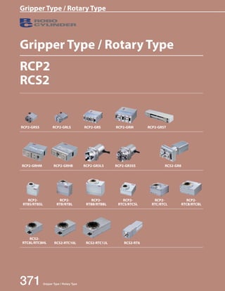
1. Gripper Type / Rotary Type
RCP2 ROBO Cylinder 371 Gripper Type / Rotary Type
RCP2
RCS2
RCP2-GRM RCP2-GRST
RCP2-GRHB RCP2-GR3SS
Gripper Type / Rotary Type
RCP2-GRSS
RCS2-RT6
RCP2-GRHM
RCP2-GRLS
RCS2-RTC10L
RCP2-GRS
RCS2-RTC12L
RCS2-GR8
RCP2-
RTBS/RTBSL
RCS2-
RTC8L/RTC8HL
RCP2-
RTB/RTBL
RCP2-
RTBB/RTBBL
RCP2-
RTCS/RTCSL
RCP2-
RTC/RTCL
RCP2-
RTCB/RTCBL
RCP2-GR3LS
2. RCP2 ROBO Cylinder
Gripper Type / Rotary Type 372
Slider
Type
Mini
Standard
Controllers
Integrated
Rod
Type
Mini
Standard
Controllers
Integrated
Table/
Arm/
Flat Type
Mini
Standard
Gripper/
Rotary
Type
Linear
Servo
Type
Clean-room
Type
Splash-
Proof
Type
Pulse
Motor
Servo
Motor
(24V)
Servo
Motor
(200V)
Linear
Servo
Motor
Gripper Type / Rotary Type
RCP2
series
Pulse
Motor
Type
2-Finger Gripper Mini Slider Type 42mm Width RCP2-GRSS 373
Mini Lever Type 42mm Width RCP2-GRLS 375
Small Slider Type 69mm Width RCP2-GRS 377
Medium Slider Type 74mm Width RCP2-GRM 379
Long Stroke Slider Type 130mm Width RCP2-GRST 381
~ ~
190mm Width
Medium High-force Gripper 116mm Width RCP2-GRHM 383
Large High-force Gripper 131mm Width RCP2-GRHB 385
3-Finger Gripper Lever Type 62mm Width RCP2-GR3LS 387
80mm Width RCP2-GR3LM 389
Slider Type 62mm Width RCP2-GR3SS 391
80mm Width RCP2-GR3SM 393
RCS2
series
200V Servo
Motor Type
2-Finger Gripper Long Stroke Slider Type 104mm Width RCS2-GR8 395
284mm Width
RCP2
series
Pulse
Motor Type
Rotary Small Vertical Type 45mm Width RCP2-RTBS/RTBSL 397
Small Flat Type 72mm Width RCP2-RTCS/RTCSL 399
Medium Vertical Type 50mm Width RCP2-RTB/RTBL 401
Medium Flat Type 88mm Width RCP2-RTC/RTCL 403
Large Vertical Type 76mm Width RCP2-RTBB/RTBBL 405
Large Flat Type 124mm Width RCP2-RTCB/RTCBL 407
RCS2
series
200V Servo
Motor Type
Hollow Rotary Small Type 85mm Width RCS2-RTC8L/RTC8HL 409
Medium Type 99mm Width RCS2-RTC10L 411
Large Type 123mm Width RCS2-RTC12L 413
Rotary Straight Motor Type 64mm Width RCS2-RT6 415
3. RCP2 ROBO Cylinder
RCP2-GRSS ROBO Cylinder, 2-Finger Gripper, Mini Slider Type, Actuator Width 42mm, Pulse Motor
I
20P
Series Applicable controller
Type Deceleration Ratio Stroke Cable length Options
(1) The maximum opening/closing speed indicates the operating speed on one side. The relative operating speed
is twice this value.
(2) The maximum gripping force is the sum of the gripping forces of both fingers, at a gripping point where there
is no offset or overhang distance. The work piece weight that can be actually moved depends on the friction
coefficient between the gripper fingers and the work piece, as well as on the shape of the work piece. As a rough
guide, a work piece's weight should not exceed 1/10 to 1/20 of the gripping force. (See page A-86 for details.)
(3) The rated acceleration while moving is 0.3G.
Model number Deceleration Ratio Maximum Gripping
RCP2-GRSS-I-20P-30-8- ➀ - ➁ - ➂ 30 14
373 RCP2-GRSS
Slider
Type
Mini
Standard
Controllers
Integrated
Rod
Type
Mini
Standard
Controllers
Integrated
Table/
Arm/
Flat Type
Mini
Standard
Gripper/
Rotary
Type
Linear
Servo
Type
Clean-room
Type
Splash-
Proof
Type
Pulse
Motor
Servo
Motor
(24V)
Servo
Motor
(200V)
Linear
Servo
Motor
Options
Force (N)
(7 per side)
Name Option code See page Standard price
Non-motor end specification NM ➝ A-52 —
Flange bracket FB ➝ A-43 —
Shaft bracket SB ➝ A-55 —
Stroke
(mm)
8
(4 per side)
„„Gripping Force vs. Current Limit
* Operate with the L1 distance up to 40mm.
* The gripping force value in the graph below is when both
L1 and L2 are at 0 mm. (For gripping force reference per
L1 distance, see page A-87.)
The gripping force value is the sum of gripping forces of
both fingers.
Cable Length
Actuator Specifications
The gripping (pushing) force can be adjusted freely
within the range of current limits of 20% to 70%.
16
14
12
L1
Gripping force (N) Current Limit (% ratio)
10
8
6
4
2
L2
0
0 10 20 30 40 50 60 70
* The gripping force graph above shows reference numbers.
Please allow margins up to ± 15%.
* Please note that, when gripping (pushing), the speed is fixed at
5mm/s.
Stroke 8
(mm) Deceleration ratio
30 78
(per side)
Item Description
Drive System Worm gear + helical gear + helical rack
Positioning repeatability ±0.01mm
Backlash 0.2mm or less per side (constantly pressed out by a spring)
Lost motion 0.05mm or less per side
Guide Linear guide
Allowable static load moment Ma: 0.5 N·m, Mb: 0.5 N·m, Mc: 1.5 N·m
Weight 0.2kg
Ambient operating temperature, humidity 0 to 40oC, 85% RH or less (Non-condensing)
Actuator Specifications
„„Lead and Payload „„Stroke and Max. Opening/Closing Speed
Code explanation ➀ Applicable Controller ➁ Cable length ➂ Options (Unit: mm/s)
Stroke
Stroke
(mm) Standard price
8 —
Appendix
P.5
30 :1/30
deceleration
ratio
20P: Pulse motor,
20 size
I: Incremental
* The Simple absolute
encoder is also
considered type "I".
P1: PCON-PL/PO/SE
PSEL
P3: PCON-CA
PMEC/PSEP
MSEP
N: None
P: 1m
S: 3m
M: 5m
X: Custom Length
GRSS
Encoder type
Motor type
Model RCP2
Specification
Items
8: 8mm
(4mm per side)
* See page Pre-47 for details on the model descriptions.
NM: Non-motor end
FB: Flange bracket
SB: Shaft bracket
30 8
Type Cable symbol Standard price
Standard
(Robot Cables)
P (1m) —
S (3m) —
M (5m) —
Special length
X06 (6m) ~ X10 (10m) —
X11 (11m) ~ X15 (15m) —
X16 (16m) ~ X20 (20m) —
* The standard cable is the motor-encoder integrated robot cable.
* See page A-59 for cables for maintenance.
4. RCP2 ROBO Cylinder
RCP2-GRSS 374
Slider
Type
Mini
Standard
Controllers
Integrated
Rod
Type
Mini
Standard
Controllers
Integrated
Table/
Arm/
Flat Type
Mini
Standard
Gripper/
Rotary
Type
Linear
Servo
Type
Clean-room
Type
Splash-
Proof
Type
Pulse
Motor
Servo
Motor
(24V)
Servo
Motor
(200V)
Linear
Servo
Motor
4
2-ø3h7 ( )
2-M3 depth 4 1.5
13.9
2
43
47
4
(same for opposite side)
8-M3 dapth 5
(same for opposite side)
4
9
34
4-M3 depth 5
17
(same for opposite side)
17
8.5
(same for opposite side)
8-M3 depth 5
(same for opposite side)
(same for opposite side)
8.5
17
35
42
24
MAX 13.5
MIN 5.5
71
5 4.2
+0.03
2-ø3 0 depth 3
+0.03
2-ø3 0 depth 3
+0.03
ø3 0 depth 3
+0.05
+0.05 3 0 depth 3
2-3 0 depth 3
0
9
- 0.05
+0.05
2-3 0 depth 3
Cable joint
connector*1
Secure at least 100
- 0.010
0
Dimensional Drawings
Weight (kg) 0.2
*The opening side of the slider is the home position.
(*1) Connect the motor-encoder integrated cable here. See page A-59 for details on cables.
Applicable Controllers
RCP2 series actuators can be operated with the controllers indicated below. Select the type according to your intended application.
Name External
view Model number Features Maximum number of
positioning points
Input
power
Power-supply
capacity
Standard
price
Reference
page
Solenoid Valve Type
PMEC-C-20PI- -2- Easy-to-use controller, even for beginners
3 points
AC100V
AC200V
Refer to
P541 — ➝ P537
PSEP-C-20PI- -2-0 Simple controller operable with the same
signal as a solenoid valve
DC24V
Refer to
P555 — ➝ P547
PIO specification MSEP-C- -~- -2-0 Positioner type based on PIO control,
Solenoid valve multi-axis type
allowing up to 8 axes to be connected Refer to
P572 — ➝ P563
Network specification MSEP-C- -~- -0-0 Field network-ready positioner type,
Solenoid valve multi-axis type
allowing up to 8 axes to be connected 256 points
Positioner type
Equipped with a high-output driver
High-output specification PCON-CA-20PI- -2-0 Positioner type based on PIO control 512 points
Refer to
P618
—
High-output specification PCON-CA-20PI-PL-2-0 Equipped with a high-output driver
Pulse-train type ➝ P607
Pulse-train input type (—) —
Field network type
PCON-CA-20PI- -0-0 Equipped with a high-output driver
High-output specification Supporting 7 major field networks 768 points —
Pulse Train Input Type
(Differential Line Driver) PCON-PL-20PI- -2-0 Pulse train input type with differential line
driver support
(—)
Refer to
P628
—
Pulse Train Input Type ➝ P623
(Open Collector) PCON-PO-20PI- -2-0 Pulse train input type with open collector
support —
Serial Communication Type PCON-SE-20PI-N-0-0 Dedicated Serial Communication 64 points —
Program
Control Type PSEL-CS-1-20PI- -2-0 Programmed operation is possible.
Can operate up to 2 axes 1,500 points Refer to
P671 — ➝ P665
* This is for the single-axis PSEL. * indicates I/O type (NP/PN). * indicates power supply voltage (1: 100V / 2: 100~240V).
* indicates number of axes (1 to 8). * indicates field network specification symbol. * indicates N (NPN specification) or P (PNP specification) symbol.
Appendix
P.15
CAD drawings can be downloaded
from the website. www.intelligentactuator.com
2D
CAD
5. RCP2 ROBO Cylinder 375 RCP2-GRLS ROBO Cylinder, 2-Finger Gripper, Mini Lever Type, Actuator Width 42mm, Pulse Motor
I
20P
Series Applicable controller
Type Deceleration Ratio Stroke Cable length Options
(1) The maximum opening/closing speed indicates the operating speed on one side. The relative operating speed
Model number Deceleration Ratio Maximum Gripping
RCP2-GRLS-I-20P-30-180- ➀ - ➁ - ➂ 30 6.4
RCP2-GRLS
Slider
Type
Mini
Standard
Controllers
Integrated
Rod
Type
Mini
Standard
Controllers
Integrated
Table/
Arm/
Flat Type
Mini
Standard
Gripper/
Rotary
Type
Linear
Servo
Type
Clean-room
Type
Splash-
Proof
Type
Pulse
Motor
Servo
Motor
(24V)
Servo
Motor
(200V)
Linear
Servo
Motor
L
7
6
5
Gripping force (N) Current Limit (% ratio)
4
3
2
1
0
0 10 20 30 40 50 60 70
Actuator Specifications
„„Lead and Payload „„Stroke and Max. Opening/Closing Speed
Stroke 180
Deceleration ratio (deg)
30 600
(per side)
Force (N)
Stroke
(deg)
(3.2 per side)
180
(90 per side)
Code explanation ➀ Applicable Controller ➁ Cable length ➂ Options (Unit: degree/s)
Options
Name Option code See page Standard price
Non-motor end specification NM ➝ A-52 —
Flange bracket FB ➝ A-43 —
Shaft bracket SB ➝ A-55 —
Cable Length
Actuator Specifications
Item Description
Drive System Worm gear + helical gear
Positioning repeatability ±0.01deg.
Backlash 1 degree or less per side (constantly pressed out by a spring)
Lost motion 1 degree or less
Guide —
Allowable static load moment —
Weight 0.2kg
Ambient operating temperature, humidity 0 to 40oC, 85% RH or less (Non-condensing)
is twice this value.
(2) The maximum gripping force is the sum of the gripping forces of both fingers, at a gripping point where there
is no offset or overhang distance. The work piece weight that can be actually moved depends on the friction
coefficient between the gripper fingers and the work piece, as well as on the shape of the work piece. As a rough
guide, a work piece's weight should not exceed 1/10 to 1/20 of the gripping force. (See page A-86 for details.)
(3) The rated acceleration while moving is 0.3G.
„„Gripping Force vs. Current Limit
The gripping (pushing) force can be adjusted freely
within the range of current limits of 20% to 70%.
* The gripping force of the graph
below is measured on the top
face of the lever. The actual
gripping force drops in inverse
proportion to the distance from
the opening/closing fulcrum.
Calculate the effective gripping
force using the formula below.
* Operate with the L distance
up to 40mm.
Stroke
Stroke
(deg) Standard price
180 —
Appendix
P.5
Effective gripping force (GRLS ) = F x 15.5/ (L + 15.5)
* In the graph below, the gripping force value is the sum of
gripping forces of both fingers.
30: 1/30
deceleration
ratio
20P: Pulse motor,
20 size
I: Incremental
* The Simple absolute
encoder is also
considered type "I".
P1: PCON-PL/PO/SE
PSEL
P3: PCON-CA
PMEC/PSEP
MSEP
N: None
P: 1m
S: 3m
M: 5m
X: Custom Length
GRLS
Encoder type
Motor type
Model RCP2
Specification
Items
180: 180
degrees
(90 degrees
per side)
* See page Pre-47 for details on the model descriptions.
NM: Non-motor end
FB: Flange bracket
SB: Shaft bracket
30 180
* The gripping force graph above shows reference numbers.
Please allow margins up to ± 15%.
* Please note that, when gripping (pushing), the speed is fixed at
5 degrees/s.
Type Cable symbol Standard price
Standard
(Robot Cables)
P (1m) —
S (3m) —
M (5m) —
Special length
X06 (6m) ~ X10 (10m) —
X11 (11m) ~ X15 (15m) —
X16 (16m) ~ X20 (20m) —
* The standard cable is the motor-encoder integrated robot cable.
* See page A-59 for cables for maintenance.
6. RCP2 ROBO Cylinder
RCP2-GRLS 376
Slider
Type
Mini
Standard
Controllers
Integrated
Rod
Type
Mini
Standard
Controllers
Integrated
Table/
Arm/
Flat Type
Mini
Standard
Gripper/
Rotary
Type
Linear
Servo
Type
Clean-room
Type
Splash-
Proof
Type
Pulse
Motor
Servo
Motor
(24V)
Servo
Motor
(200V)
Linear
Servo
Motor
9
9
4-M4 through
18
55
(same for opposite side)
24
4
4
8.5
66.5
45
8-M3 depth 5
(same for opposite side)
Cable joint
connector*1
(same for opposite side)
8-M3 depth 5
(same for opposite side)
42
4-M3 depth 5
49 (same for opposite side)
17
35
(same for opposite side)
17
17
4
9
34
73
15.5
MAX 180º
MIN 0º
18
36
Secure at least 100
+0.03
2-ø3 0 depth 3
+0.03
2-ø4 0 depth 2.5 +0.03
2-ø3 0 depth 3 +0.03
ø3 0 depth 3
+0.05
3 0 depth 3
+0.05
2-3 0 depth 3
+0.05
2-3 0 depth 3
Dimensional Drawings
Weight (kg) 0.2
*The opening side of the slider is the home position.
(*1) Connect the motor-encoder integrated cable here. See page A-59 for details on cables.
Applicable Controllers
RCP2 series actuators can be operated with the controllers indicated below. Select the type according to your intended application.
Name External
view Model number Features Maximum number of
positioning points
Input
power
Power-supply
capacity
Standard
price
Reference
page
Solenoid Valve Type
PMEC-C-20PI- -2- Easy-to-use controller, even for beginners
3 points
AC100V
AC200V
Refer to
P541 — ➝ P537
PSEP-C-20PI- -2-0 Simple controller operable with the same
signal as a solenoid valve
DC24V
Refer to
P555 — ➝ P547
PIO specification MSEP-C- -~- -2-0 Positioner type based on PIO control,
Solenoid valve multi-axis type
allowing up to 8 axes to be connected Refer to
P572 — ➝ P563
Network specification MSEP-C- -~- -0-0 Field network-ready positioner type,
Solenoid valve multi-axis type
allowing up to 8 axes to be connected 256 points
Positioner type
Equipped with a high-output driver
High-output specification PCON-CA-20PI- -2-0 Positioner type based on PIO control 512 points
Refer to
P618
—
High-output specification PCON-CA-20PI-PL-2-0 Equipped with a high-output driver
Pulse-train type ➝ P607
Pulse-train input type (—) —
Field network type
PCON-CA-20PI- -0-0 Equipped with a high-output driver
High-output specification Supporting 7 major field networks 768 points —
Pulse Train Input Type
(Differential Line Driver) PCON-PL-20PI- -2-0 Pulse train input type with differential line
driver support
(—)
Refer to
P628
—
Pulse Train Input Type ➝ P623
(Open Collector) PCON-PO-20PI- -2-0 Pulse train input type with open collector
support —
Serial Communication Type PCON-SE-20PI-N-0-0 Dedicated Serial Communication 64 points —
Program
Control Type PSEL-CS-1-20PI- -2-0 Programmed operation is possible.
Can operate up to 2 axes 1,500 points Refer to
P671 — ➝ P665
* This is for the single-axis PSEL. * indicates I/O type (NP/PN). * indicates power supply voltage (1: 100V / 2: 100~240V).
* indicates number of axes (1 to 8). * indicates field network specification symbol. * indicates N (NPN specification) or P (PNP specification) symbol.
Appendix
P.15
CAD drawings can be downloaded
from the website. www.intelligentactuator.com
2D
CAD
7. RCP2 ROBO Cylinder 377 RCP2-GRS ROBO Cylinder, 2-Finger Gripper, Mini Slider Type, Actuator Width 69mm, Pulse Motor
I
20P
Series Applicable controller
Type Deceleration Ratio Stroke Cable length Options
1 : 1/1
deceleration
ratio
(1) The maximum opening/closing speed indicates the operating speed on one side. The relative operating speed
is twice this value.
(2) The maximum gripping force is the sum of the gripping forces of both fingers, at a gripping point where there
is no offset or overhang distance. The work piece weight that can be actually moved depends on the friction
coefficient between the gripper fingers and the work piece, as well as on the shape of the work piece. As a rough
guide, a work piece's weight should not exceed 1/10 to 1/20 of the gripping force. (See page A-86 for details.)
(3) The rated acceleration while moving is 0.3G.
Model number Deceleration Ratio Maximum Gripping
RCP2-GRS-I-20P-1-10- ➀ - ➁ - ➂ 1 21
RCP2-GRS
Slider
Type
Mini
Standard
Controllers
Integrated
Rod
Type
Mini
Standard
Controllers
Integrated
Table/
Arm/
Flat Type
Mini
Standard
Gripper/
Rotary
Type
Linear
Servo
Type
Clean-room
Type
Splash-
Proof
Type
Pulse
Motor
Servo
Motor
(24V)
Servo
Motor
(200V)
Linear
Servo
Motor
„„Gripping Force vs. Current Limit
The gripping (pushing) force can be adjusted freely
within the range of current limits of 20% to 70%.
35
30
25
Gripping force (N) Current Limit (% ratio)
20
15
10
5
0
0 10 20 30 40 50 60 70
Options
Force (N)
(10.5 per side)
Name Option code See page Standard price
Flange bracket FB ➝ A-43 —
Shaft bracket SB ➝ A-55 —
Stroke
(mm)
10
(5 per side)
Actuator Specifications
Stroke 10
(mm) Deceleration ratio
1 33.3
(per side)
Item Description
Drive System Timing belt + trapezoidal screw (1.5 lead)
Positioning repeatability ±0.01mm
Backlash 0.15mm or less per side (constantly pressed out by a spring)
Lost motion 0.1mm or less per side
Guide Cross roller guide
Allowable static load moment Ma: 6.3 N·m, Mb: 6.3 N·m, Mc: 7.0 N·m
Weight 0.36kg
Ambient operating temperature, humidity 0 to 40oC, 85% RH or less (Non-condensing)
Actuator Specifications
„„Lead and Payload „„Stroke and Max. Opening/Closing Speed
Code explanation ➀ Applicable Controller ➁ Cable length ➂ Options (Unit: mm/s)
Stroke
Stroke
(mm) Standard price
10 —
Appendix
P.5
Cable Length
Type Cable symbol Standard Price
Standard
P (1m) —
S (3m) —
M (5m) —
Special length
X06 (6m) ~ X10 (10m) —
X11 (11m) ~ X15 (15m) —
X16 (16m) ~ X20 (20m) —
Robot Cable
R01 (1m) ~ R03 (3m) —
R04 (4m) ~ R05 (5m) —
R06 (6m) ~ R10 (10m) —
R11 (11m) ~ R15 (15m) —
R16 (16m) ~ R20 (20m) —
* See page A-59 for cables for maintenance.
20P: Pulse motor,
20 size
I: Incremental
* The Simple absolute
encoder is also
considered type "I".
P1: PCON-PL/PO/SE
PSEL
P3: PCON-CA
PMEC/PSEP
MSEP
N: None
P: 1m
S: 3m
M: 5m
X: Custom Length
R: Robot cable
GRS
Encoder type
Motor type
Model RCP2
Specification
Items
10: 10mm
(5mm per side)
* See page Pre-47 for details on the model descriptions.
SB: Shaft bracket
FB: Flange bracket
1 10
L2
L1
* Operate with the L1 distance up to 50mm.
* The gripping force value in the graph below is when both
L1 and L2 are at 0 mm. (For gripping force reference per
L1 distance, see page A-87.)
The gripping force value is the sum of gripping forces of
both fingers.
* The gripping force graph above shows reference numbers.
Please allow margins up to ± 15%.
* Please note that, when gripping (pushing), the speed is fixed at
5mm/s.
8. RCP2 ROBO Cylinder
(same for opposite side)
2-M4 depth 8 21
RCP2-GRS 378
Slider
Type
Mini
Standard
Controllers
Integrated
Rod
Type
Mini
Standard
Controllers
Integrated
Table/
Arm/
Flat Type
Mini
Standard
Gripper/
Rotary
Type
Linear
Servo
Type
Clean-room
Type
Splash-
Proof
Type
Pulse
Motor
Servo
Motor
(24V)
Servo
Motor
(200V)
Linear
Servo
Motor
MAX 11
MIN 1
Cable joint
connector*1
+0.03
2-ø3 0 depth 2.5
+0.03
ø3 0 depth 2.5
+0.05
2-3 0 depth 2.5
+0.05
3 0 depth 2.5
+0.03
4 0
0
- 0.05
10
30
68
71
4-M4 depth 6
24
(same for opposite side)
Secure at least 100
4
4-M4 depth 7
1.5
24
7 9
29
28
(same for
opposite side)
21
3
5
69
24
36
Dimensional Drawings
Weight (kg) 0.36
*The opening side of the slider is the home position.
(*1) Connect the motor and encoder cables here. See page A-59 for details on cables.
Note:
Applicable Controllers
RCP2 series actuators can be operated with the controllers indicated below. Select the type according to your intended application.
Name External
view Model number Features Maximum number of
positioning points
Input
power
Power-supply
capacity
Standard
price
Reference
page
Solenoid Valve Type
PMEC-C-20PI- -2- Easy-to-use controller, even for beginners
3 points
AC100V
AC200V
Refer to
P541 — ➝ P537
PSEP-C-20PI- -2-0 Simple controller operable with the same
signal as a solenoid valve
DC24V
Refer to
P555 — ➝ P547
PIO specification MSEP-C- -~- -2-0 Positioner type based on PIO control,
Solenoid valve multi-axis type
allowing up to 8 axes to be connected Refer to
P572 — ➝ P563
Network specification MSEP-C- -~- -0-0 Field network-ready positioner type,
Solenoid valve multi-axis type
allowing up to 8 axes to be connected 256 points
Positioner type
Equipped with a high-output driver
High-output specification PCON-CA-20PI- -2-0 Positioner type based on PIO control 512 points
Refer to
P618
—
High-output specification PCON-CA-20PI-PL-2-0 Equipped with a high-output driver
Pulse-train type ➝ P607
Pulse-train input type (—) —
Field network type
PCON-CA-20PI- -0-0 Equipped with a high-output driver
High-output specification Supporting 7 major field networks 768 points —
Pulse Train Input Type
(Differential Line Driver) PCON-PL-20PI- -2-0 Pulse train input type with differential line
driver support
(—)
Refer to
P628
—
Pulse Train Input Type ➝ P623
(Open Collector) PCON-PO-20PI- -2-0 Pulse train input type with open collector
support —
Serial Communication Type PCON-SE-20PI-N-0-0 Dedicated Serial Communication 64 points —
Program
Control Type PSEL-CS-1-20PI- -2-0 Programmed operation is possible.
Can operate up to 2 axes 1,500 points Refer to
P671 — ➝ P665
* This is for the single-axis PSEL. * indicates I/O type (NP/PN). * indicates power supply voltage (1: 100V / 2: 100~240V).
* indicates number of axes (1 to 8). * indicates field network specification symbol. * indicates N (NPN specification) or P (PNP specification) symbol.
Appendix
P.15
CAD drawings can be downloaded
from the website. www.intelligentactuator.com
2D
CAD
The holes in the slider shown above, other than tapped holes,
are used to install the slider onto the actuator. They cannot be
used as finger positioning holes. Use the key slots to position
the fingers.
9. RCP2 ROBO Cylinder 379 RCP2-GRM ROBO Cylinder, 2-Finger Gripper, Medium Slider Type, Actuator Width 74mm, Pulse Motor
I
28P
Series Applicable controller
Type Deceleration Ratio Stroke Cable length Options
(1) The maximum opening/closing speed indicates the operating speed on one side. The relative operating speed
Model number Deceleration Ratio Maximum Gripping
RCP2-GRM
Slider
Type
Mini
Standard
Controllers
Integrated
Rod
Type
Mini
Standard
Controllers
Integrated
Table/
Arm/
Flat Type
Mini
Standard
Gripper/
Rotary
Type
Linear
Servo
Type
Clean-room
Type
Splash-
Proof
Type
Pulse
Motor
Servo
Motor
(24V)
Servo
Motor
(200V)
Linear
Servo
Motor
* Operate with the L1 distance up to 80mm.
* The gripping force value in the graph below is when both
L1 and L2 are at 0 mm. (For gripping force reference per L1
distance, see page A-87.)
The gripping force value is the sum of gripping forces of
both fingers.
140
120
100
L1
Gripping force (N) Current Limit (% ratio)
80
60
40
20
L2
0
0 10 20 30 40 50 60 70
Actuator Specifications
„„Lead and Payload „„Stroke and Max. Opening/Closing Speed
Stroke 14
(mm) Deceleration ratio
1 36.7
(per side)
Code explanation ➀ Applicable Controller ➁ Cable length ➃ Options (Unit: mm/s)
Stroke
Options
Name Option code See page Standard price
Flange bracket FB ➝ A-43 —
Shaft bracket SB ➝ A-55 —
Cable Length
Actuator Specifications
Item Description
Drive System Timing belt + trapezoidal screw (1.5 lead)
Positioning repeatability ±0.01mm
Backlash 0.15mm or less per side (constantly pressed out by a spring)
Lost motion 0.1mm or less per side
Guide Cross roller guide
Allowable static load moment Ma: 6.3 N·m, Mb: 6.3 N·m, Mc: 8.3 N·m
Weight 0.5kg
Ambient operating temperature, humidity 0 to 40oC, 85% RH or less (Non-condensing)
Force (N)
Stroke
(mm)
RCP2-GRM-I-28P-1-14- ➀ - ➁ - ➂ 1 80
(40 per side)
14
(7 per side)
is twice this value.
(2) The maximum gripping force is the sum of the gripping forces of both fingers, at a gripping point where there
is no offset or overhang distance. The work piece weight that can be actually moved depends on the friction
coefficient between the gripper fingers and the work piece, as well as on the shape of the work piece. As a rough
guide, a work piece's weight should not exceed 1/10 to 1/20 of the gripping force. (See page A-86 for details.)
(3) The rated acceleration while moving is 0.3G.
„„Gripping Force vs. Current Limit
The gripping (pushing) force can be adjusted freely
within the range of current limits of 20% to 70%.
Appendix
P.5
1 : 1/1
deceleration
ratio
28P: Pulse motor,
28 size
I: Incremental
* The Simple absolute
encoder is also
considered type "I".
P1: PCON-PL/PO/SE
PSEL
P3: PCON-CA
PMEC/PSEP
MSEP
N: None
P: 1m
S: 3m
M: 5m
X: Custom Length
R: Robot cable
GRM
Encoder type
Motor type
Model RCP2
Specification
Items
14: 14mm
(7mm per side)
* See page Pre-47 for details on the model descriptions.
SB: Shaft bracket
FB: Flange bracket
1 14
* The gripping force graph above shows reference numbers.
Please allow margins up to ± 15%.
* Please note that, when gripping (pushing), the speed is fixed at
5mm/s.
Stroke
(mm) Standard price
14 —
Type Cable symbol Standard Price
Standard
P (1m) —
S (3m) —
M (5m) —
Special length
X06 (6m) ~ X10 (10m) —
X11 (11m) ~ X15 (15m) —
X16 (16m) ~ X20 (20m) —
Robot Cable
R01 (1m) ~ R03 (3m) —
R04 (4m) ~ R05 (5m) —
R06 (6m) ~ R10 (10m) —
R11 (11m) ~ R15 (15m) —
R16 (16m) ~ R20 (20m) —
* See page A-59 for cables for maintenance.
10. RCP2 ROBO Cylinder
RCP2-GRM 380
Slider
Type
Mini
Standard
Controllers
Integrated
Rod
Type
Mini
Standard
Controllers
Integrated
Table/
Arm/
Flat Type
Mini
Standard
Gripper/
Rotary
Type
Linear
Servo
Type
Clean-room
Type
Splash-
Proof
Type
Pulse
Motor
Servo
Motor
(24V)
Servo
Motor
(200V)
Linear
Servo
Motor
(same for opposite side)
(same for
opposite side)
76
79
2-M5 depth 8
4-M4 depth 6
Dimensional Drawings
11.5
25
MAX 15
MIN 1
35
74
(same for opposite side)
Secure at least 100
36
3
4
4-M4 depth 8
1.5
25
7
5
28
24
36
22
24
Cable joint
connector*1
+0.03
2-ø3 0 depth 2.5
+0.03
ø3 0 depth 2.5
+0.05
2-3 0 depth 2.5
+0.05
3 0 depth 2.5
+0.03
5 0
0
- 0.05
12
Weight (kg) 0.5
*The opening side of the slider is the home position.
(*1) Connect the motor and encoder cables here. See page A-59 for details on cables.
Note:
Applicable Controllers
RCP2 series actuators can be operated with the controllers indicated below. Select the type according to your intended application.
Name External
view Model number Features Maximum number of
positioning points
Input
power
Power-supply
capacity
Standard
price
Reference
page
Solenoid Valve Type
PMEC-C-28PI- -2- Easy-to-use controller, even for beginners
3 points
AC100V
AC200V
Refer to
P541 — ➝ P537
PSEP-C-28PI- -2-0 Simple controller operable with the same
signal as a solenoid valve
DC24V
Refer to
P555 — ➝ P547
PIO specification MSEP-C- -~- -2-0 Positioner type based on PIO control,
Solenoid valve multi-axis type
allowing up to 8 axes to be connected Refer to
P572 — ➝ P563
Network specification MSEP-C- -~- -0-0 Field network-ready positioner type,
Solenoid valve multi-axis type
allowing up to 8 axes to be connected 256 points
Positioner type
Equipped with a high-output driver
High-output specification PCON-CA-28PI- -2-0 Positioner type based on PIO control 512 points
Refer to
P618
—
High-output specification PCON-CA-28PI-PL-2-0 Equipped with a high-output driver
Pulse-train type ➝ P607
Pulse-train input type (—) —
Field network type
PCON-CA-28PI- -0-0 Equipped with a high-output driver
High-output specification Supporting 7 major field networks 768 points —
Pulse Train Input Type
(Differential Line Driver) PCON-PL-28PI- -2-0 Pulse train input type with differential line
driver support
(—)
Refer to
P628
—
Pulse Train Input Type ➝ P623
(Open Collector) PCON-PO-28PI- -2-0 Pulse train input type with open collector
support —
Serial Communication Type PCON-SE-28PI-N-0-0 Dedicated Serial Communication 64 points —
Program
Control Type PSEL-CS-1-28PI- -2-0 Programmed operation is possible.
Can operate up to 2 axes 1,500 points Refer to
P671 — ➝ P665
* This is for the single-axis PSEL. * indicates I/O type (NP/PN). * indicates power supply voltage (1: 100V / 2: 100~240V).
* indicates number of axes (1 to 8). * indicates field network specification symbol. * indicates N (NPN specification) or P (PNP specification) symbol.
Appendix
P.15
CAD drawings can be downloaded
from the website. www.intelligentactuator.com
2D
CAD
The holes in the slider shown above, other than tapped holes,
are used to install the slider onto the actuator. They cannot be
used as finger positioning holes. Use the key slots to position
the fingers.
11. RCP2 ROBO Cylinder 381 I
ROBO Cylinder, 2-Finger Gripper, Long Stroke Slide Type, Actuator Width 130~190mm,
Pulse Motor
20P
Series Applicable controller
Type Deceleration Ratio Stroke Cable length Options
Appendix
P.5
RCP2-GRST
(1) The maximum opening/closing speed indicates the operating speed on one side. The relative operating speed
is twice this value.
(2) The maximum gripping force is the sum of the gripping forces of both fingers, at a gripping point where there
is no offset or overhang distance. The work piece weight that can be actually moved depends on the friction
coefficient between the gripper fingers and the work piece, as well as on the shape of the work piece. As a rough
guide, a work piece's weight should not exceed 1/10 to 1/20 of the gripping force. (See page A-86 for details.)
(3) The rated acceleration while moving is 0.3G.
Model number Deceleration Ratio Maximum Gripping
RCP2-GRST-I-20P-1- ➀ - ➁ - ➂ - ➃ 1 20
(every 20mm ) RCP2-GRST-I-20P-2- ➀ - ➁ - ➂ - ➃ 2 40
RCP2-GRST
Slider
Type
Mini
Standard
Controllers
Integrated
Rod
Type
Mini
Standard
Controllers
Integrated
Table/
Arm/
Flat Type
Mini
Standard
Gripper/
Rotary
Type
Linear
Servo
Type
Clean-room
Type
Splash-
Proof
Type
Pulse
Motor
Servo
Motor
(24V)
Servo
Motor
(200V)
Linear
Servo
Motor
Stroke
(mm)
(10 per side) 40~100
„„Gripping Force vs. Current Limit
The gripping (pushing) force can be adjusted freely
within the range of current limits of 20% to 70%.
L2
L1
* Operate with the L1 distance up to 60mm.
* The gripping force value in the graph below is when both
L1 and L2 are at 0 mm. (For gripping force reference per L1
distance, see page A-87.)
The gripping force value is the sum of gripping forces of
both fingers.
Gripping force (N) Current Limit (% ratio)
Actuator Specifications
Stroke 40~100
Deceleration ratio (mm)
1 75
2 34
45
40
35
30
25
20
15
10
5
Item Description
Drive System Timing belt + worm/rack gear
Positioning repeatability ±0.01mm
Backlash 0.2mm or less per side
Lost motion —
Guide Linear guide
Allowable static load moment Ma: 2.93 N·m, Mb: 2.93 N·m, Mc: 5.0 N·m
Weight 0.51kg (40-stroke) ~ 0.66kg (100-stroke)
Ambient operating temperature, humidity 0 to 40oC, 85% RH or less (Non-condensing)
Actuator Specifications
„„Leads and Payload „„Stroke and Max. Opening/Closing Speed
Force (N)
(20 per side)
Code explanation ➀ Stroke ➁ Applicable Controller ➂ Cable length ➃ Options (Unit: mm/s)
Cable Length
Type Cable symbol Standard price
Standard
(Robot Cables)
P (1m) —
S (3m) —
M (5m) —
Special length
X06 (6m) ~ X10 (10m) —
X11 (11m) ~ X15 (15m) —
X16 (16m) ~ X20 (20m) —
* The standard cable is the motor-encoder integrated robot cable.
* See page A-59 for cables for maintenance.
Stroke
Stroke
(mm) Standard price
40 —
60 —
80 —
100 —
Options
Name Option code See page Standard price
Non-motor end specification NM ➝ A-52 —
Cable exiting from bottom A0 ➝ A-41 —
Cable exiting from side A1 ➝ A-41 —
*Be sure to specify the side from which you want the cable to exit (A0 or A1).
1: 1/1 deceleration
ratio
High-Speed Type
2: 1/2 deceleration
ratio
Standard Type
20P: Pulse motor,
20 size
I: Incremental
* The Simple absolute
encoder is also
considered type "I".
P1: PCON-PL/PO/SE
PSEL
P3: PCON-CA
PMEC/PSEP
MSEP
N: None
P: 1m
S: 3m
M: 5m
X: Custom
Length
GRST
Encoder type
Motor type
Model RCP2
Specification
Items
40 : 40mm
60 : 60mm
80 : 80mm
100 : 100mm
* See page Pre-47 for details on the model descriptions.
See Options below.
* Be sure to specify the
side from which you
want the cable to exit
(A0 or A1).
Standard
High-Speed Type
0
0 10 20 30 40 50 60 70 80
* The gripping force graph above shows reference numbers.
Please allow margins up to ± 15%.
* Please note that, when gripping (pushing), the speed is fixed at
5mm/s.
12. RCP2 ROBO Cylinder
Cable exiting from side
(Model: A1
„„Dimensions and Weight by Stroke
RCP2-GRST 382
Slider
Type
Mini
Standard
Controllers
Integrated
Rod
Type
Mini
Standard
Controllers
Integrated
Table/
Arm/
Flat Type
Mini
Standard
Gripper/
Rotary
Type
Linear
Servo
Type
Clean-room
Type
Splash-
Proof
Type
Pulse
Motor
Servo
Motor
(24V)
Servo
Motor
(200V)
Linear
Servo
Motor
* The opening side of the slider is the home position.
(*1) Connect the motor-encoder integrated cable here. See page A-59 for details on cables.
2.5
+0.03
ø3 0 depth 3
(0.5) (0.5)
2−C0.5
24.5 24 24
+0.03
st 6 st
ø3 0 depth 3
ø3 0 depth 3
+0.05
+0.05
ø3 0 depth 3
+0.03
ø3 0 depth 3
19
Dimensional Drawings
Unlocking screw
19
12±0.05
3
12.5±0.05
4-M3 depth 5
L
M N
40
60
25.5
28
12.5
2-M4 depth 6
4
10.5
(same for opposite side)
(same for opposite side)
2−C0.5
M
60
4-M3 depth 5
N
(same fo opposite side)
26
Cable exit from bottom
(Model: A0)
(210)
4
Cable joint connector*1
21.5 28
Secure at least 100 32
53.5
33
11
25 0
− 0.05
4
* The current position of the slider
is the home position.
Applicable Controllers
RCP2 series actuators can be operated with the controllers indicated below. Select the type according to your intended application.
Name External
view Model number Features Maximum number of
positioning points
Input
power
Power-supply
capacity
Standard
price
Reference
page
Solenoid Valve Type
PMEC-C-20PI- -2- Easy-to-use controller, even for beginners
3 points
AC100V
AC200V
Refer to
P541 — ➝ P537
PSEP-C-20PI- -2-0 Simple controller operable with the same
signal as a solenoid valve
DC24V
Refer to
P555 — ➝ P547
PIO specification MSEP-C- -~- -2-0 Positioner type based on PIO control,
Solenoid valve multi-axis type
allowing up to 8 axes to be connected Refer to
P572 — ➝ P563
Network specification MSEP-C- -~- -0-0 Field network-ready positioner type,
Solenoid valve multi-axis type
allowing up to 8 axes to be connected 256 points
Positioner type
Equipped with a high-output driver
High-output specification PCON-CA-20PI- -2-0 Positioner type based on PIO control 512 points
Refer to
P618
—
High-output specification PCON-CA-20PI-PL-2-0 Equipped with a high-output driver
Pulse-train type ➝ P607
Pulse-train input type (—) —
Field network type
PCON-CA-20PI- -0-0 Equipped with a high-output driver
High-output specification Supporting 7 major field networks 768 points —
Pulse Train Input Type
(Differential Line Driver) PCON-PL-20PI- -2-0 Pulse train input type with differential line
driver support
(—)
Refer to
P628
—
Pulse Train Input Type ➝ P623
(Open Collector) PCON-PO-20PI- -2-0 Pulse train input type with open collector
support —
Serial Communication Type PCON-SE-20PI-N-0-0 Dedicated Serial Communication 64 points —
Program
Control Type PSEL-CS-1-20PI- -2-0 Programmed operation is possible.
Can operate up to 2 axes 1,500 points Refer to
P671 — ➝ P665
* This is for the single-axis PSEL. * indicates I/O type (NP/PN). * indicates power supply voltage (1: 100V / 2: 100~240V).
* indicates number of axes (1 to 8). * indicates field network specification symbol. * indicates N (NPN specification) or P (PNP specification) symbol.
Appendix
P.15
CAD drawings can be downloaded
from the website. www.intelligentactuator.com
2D
CAD
Stroke 40 60 80 100
L 130 150 170 190
M 71.5 81.5 91.5 101.5
N 57.5 67.5 77.5 87.5
Weight (kg) 0.51 0.56 0.61 0.66
13. RCP2 ROBO Cylinder 383 ROBO Cylinder, 2-Finger Gripper, Medium High-force Type, Actuator Width 116mm,
24V Pulse Motor
Series Applicable controller
Actuator Specifications
I
35P
Type Deceleration Ratio Stroke Cable length Options
I: Incremental P1: PCON-PL/PO/SE
„„Lead and Payload „„Stroke and Max. Opening/Closing Speed
Code explanation ➀ Applicable Controller ➁ Cable length ➃ Options (Unit: mm/s)
RCP2-GRHM
Slider
Type
Mini
Standard
Controllers
Integrated
Rod
Type
Mini
Standard
Controllers
Integrated
Table/
Arm/
Flat Type
Mini
Standard
Gripper/
Rotary
Type
Linear
Servo
Type
Clean-room
Type
Splash-
Proof
Type
Pulse
Motor
Servo
Motor
(24V)
Servo
Motor
(200V)
Linear
Servo
Motor
(1) The maximum opening/closing speed indicates the operating speed on one side. The relative operating speed
is twice this value.
(2) The maximum gripping force is the sum of the gripping forces of both fingers, at a gripping point where there
is no offset or overhang distance. The work piece weight that can be actually moved depends on the friction
coefficient between the gripper fingers and the work piece, as well as on the shape of the work piece. As a rough
guide, a work piece's weight should not exceed 1/10 to 1/20 of the gripping force. (See page A-86 for details.)
(3) The rated acceleration while moving is 0.3G.
„„Gripping Force vs. Current Limit
The gripping (pushing) force can be adjusted freely
within the range of current limits of 20% to 70%.
* Operate with the L1 distance up to 90mm.
* The gripping force value in the graph below is when both
L1 and L2 are at 0 mm. (For gripping force reference per L1
distance, see page A-87.)
The gripping force value is the sum of gripping forces of
both fingers.
140
120
100
N)
(Force 80
Gripping 60
40
00 10 20
Current limit (% ratio) 30 40 50 60 70
20
L2
L1
* The gripping force graph above shows reference numbers.
Please allow margins up to ± 15%.
* Please note that, when gripping (pushing), the speed is fixed at
5mm/s.
Appendix
P.5
➂Options
Name Option code See page Standard price
Cable exit direction (top) CJT ➝ A-42 —
Cable exit direction (right) CJR ➝ A-42 —
Cable exit direction (left) CJL ➝ A-42 —
Cable exit direction (bottom) CJB ➝ A-42 —
Flange Bracket FB ➝ A-43 —
Shaft bracket SB ➝ A-55 —
Stroke 32
Deceleration ratio (mm)
2 100
(per side)
Model number Deceleration Ratio Maximum Gripping
Force (N)
Stroke
(mm)
RCP2-GRHM-I-35P-2-32- ➀ - ➁ - ➂ 2 125
(62.5 per side)
32
(16 per side)
Stroke
Stroke
(mm) Standard price
32 —
Actuator Specifications
Item Description
Drive System Timing belt + trapezoidal screw (2 lead)
Positioning repeatability ±0.01mm
Backlash 0.2mm or less per side (constantly pressed out by a spring)
Lost motion 0.15mm or less per side
Guide Linear guide
Allowable static load moment (*) Ma: 11.7 N·m, Mb: 16.7 N·m, Mc: 46.5 N·m
Weight 1.14kg
Ambient operating temperature, humidity 0 to 40oC, 85% RH or less (Non-condensing)
(*) Based on a 5,000km service life.
RCP2-GRHM
2: Feed screw
lead 2
35P: Pulse motor,
35 size
PSEL
P3: PCON-CA
PMEC/PSEP
MSEP
N: None
P: 1m
S: 3m
M: 5m
X: Custom Length
GRHM
Encoder type
Motor type
Model RCP2
Specification
Items
32: 32mm
(16mm per side)
* See page Pre-47 for details on the model descriptions.
See Options below.
2 32
➁Cable Length
Type Cable symbol Standard price
Standard
(Robot Cables)
P (1m) —
S (3m) —
M (5m) —
Special length
X06 (6m) ~ X10 (10m) —
X11 (11m) ~ X15 (15m) —
X16 (16m) ~ X20 (20m) —
* The standard cable is the motor-encoder integrated robot cable.
* See page A-59 for cables for maintenance.
14. RCP2 ROBO Cylinder
3 102
Left
56.5 32 16.5
RCP2-GRHM 384
Slider
Type
Mini
Standard
Controllers
Integrated
Rod
Type
Mini
Standard
Controllers
Integrated
Table/
Arm/
Flat Type
Mini
Standard
Gripper/
Rotary
Type
Linear
Servo
Type
Clean-room
Type
Splash-
Proof
Type
Pulse
Motor
Servo
Motor
(24V)
Servo
Motor
(200V)
Linear
Servo
Motor
4-M4, depth 6
2-ø4
+0.012 depth 5
*ME: Mechanical End
Home
+0.012
Bottom
Cable Exit Direction (Optional)
Top
Right
Home
ST=16
ST=16
At least 100 or more
36.5
34.5
30
18
18
34.5 6 44
0.5 (ME)
0.5 (ME)
34.5
3
6
28
60
10
116
40
10
5
49.5
43
ø4 0
+0.012 depth 5 (same on opposite side)
2-M5 depth 10 (same on opposite side)
102
105
61.9 43.1
14.8
27.6
4 0
+0.012 oblong hole, depth (same on opposite side)
34
5
50
4-M5 depth 8
25 25
58
ø4 0
+0.012depth 5
4 0
At least 100 or more
0.5(ME)
105
6
25
32
0
oblong hole, depth 5
Motor & Encoder Connection*
Home
Dimensional Drawings
Applicable Controllers
RCP2 series actuators can be operated with the controllers indicated below. Select the type according to your intended application.
Name External
view Model number Features Maximum number of
positioning points
Input
power
Power-supply
capacity
Standard
price
Reference
page
Solenoid Valve Type
PMEC-C-35PI- -2- Easy-to-use controller, even for beginners
3 points
AC100V
AC200V
Refer to
P541 — ➝ P537
PSEP-C-35PI- -2-0 Simple controller operable with the same
signal as a solenoid valve
DC24V
Refer to
P555 — ➝ P547
PIO specification MSEP-C- -~- -2-0 Positioner type based on PIO control,
Solenoid valve multi-axis type
allowing up to 8 axes to be connected Refer to
P572 — ➝ P563
Network specification MSEP-C- -~- -0-0 Field network-ready positioner type,
Solenoid valve multi-axis type
allowing up to 8 axes to be connected 256 points
Positioner type
Equipped with a high-output driver
High-output specification PCON-CA-35PI- -2-0 Positioner type based on PIO control 512 points
Refer to
P618
—
High-output specification PCON-CA-35PI-PL-2-0 Equipped with a high-output driver
Pulse-train type ➝ P607
Pulse-train input type (—) —
Field network type
PCON-CA-35PI- -0-0 Equipped with a high-output driver
High-output specification Supporting 7 major field networks 768 points —
Pulse Train Input Type
(Differential Line Driver) PCON-PL-35PI- -2-0 Pulse train input type with differential line
driver support
(—)
Refer to
P628
—
Pulse Train Input Type ➝ P623
(Open Collector) PCON-PO-35PI- -2-0 Pulse train input type with open collector
support —
Serial Communication Type PCON-SE-35PI-N-0-0 Dedicated Serial Communication 64 points —
Program
Control Type PSEL-CS-1-35PI- -2-0 Programmed operation is possible.
Can operate up to 2 axes 1,500 points Refer to
P671 — ➝ P665
* This is for the single-axis PSEL. * indicates I/O type (NP/PN). * indicates power supply voltage (1: 100V / 2: 100~240V).
* indicates number of axes (1 to 8). * indicates field network specification symbol. * indicates N (NPN specification) or P (PNP specification) symbol.
Appendix
P.15
CAD drawings can be downloaded
from the website. www.intelligentactuator.com
2D
CAD
Weight (kg) 1.14
* Connect the motor-encoder integrated cable here.
(See page A-59 for details on cables.)
15. RCP2 ROBO Cylinder 385 ROBO Cylinder, 2-Finger Gripper, Large High-force Type, Actuator Width 131mm,
24V Pulse Motor
Series Applicable controller
Actuator Specifications
I
42P
Type Deceleration Ratio Stroke Cable length Options
I: Incremental P1: PCON-PL/PO/SE
„„Gripping Force vs. Current Limit
The gripping (pushing) force can be adjusted freely
within the range of current limits of 20% to 70%.
* Operate with the L1 distance up to 90mm.
* The gripping force value in the graph below is when both
L1 and L2 are at 0 mm. (For gripping force reference per L1
distance, see page A-87.)
The gripping force value is the sum of gripping forces of
both fingers.
250
200
150
100
„„Lead and Payload „„Stroke and Max. Opening/Closing Speed
Code explanation ➀ Applicable Controller ➁ Cable length ➃ Options (Unit: mm/s)
RCP2-GRHB
Slider
Type
Mini
Standard
Controllers
Integrated
Rod
Type
Mini
Standard
Controllers
Integrated
Table/
Arm/
Flat Type
Mini
Standard
Gripper/
Rotary
Type
Linear
Servo
Type
Clean-room
Type
Splash-
Proof
Type
Pulse
Motor
Servo
Motor
(24V)
Servo
Motor
(200V)
Linear
Servo
Motor
(1) The maximum opening/closing speed indicates the operating speed on one side. The relative operating speed
is twice this value.
(2) The maximum gripping force is the sum of the gripping forces of both fingers, at a gripping point where there
is no offset or overhang distance. The work piece weight that can be actually moved depends on the friction
coefficient between the gripper fingers and the work piece, as well as on the shape of the work piece. As a rough
guide, a work piece's weight should not exceed 1/10 to 1/20 of the gripping force. (See page A-86 for details.)
(3) The rated acceleration while moving is 0.3G.
Appendix
P.5
➁Cable Length
Type Cable symbol Standard price
Standard
(Robot Cables)
P (1m) —
S (3m) —
M (5m) —
Special length
X06 (6m) ~ X10 (10m) —
X11 (11m) ~ X15 (15m) —
X16 (16m) ~ X20 (20m) —
* The standard cable is the motor-encoder integrated robot cable.
* See page A-59 for cables for maintenance.
➂Options
Name Option code See page Standard price
Cable exit direction top) CJT ➝ A-42 —
Cable exit direction (right) CJR ➝ A-42 —
Cable exit direction (left) CJL ➝ A-42 —
Cable exit direction (bottom) CJB ➝ A-42 —
Flange Bracket FB ➝ A-43 —
Shaft bracket SB ➝ A-55 —
Stroke 40
Deceleration ratio (mm)
2 100
(per side)
Model number Deceleration Ratio Maximum Gripping
Force (N)
Stroke
(mm)
RCP2-GRHB-I-42P-2-40- ➀ - ➁ - ➂ 2 200
(100 per side)
40
(20 per side)
Stroke
Stroke
(mm) Standard price
40 —
Actuator Specifications
Item Description
Drive System Timing belt + trapezoidal screw (2 lead)
Positioning repeatability ±0.01mm
Backlash 0.2mm or less per side (constantly pressed out by a spring)
Lost motion 0.15mm or less per side
Guide Linear guide
Allowable static load moment (*) Ma: 15.7 N·m, Mb: 26.4 N·m, Mc: 59.8 N·m
Weight 1.5kg
Ambient operating temperature, humidity 0 to 40oC, 85% RH or less (Non-condensing)
(*) Based on a 5,000km service life.
RCP2-GRHB
2: Feed screw
lead 2
42P: Pulse motor,
42 size
PSEL
P3: PCON-CA
PMEC/PSEP
MSEP
N: None
P: 1m
S: 3m
M: 5m
X: Custom Length
GRHB
Encoder type
Motor type
Model RCP2
Specification
Items
40:40mm
(20mm per side)
* See page Pre-47 for details on the model descriptions.
See Options below.
2 40
00 10 20
Current limit (% ratio)
Gripping force (N)
30 40 50 60 70
50
L2
L1
* The gripping force graph above shows reference numbers.
Please allow margins up to ± 15%.
* Please note that, when gripping (pushing), the speed is fixed at
5mm/s.
16. RCP2 ROBO Cylinder
3 115
69.5 32 16.5
Weight (kg) 1.5
RCP2-GRHB 386
Slider
Type
Mini
Standard
Controllers
Integrated
Rod
Type
Mini
Standard
Controllers
Integrated
Table/
Arm/
Flat Type
Mini
Standard
Gripper/
Rotary
Type
Linear
Servo
Type
Clean-room
Type
Splash-
Proof
Type
Pulse
Motor
Servo
Motor
(24V)
Servo
Motor
(200V)
Linear
Servo
Motor
49
+0.012 0
oblong hole, dept 6
5
CAD drawings can be downloaded
from the website. www.intelligentactuator.com
* Connect the motor-encoder integrated cable here.
(See page A-59 for details on cables.)
0.5 (ME)
ST=20
ST=20
0.5 (ME)
+0.012
3
4 40 4
14.8
2D
CAD
4-M4, depth 6 30
2-ø4 0
24
At least 100 or more
42
40
18
+0.012 depth 5
50
27.6
115
118
oblong hole, depth 6 (same on opposite side)
63.4 54.6
*ME: Mechanical End
70
10
5 0
6
50
131
ø5 H7 0
+0.012 depth 6 (same on opposite side)
2-M6 depth 12 (same on opposite side)
10
50
40
0.5 (ME)
118
25
Home
At least 100 or more
Top
Right
Bottom
38
50
4-M6 depth 10
25 25
65.5
30.5
Left
ø5 H7 0
+0.012 depth 6
Home
Home
4
6
32
Motor & Encoder Connection*
Cable Exit Direction (Optional)
Dimensional Drawings
Applicable Controllers
RCP2 series actuators can be operated with the controllers indicated below. Select the type according to your intended application.
Name External
view Model number Features Maximum number of
positioning points
Input
power
Power-supply
capacity
Standard
price
Reference
page
Solenoid Valve Type
PMEC-C-42PI- -2- Easy-to-use controller, even for beginners
3 points
AC100V
AC200V
Refer to
P541 — ➝ P537
PSEP-C-42PI- -2-0 Simple controller operable with the same
signal as a solenoid valve
DC24V
Refer to
P555 — ➝ P547
PIO specification MSEP-C- -~- -2-0 Positioner type based on PIO control,
Solenoid valve multi-axis type
allowing up to 8 axes to be connected Refer to
P572 — ➝ P563
Network specification MSEP-C- -~- -0-0 Field network-ready positioner type,
Solenoid valve multi-axis type
allowing up to 8 axes to be connected 256 points
Positioner type
Equipped with a high-output driver
High-output specification PCON-CA-42PI- -2-0 Positioner type based on PIO control 512 points
Refer to
P618
—
High-output specification PCON-CA-42PI-PL-2-0 Equipped with a high-output driver
Pulse-train type ➝ P607
Pulse-train input type (—) —
Field network type
PCON-CA-42PI- -0-0 Equipped with a high-output driver
High-output specification Supporting 7 major field networks 768 points —
Pulse Train Input Type
(Differential Line Driver) PCON-PL-42PI- -2-0 Pulse train input type with differential line
driver support
(—)
Refer to
P628
—
Pulse Train Input Type ➝ P623
(Open Collector) PCON-PO-42PI- -2-0 Pulse train input type with open collector
support —
Serial Communication Type PCON-SE-42PI-N-0-0 Dedicated Serial Communication 64 points —
Program
Control Type PSEL-CS-1-42PI- -2-0 Programmed operation is possible.
Can operate up to 2 axes 1,500 points Refer to
P671 — ➝ P665
* This is for the single-axis PSEL. * indicates I/O type (NP/PN). * indicates power supply voltage (1: 100V / 2: 100~240V).
* indicates number of axes (1 to 8). * indicates field network specification symbol. * indicates N (NPN specification) or P (PNP specification) symbol.
Appendix
P.15
17. RCP2 ROBO Cylinder 387 RCP2-GR3LS ROBO Cylinder, 3-Finger Gripper, Lever Type, Actuator Width 62mm, Pulse Motor
I
28P
Series Applicable controller
Type Deceleration Ratio Stroke Cable length Options
(1) The maximum opening/closing speed indicates the operating speed on one side. The relative operating speed
Actuator Specifications
„„Lead and Payload „„Stroke and Max. Opening/Closing Speed
Code explanation ➀ Applicable Controller ➁ Cable length ➂ Options (Unit: degrees/s)
RCP2-GR3LS
Slider
Type
Mini
Standard
Controllers
Integrated
Rod
Type
Mini
Standard
Controllers
Integrated
Table/
Arm/
Flat Type
Mini
Standard
Gripper/
Rotary
Type
Linear
Servo
Type
Clean-room
Type
Splash-
Proof
Type
Pulse
Motor
Servo
Motor
(24V)
Servo
Motor
(200V)
Linear
Servo
Motor
F
F
F
F
L
35
30
25
20
15
10
5
0
0 10 20 30 40 50 60 70
Gripping force P (N)
Current Limit (% ratio)
* The gripping force graph above shows reference numbers.
Please allow margins up to ± 15%.
Stroke
Options
Name Option code See page Standard price
Flange bracket FB ➝ A-43 —
Shaft bracket SB ➝ A-55 —
Stroke 19
Deceleration ratio (deg)
30 200
Model number Deceleration Ratio Maximum Gripping
Force (N)
Stroke
(deg)
RCP2-GR3LS-I-28P-30-19- ➀ - ➁ - ➂ 30 18
(6 per side) 19
is twice this value.
(2) The maximum gripping force is the sum of the gripping forces of all fingers with gripping point distance of
10mm and no overhang distance. For the actual transportable work piece weight, see explanation on the right,
or page A-86.
(3) The rated acceleration while moving is 0.3G.
„„Gripping Force vs. Current Limit
The gripping (pushing) force can be adjusted freely
within the range of current limits of 20% to 70%.
* The values in the graph below are gripping forces at 10mm
gripping point. The actual gripping force decreases
inversely proportional to the distance from the opening/
closing point.
You can calculate the actual gripping force by the following
equation.
Actual gripping force (GR3LS) = P × 24 / (L + 14)
P = Gripping force on graph
L = Distance from finger mounting surface to the gripping
point.
(Operate with the L1 distance under 50mm.)
Appendix
P.5
* Please note that, when
gripping (pushing), the
speed is fixed at 5 deg/s.
30 : 1/30
deceleration
ratio
28P: Pulse motor,
28 size
I: Incremental
* The Simple absolute
encoder is also
considered type "I".
P1: PCON-PL/PO/SE
PSEL
P3: PCON-CA
PMEC/PSEP
MSEP
N: None
P: 1m
S: 3m
M: 5m
X: Custom length
R: Robot cable
GR3LS
Encoder type
Motor type
Model RCP2
Specification
Items
19: 19 degrees
* See page Pre-47 for details on the model descriptions.
FB: Flange bracket
SB: Shaft bracket
30 19
Cable Length
Type Cable symbol Standard Price
Standard
P (1m) —
S (3m) —
M (5m) —
Special length
X06 (6m) ~ X10 (10m) —
X11 (11m) ~ X15 (15m) —
X16 (16m) ~ X20 (20m) —
Robot Cable
R01 (1m) ~ R03 (3m) —
R04 (4m) ~ R05 (5m) —
R06 (6m) ~ R10 (10m) —
R11 (11m) ~ R15 (15m) —
R16 (16m) ~ R20 (20m) —
* See page A-59 for cables for maintenance.
Stroke
(deg) Standard price
19 —
Actuator Specifications
Item Description
Drive System Worm gear + worm wheel gear
Positioning repeatability ±0.01 degrees
Backlash 1degree or less per side (constantly pressed out by a spring)
Lost motion 0.15 degrees or less per side
Weight 0.6kg
Ambient operating temperature, humidity 0 to 40oC, 85% RH or less (Non-condensing)
18. RCP2 ROBO Cylinder
2 0.5
RCP2-GR3LS 388
Slider
Type
Mini
Standard
Controllers
Integrated
Rod
Type
Mini
Standard
Controllers
Integrated
Table/
Arm/
Flat Type
Mini
Standard
Gripper/
Rotary
Type
Linear
Servo
Type
Clean-room
Type
Splash-
Proof
Type
Pulse
Motor
Servo
Motor
(24V)
Servo
Motor
(200V)
Linear
Servo
Motor
+0.05
ø3 0
8 - 0.05
0
+0.03
2-ø3 0 depth 3
+0.05
10 0
(19)
1.5 4-M5 depth 8
+0.05
0
2-3 depth 3
Flange plug (set screw M4 x 5)
ø 57
ø 57
3-M4 (eective depth 6)
7.5
3.5
2-M3
Details of A
Cable joint
connector *1
Secure at least 100
(same for back side)
120°
Mounting
surface
120°
ø 45
Mounting surface
17.5 112
(129.5)
A
28 84
8
M8 (eective depth 4)
ø59 - 0.05
(same for opposite side)
48
62
Mounting surface
4- ø 4.5
62
ø 18
ø 76
9 6
Home
14°
6
12
5°
(same for back side)
(same for back side)
24
36
10
48
50.5
31.5
16
4
0
Dimensional Drawings
Weight (kg) 0.6
* When homing, the actuator swings 1 degree past the home position before returning.
Therefore, please watch for any interference with the surrounding objects.
(*1) Connect the motor and encoder cables here. See page A-59 for details on cables.
Applicable Controllers
RCP2 series actuators can be operated with the controllers indicated below. Select the type according to your intended application.
Name External
view Model number Features Maximum number of
positioning points
Input
power
Power-supply
capacity
Standard
price
Reference
page
Solenoid Valve Type
PMEC-C-28PI- -2- Easy-to-use controller, even for beginners
3 points
AC100V
AC200V
Refer to
P541 — ➝ P537
PSEP-C-28PI- -2-0 Simple controller operable with the same
signal as a solenoid valve
DC24V
Refer to
P555 — ➝ P547
PIO specification MSEP-C- -~- -2-0 Positioner type based on PIO control,
Solenoid valve multi-axis type
allowing up to 8 axes to be connected Refer to
P572 — ➝ P563
Network specification MSEP-C- -~- -0-0 Field network-ready positioner type,
Solenoid valve multi-axis type
allowing up to 8 axes to be connected 256 points
Positioner type
Equipped with a high-output driver
High-output specification PCON-CA-28PI- -2-0 Positioner type based on PIO control 512 points
Refer to
P618
—
High-output specification PCON-CA-28PI-PL-2-0 Equipped with a high-output driver
Pulse-train type ➝ P607
Pulse-train input type (—) —
Field network type
PCON-CA-28PI- -0-0 Equipped with a high-output driver
High-output specification Supporting 7 major field networks 768 points —
Pulse Train Input Type
(Differential Line Driver) PCON-PL-28PI- -2-0 Pulse train input type with differential line
driver support
(—)
Refer to
P628
—
Pulse Train Input Type ➝ P623
(Open Collector) PCON-PO-28PI- -2-0 Pulse train input type with open collector
support —
Serial Communication Type PCON-SE-28PI-N-0-0 Dedicated Serial Communication 64 points —
Program
Control Type PSEL-CS-1-28PI- -2-0 Programmed operation is possible.
Can operate up to 2 axes 1,500 points Refer to
P671 — ➝ P665
* This is for the single-axis PSEL. * indicates I/O type (NP/PN). * indicates power supply voltage (1: 100V / 2: 100~240V).
* indicates number of axes (1 to 8). * indicates field network specification symbol. * indicates N (NPN specification) or P (PNP specification) symbol.
Appendix
P.15
CAD drawings can be downloaded
from the website. www.intelligentactuator.com
2D
CAD
19. RCP2 ROBO Cylinder 389 RCP2-GR3LM ROBO Cylinder, 3-Finger Gripper, Lever Type, Actuator Width 80mm, Pulse Motor
GR3LM
I
42P
Model RCP2
Specification
Items
30 19
Series Applicable controller
Type Deceleration Ratio Stroke Cable length Options
30 : 1/30
deceleration
ratio
Motor type
42P: Pulse motor,
42 size
Encoder type
I: Incremental
* The Simple absolute
encoder is also
considered type I.
19: 19 degrees
* See page Pre-47 for details on the model descriptions.
(1) The maximum opening/closing speed indicates the operating speed on one side. The relative operating speed
is twice this value.
(2) The maximum gripping force is the sum of the gripping forces of all fingers with gripping point distance of
10mm and no overhang distance. For the actual transportable work piece weight, see explanation on the right,
or page A-86.
(3) The rated acceleration while moving is 0.3G.
Model number Deceleration Ratio Maximum Gripping
RCP2-GR3LM-I-42P-30-19- ➀ - ➁ - ➂ 30 51
RCP2-GR3LM
Slider
Type
Mini
Standard
Controllers
Integrated
Rod
Type
Mini
Standard
Controllers
Integrated
Table/
Arm/
Flat Type
Mini
Standard
Gripper/
Rotary
Type
Linear
Servo
Type
Clean-room
Type
Splash-
Proof
Type
Pulse
Motor
Servo
Motor
(24V)
Servo
Motor
(200V)
Linear
Servo
Motor
Stroke
Options
Name Option code See page Standard price
Flange bracket FB ➝ A-43 —
Shaft bracket SB ➝ A-55 —
Appendix
P.5
Stroke
(deg)
(17 per side) 19
P1: PCON-PL/PO/SE
PSEL
P3: PCON-CA
PMEC/PSEP
MSEP
N: None
P: 1m
S: 3m
M: 5m
X: Custom length
R: Robot cable
„„Gripping Force Adjustment
FB: Flange bracket
SB: Shaft bracket
The gripping (pushing) force can be adjusted freely
within the range of current limits of 20% to 70%.
* Please note that, when
gripping (pushing), the
speed is fixed at 5 deg/s.
* The values in the graph below are gripping forces at 10mm
gripping point. The actual gripping force decreases
inversely proportional to the distance from the opening/
closing point.
You can calculate the actual gripping force by the following
equation.
Actual gripping force (GR3LM) = P × 28.5 / (L + 18.5)
P = Gripping force on graph
L = Distance from finger mounting surface to the gripping
Gripping force P (N)
Cable Length
Actuator Specifications
F
F
point.
(Operate with the L distance up to 80mm.)
70
60
50
40
30
20
10
0
0 10 20 30 40 50 60 70
Current Limit (% ratio)
* The gripping force graph above shows reference numbers.
Please allow margins up to ± 15%.
Stroke 19
F
Deceleration ratio (deg)
30 200
F
L
Item Description
Force (N)
Drive System Worm gear + worm wheel gear
Positioning repeatability ±0.01 degrees
Backlash 1 degree or less per side (constantly pressed out by a spring)
Lost motion 0.15 degrees or less per side
Weight 1.1kg
Ambient operating temperature, humidity 0 to 40oC, 85% RH or less (Non-condensing)
Actuator Specifications
„„Lead and Payload „„Stroke and Max. Opening/Closing Speed
Code explanation ➀ Applicable Controller ➁ Cable length ➂ Options (Unit: degrees/s)
Stroke
(deg) Standard price
19 —
Type Cable symbol Standard Price
Standard
P (1m) —
S (3m) —
M (5m) —
Special length
X06 (6m) ~ X10 (10m) —
X11 (11m) ~ X15 (15m) —
X16 (16m) ~ X20 (20m) —
Robot Cable
R01 (1m) ~ R03 (3m) —
R04 (4m) ~ R05 (5m) —
R06 (6m) ~ R10 (10m) —
R11 (11m) ~ R15 (15m) —
R16 (16m) ~ R20 (20m) —
* See page A-59 for cables for maintenance.
20. RCP2 ROBO Cylinder
2 0.5
Details of A
3-M5 (eective depth 7)
RCP2-GR3LM 390
Slider
Type
Mini
Standard
Controllers
Integrated
Rod
Type
Mini
Standard
Controllers
Integrated
Table/
Arm/
Flat Type
Mini
Standard
Gripper/
Rotary
Type
Linear
Servo
Type
Clean-room
Type
Splash-
Proof
Type
Pulse
Motor
Servo
Motor
(24V)
Servo
Motor
(200V)
Linear
Servo
Motor
+0.05
ø3 0
10 - 0.05
0
77 - 0.05
0
36 78
+0.03
2-ø3 0 depth 3
+0.05
10 0
4-M6 depth 12
+0.05
2-3 0 depth 3
Dimensional Drawings
4- ø 5.5
80
62
62
ø 75
M8 (eective depth 4)
Mounting surface
(same for opposite side)
(same for back side)
114
80
ø 98
14.5 7
Mounting surface
22
(136)
1.5
64
34
18
48
(23.5)
7
14°
40.5
4
12
A
20
Home
5°
(same for back side)
(same for back side)
Cable joint
connector *1
Secure at least 100
ø 75
Mounting
surface
4 10
9
2-M4
Flange plug (set screw M5 x 6)
120°
120°
ø 62
ø 29
Weight (kg) 1.1
* When homing, the actuator swings 1 degree past the home position before returning.
Therefore, please watch for any interference with the surrounding objects.
(*1) Connect the motor and encoder cables here. See page A-59 for details on cables.
Applicable Controllers
RCP2 series actuators can be operated with the controllers indicated below. Select the type according to your intended application.
Name External
view Model number Features Maximum number of
positioning points
Input
power
Power-supply
capacity
Standard
price
Reference
page
Solenoid Valve Type
PMEC-C-42PI- -2- Easy-to-use controller, even for beginners
3 points
AC100V
AC200V
Refer to
P541 — ➝ P537
PSEP-C-42PI- -2-0 Simple controller operable with the same
signal as a solenoid valve
DC24V
Refer to
P555 — ➝ P547
PIO specification MSEP-C- -~- -2-0 Positioner type based on PIO control,
Solenoid valve multi-axis type
allowing up to 8 axes to be connected Refer to
P572 — ➝ P563
Network specification MSEP-C- -~- -0-0 Field network-ready positioner type,
Solenoid valve multi-axis type
allowing up to 8 axes to be connected 256 points
Positioner type
Equipped with a high-output driver
High-output specification PCON-CA-42PI- -2-0 Positioner type based on PIO control 512 points
Refer to
P618
—
High-output specification PCON-CA-42PI-PL-2-0 Equipped with a high-output driver
Pulse-train type ➝ P607
Pulse-train input type (—) —
Field network type
PCON-CA-42PI- -0-0 Equipped with a high-output driver
High-output specification Supporting 7 major field networks 768 points —
Pulse Train Input Type
(Differential Line Driver) PCON-PL-42PI- -2-0 Pulse train input type with differential line
driver support
(—)
Refer to
P628
—
Pulse Train Input Type ➝ P623
(Open Collector) PCON-PO-42PI- -2-0 Pulse train input type with open collector
support —
Serial Communication Type PCON-SE-42PI-N-0-0 Dedicated Serial Communication 64 points —
Program
Control Type PSEL-CS-1-42PI- -2-0 Programmed operation is possible.
Can operate up to 2 axes 1,500 points Refer to
P671 — ➝ P665
* This is for the single-axis PSEL. * indicates I/O type (NP/PN). * indicates power supply voltage (1: 100V / 2: 100~240V).
* indicates number of axes (1 to 8). * indicates field network specification symbol. * indicates N (NPN specification) or P (PNP specification) symbol.
Appendix
P.15
CAD drawings can be downloaded
from the website. www.intelligentactuator.com
2D
CAD
21. RCP2 ROBO Cylinder
RCP2-GR3SS ROBO Cylinder, 3-Finger Gripper, Slider Type, Actuator Width 62mm, Pulse Motor
I
28P
Series Applicable controller
Type Deceleration Ratio Stroke Cable length Options
(1) The maximum opening/closing speed indicates the operating speed on one side. The relative operating speed
Actuator Specifications
„„Gripping Force vs. Current Limit
The gripping (pushing) force can be adjusted freely
within the range of current limits of 20% to 70%.
* Please note that, when
gripping (pushing), the
speed is fixed at 5mm/s.
* Operate with the L distance up to 50mm.
* The gripping force value in the graph below is when L is
at 0 mm. (For gripping force reference per L distance,
see page A-F
F
87.)
The gripping force value F
is the sum of gripping forces of
both fingers.
F
L
35
30
Gripping force P (N) Current Limit (% ratio)
25
20
15
10
5
0
0 10 20 30 40 50 60 70
* The gripping force graph above shows reference numbers.
Please allow margins up to ± 15%.
„„Lead and Payload „„Stroke and Max. Opening/Closing Speed
Code explanation ➀ Applicable Controller ➁ Cable length ➂ Options (Unit: mm/s)
391 RCP2-GR3SS
Slider
Type
Mini
Standard
Controllers
Integrated
Rod
Type
Mini
Standard
Controllers
Integrated
Table/
Arm/
Flat Type
Mini
Standard
Gripper/
Rotary
Type
Linear
Servo
Type
Clean-room
Type
Splash-
Proof
Type
Pulse
Motor
Servo
Motor
(24V)
Servo
Motor
(200V)
Linear
Servo
Motor
Options
Name Option code See page Standard price
Flange bracket FB ➝ A-43 —
Shaft bracket SB ➝ A-55 —
Stroke 10
(mm) Deceleration ratio
30 40
Model number Deceleration Ratio Maximum Gripping
Force (N)
Stroke
(mm)
RCP2-GR3SS-I-28P-30-10- ➀ - ➁ - ➂ 30 22
(7.3 per side) 10
Stroke
Stroke
(mm) Standard price
10 —
Appendix
P.5
Cable Length
Type Cable symbol Standard Price
Standard
P (1m) —
S (3m) —
M (5m) —
Special length
X06 (6m) ~ X10 (10m) —
X11 (11m) ~ X15 (15m) —
X16 (16m) ~ X20 (20m) —
Robot Cable
R01 (1m) ~ R03 (3m) —
R04 (4m) ~ R05 (5m) —
R06 (6m) ~ R10 (10m) —
R11 (11m) ~ R15 (15m) —
R16 (16m) ~ R20 (20m) —
* See page A-59 for cables for maintenance.
is twice this value.
(2) The maximum gripping force is the sum of the gripping forces of all fingers with gripping point distance of
10mm and no overhang distance. For the actual transportable work piece weight, see explanation on the right,
or page A-86.
(3) The rated acceleration while moving is 0.3G.
30 : 1/30
deceleration
ratio
28P: Pulse motor,
28 size
I: Incremental
* The Simple absolute
encoder is also
considered type I.
P1: PCON-PL/PO/SE
PSEL
P3: PCON-CA
PMEC/PSEP
MSEP
N: None
P: 1m
S: 3m
M: 5m
X: Custom length
R: Robot cable
GR3SS
Encoder type
Motor type
Model RCP2
Specification
Items
10: 10mm
(5mm per side)
* See page Pre-47 for details on the model descriptions.
FB: Flange bracket
SB: Shaft bracket
30 10
Actuator Specifications
Item Description
Drive System Worm gear + worm wheel gear
Positioning repeatability ±0.01mm
Backlash 0.3mm or less per side (constantly pressed out by a spring)
Lost motion 0.1mm or less per side
Guide Cross roller guide
Allowable static load moment Ma: 3.8 N·m, Mb: 3.8 N·m, Mc: 3.0 N·m
Weight 0.6kg
Ambient operating temperature, humidity 0 to 40oC, 85% RH or less (Non-condensing)
22. RCP2 ROBO Cylinder
RCP2-GR3SS 392
Slider
Type
Mini
Standard
Controllers
Integrated
Rod
Type
Mini
Standard
Controllers
Integrated
Table/
Arm/
Flat Type
Mini
Standard
Gripper/
Rotary
Type
Linear
Servo
Type
Clean-room
Type
Splash-
Proof
Type
Pulse
Motor
Servo
Motor
(24V)
Servo
Motor
(200V)
Linear
Servo
Motor
Cable joint
connector *1
ø9 counterbore, depth 1.5
M8 (eective depth 6)
ST5
ø59 - 0.05
(same for opposite side)
Flange plug (set screw M4 x 5)
120°
ø 76
ø 57
1.5
120°
ø 57
3-M4 (eective depth 6)
ø 45
3-M3 depth 5
3.5 5
Dimensional Drawings
62
Mounting surface
48
2 0.5
6 - 0.05
0
+0.03
2-ø3 0 depth 3
3- ø2.5h7 ( - 0 . 0 1 0 )
0
+0.05
10 0
2 4-M5 depth 8
24
36
+0.05
2-3 0 depth 3
0
(same for back side)
Secure at least 100
Mounting
surface
70
4
40
104
110
A
B
Details of A
(same for back side)
(same for back side)
4
10
45
Mounting
surface 1.5
4 ~ 9 18
4- ø 4.5
62
48
15 1.5
3-M3 depth 5
ø9 counterbore, depth 1.5
M8 (eective depth 6)
ST5
1.5
18
3.5 5
4 ~ 9
62
48
15 1.5
Home
Details of B
Weight (kg) 0.6
* When homing, the actuator swings 0.5mm past the home position before returning.
Therefore, please watch for any interference with the surrounding objects.
(*1) Connect the motor and encoder cables here. See page A-59 for details on cables.
Applicable Controllers
RCP2 series actuators can be operated with the controllers indicated below. Select the type according to your intended application.
Name External
view Model number Features Maximum number of
positioning points
Input
power
Power-supply
capacity
Standard
price
Reference
page
Solenoid Valve Type
PMEC-C-28PI- -2- Easy-to-use controller, even for beginners
3 points
AC100V
AC200V
Refer to
P541 — ➝ P537
PSEP-C-28PI- -2-0 Simple controller operable with the same
signal as a solenoid valve
DC24V
Refer to
P555 — ➝ P547
PIO specification MSEP-C- -~- -2-0 Positioner type based on PIO control,
Solenoid valve multi-axis type
allowing up to 8 axes to be connected Refer to
P572 — ➝ P563
Network specification MSEP-C- -~- -0-0 Field network-ready positioner type,
Solenoid valve multi-axis type
allowing up to 8 axes to be connected 256 points
Positioner type
Equipped with a high-output driver
High-output specification PCON-CA-28PI- -2-0 Positioner type based on PIO control 512 points
Refer to
P618
—
High-output specification PCON-CA-28PI-PL-2-0 Equipped with a high-output driver
Pulse-train type ➝ P607
Pulse-train input type (—) —
Field network type
PCON-CA-28PI- -0-0 Equipped with a high-output driver
High-output specification Supporting 7 major field networks 768 points —
Pulse Train Input Type
(Differential Line Driver) PCON-PL-28PI- -2-0 Pulse train input type with differential line
driver support
(—)
Refer to
P628
—
Pulse Train Input Type ➝ P623
(Open Collector) PCON-PO-28PI- -2-0 Pulse train input type with open collector
support —
Serial Communication Type PCON-SE-28PI-N-0-0 Dedicated Serial Communication 64 points —
Program
Control Type PSEL-CS-1-28PI- -2-0 Programmed operation is possible.
Can operate up to 2 axes 1,500 points Refer to
P671 — ➝ P665
* This is for the single-axis PSEL. * indicates I/O type (NP/PN). * indicates power supply voltage (1: 100V / 2: 100~240V).
* indicates number of axes (1 to 8). * indicates field network specification symbol. * indicates N (NPN specification) or P (PNP specification) symbol.
Appendix
P.15
CAD drawings can be downloaded
from the website. www.intelligentactuator.com
2D
CAD
23. RCP2 ROBO Cylinder
RCP2-GR3SM ROBO Cylinder, 3-Finger Gripper, Slider Type, Actuator Width 80mm, Pulse Motor
Series Applicable controller
Actuator Specifications
I
42P
Type Deceleration Ratio Stroke Cable length Options
„„Lead and Payload „„Stroke and Max. Opening/Closing Speed
Code explanation ➀ Applicable Controller ➁ Cable length ➂ Options (Unit: mm/s)
393 RCP2-GR3SM
Slider
Type
Mini
Standard
Controllers
Integrated
Rod
Type
Mini
Standard
Controllers
Integrated
Table/
Arm/
Flat Type
Mini
Standard
Gripper/
Rotary
Type
Linear
Servo
Type
Clean-room
Type
Splash-
Proof
Type
Pulse
Motor
Servo
Motor
(24V)
Servo
Motor
(200V)
Linear
Servo
Motor
Appendix
P.5
F
F
F
F
L
130
120
Gripping force P (N) Current Limit (% ratio)
100
80
60
40
20
0
0 10 20 30 40 50 60 70
* The gripping force graph above shows reference numbers.
Please allow margins up to ± 15%.
Options
Name Option code See page Standard price
Flange bracket FB ➝ A-43 —
Shaft bracket SB ➝ A-55 —
Stroke 14
(mm) Deceleration ratio
30 50
Model number Deceleration Ratio Maximum Gripping
Force (N)
Stroke
(mm)
RCP2-GR3SM-I-42P-30-14- ➀ - ➁ - ➂ 30 102
(34 per side) 14
„„Gripping Force vs. Current Limit
The gripping (pushing) force can be adjusted freely
within the range of current limits of 20% to 70%.
* Operate with the L distance up to 80mm.
* The gripping force value in the graph below is when L is
at 0 mm. (For gripping force reference per L distance,
see page A-87.)
The gripping force value is the sum of gripping forces of
both fingers.
Stroke
Stroke
(mm) Standard price
14 —
Type Cable symbol Standard Price
Standard
P (1m) —
S (3m) —
M (5m) —
Special length
X06 (6m) ~ X10 (10m) —
X11 (11m) ~ X15 (15m) —
X16 (16m) ~ X20 (20m) —
Robot Cable
R01 (1m) ~ R03 (3m) —
R04 (4m) ~ R05 (5m) —
R06 (6m) ~ R10 (10m) —
R11 (11m) ~ R15 (15m) —
R16 (16m) ~ R20 (20m) —
* See page A-59 for cables for maintenance.
* Please note that, when
gripping (pushing), the
speed is fixed at 5mm/s.
(1) The maximum opening/closing speed indicates the operating speed on one side. The relative operating speed
is twice this value.
(2) The maximum gripping force is the sum of the gripping forces of all fingers with gripping point distance of
10mm and no overhang distance. For the actual transportable work piece weight, see explanation on the right,
or page A-86.
(3) The rated acceleration while moving is 0.3G.
30 : 1/30
deceleration
ratio
42P: Pulse motor,
42 size
I: Incremental
* The Simple absolute
encoder is also
considered type I.
P1: PCON-PL/PO/SE
PSEL
P3: PCON-CA
PMEC/PSEP
MSEP
N: None
P: 1m
S: 3m
M: 5m
X: Custom length
R: Robot cable
GR3SM
Encoder type
Motor type
Model RCP2
Specification
Items
14: 14mm
(7mm per side)
* See page Pre-47 for details on the model descriptions.
FB: Flange bracket
SB: Shaft bracket
30 14
Cable Length
Actuator Specifications
Item Description
Drive System Worm gear + worm wheel gear
Positioning repeatability ±0.01mm
Backlash 0.3mm or less per side (constantly pressed out by a spring)
Lost motion 0.1mm or less per side
Guide Cross roller guide
Allowable static load moment Ma: 6.3 N·m, Mb: 6.3 N·m, Mc: 5.7 N·m
Weight 1.2kg
Ambient operating temperature, humidity 0 to 40oC, 85% RH or less (Non-condensing)
24. RCP2 ROBO Cylinder
2 0.5
Details of A
3-M5 (eective depth 7)
RCP2-GR3SM 394
Slider
Type
Mini
Standard
Controllers
Integrated
Rod
Type
Mini
Standard
Controllers
Integrated
Table/
Arm/
Flat Type
Mini
Standard
Gripper/
Rotary
Type
Linear
Servo
Type
Clean-room
Type
Splash-
Proof
Type
Pulse
Motor
Servo
Motor
(24V)
Servo
Motor
(200V)
Linear
Servo
Motor
8 - 0.05
0
0
3- ø2.5h7 ( - 0 . 0 1 0 )
77 - 0.05
47 78
+0.03
2-ø3 0 depth 3
+0.05
10 0
(same for back side)
4-M6 depth 12
+0.05
2-3 0 depth 3
ø9 counterbore, depth 1.5
M8 (eective depth 6)
Home
25
Mounting surface
(same for opposite side)
80
62
62
80
3-M3 depth 6
ø 98
4- ø 5.5
4 ~ 11
1.5 22 1.5
7 8
ST7
(same for back side)
Mounting
Mounting 1.5
surface
surface
53
12
Secure at least 100
(same for back side)
118
125
2
4
48
A
34
Flange plug (set screw M5 x 6)
120°
120°
ø 62
Cable joint
connector *1
ø 75
ø 75
0
Dimensional Drawings
Weight (kg) 1.2
* When homing, the actuator swings 0.5mm past the home position before returning.
Therefore, please watch for any interference with the surrounding objects.
(*1) Connect the motor and encoder cables here. See page A-59 for details on cables.
Applicable Controllers
RCP2 series actuators can be operated with the controllers indicated below. Select the type according to your intended application.
Name External
view Model number Features Maximum number of
positioning points
Input
power
Power-supply
capacity
Standard
price
Reference
page
Solenoid Valve Type
PMEC-C-42PI- -2- Easy-to-use controller, even for beginners
3 points
AC100V
AC200V
Refer to
P541 — ➝ P537
PSEP-C-42PI- -2-0 Simple controller operable with the same
signal as a solenoid valve
DC24V
Refer to
P555 — ➝ P547
PIO specification MSEP-C- -~- -2-0 Positioner type based on PIO control,
Solenoid valve multi-axis type
allowing up to 8 axes to be connected Refer to
P572 — ➝ P563
Network specification MSEP-C- -~- -0-0 Field network-ready positioner type,
Solenoid valve multi-axis type
allowing up to 8 axes to be connected 256 points
Positioner type
Equipped with a high-output driver
High-output specification PCON-CA-42PI- -2-0 Positioner type based on PIO control 512 points
Refer to
P618
—
High-output specification PCON-CA-42PI-PL-2-0 Equipped with a high-output driver
Pulse-train type ➝ P607
Pulse-train input type (—) —
Field network type
PCON-CA-42PI- -0-0 Equipped with a high-output driver
High-output specification Supporting 7 major field networks 768 points —
Pulse Train Input Type
(Differential Line Driver) PCON-PL-42PI- -2-0 Pulse train input type with differential line
driver support
(—)
Refer to
P628
—
Pulse Train Input Type ➝ P623
(Open Collector) PCON-PO-42PI- -2-0 Pulse train input type with open collector
support —
Serial Communication Type PCON-SE-42PI-N-0-0 Dedicated Serial Communication 64 points —
Program
Control Type PSEL-CS-1-42PI- -2-0 Programmed operation is possible.
Can operate up to 2 axes 1,500 points Refer to
P671 — ➝ P665
* This is for the single-axis PSEL. * indicates I/O type (NP/PN). * indicates power supply voltage (1: 100V / 2: 100~240V).
* indicates number of axes (1 to 8). * indicates field network specification symbol. * indicates N (NPN specification) or P (PNP specification) symbol.
Appendix
P.15
CAD drawings can be downloaded
from the website. www.intelligentactuator.com
2D
CAD
25. RCS2 ROBO Cylinder
RCS2-GR8 ROBO Cylinder, 2-Finger Gripper, Long Stroke Slider Type, Actuator Width 104 ~ 284mm,
Series Applicable controller
Actuator Specifications
„„Lead and Payload
I
60
Type Deceleration Ratio Stroke Cable length Options
I: Incremental T1: XSEL-J/K
* Please note that, when gripping (pressing),
the speed is fixed at 10mm/s
(1) Stroke values enclosed in ( ) are (60, 80, 120, 200) are semi-standard models.
(2) The maximum gripping force is the sum of both fingers.
Code explanation ➀ Stroke ➁ Applicable controller ➂ Cable length ➃ Options (Note 1) The value of allowable load at a stop
395 RCS2-GR8
Slider
Type
Mini
Standard
Controllers
Integrated
Rod
Type
Mini
Standard
Controllers
Integrated
Table/
Arm/
Flat Type
Mini
Standard
Gripper/
Rotary
Type
Linear
Servo
Type
Clean-room
Type
Splash-
Proof
Type
Pulse
Motor
Servo
Motor
(24V)
Servo
Motor
(200V)
Linear
Servo
Motor
Appendix
P.5
➃Options
Name Option code See page Standard price
CE compliance CE ➝ A-42 —
(Note 2) The value of allowable load when fingers are traveling
Model number Motor Output
(W)
Deceleration
Ratio
Gripping force at a stop
(N) (Note 1)
Rated gripping force at a travel
(N) (Note 2)
Stroke
(mm)
RCS2-GR8-I-60-5- ➀ - ➁ - ➂ - ➃ 60 1/5 22.5
(11.25 per side)
31.3
(15.65 per side) 20, 40, (60), (80), 100, (120), (200)
Stroke
Stroke
(mm) Standard price
20 —
40 —
(60) —
(80) —
100 —
(120) —
(200) —
➂Cable Length
Type Cable symbol Standard Price
Standard
P (1m) —
S (3m) —
M (5m) —
Special length
X06 (6m) ~ X10 (10m) —
X11 (11m) ~ X15 (15m) —
X16 (16m) ~ X20 (20m) —
Robot Cable
R01 (1m) ~ R03 (3m) —
R04 (4m) ~ R05 (5m) —
R06 (6m) ~ R10 (10m) —
R11 (11m) ~ R15 (15m) —
R16 (16m) ~ R20 (20m) —
* See page A-59 for cables for maintenance.
Actuator Specifications
Item Description
Drive System Rack and pinion
Positioning repeatability ±0.04mm
Lost motion 0.7mm or less per side
Base Material: Aluminum, white alumite treated
Allowable static load moment Ma: 5.1 N·m, Mb: 5.1 N·m, Mc: 10.4 N·m
Ambient operating temperature, humidity 0 to 40oC, 85% RH or less (Non-condensing)
*CE compliance is optional.
60: 60W Servo 5: 1/5
motor
T2: SCON
MSCON
SSEL
XSEL-P/Q
XSEL-R/S
N: None
P: 1m
S: 3m
M: 5m
X: Custom length
R: Robot cable
GR8
Encoder type
Motor type
Model RCP2
Specification
Items
20: 20mm
40: 40mm
(60): 60mm
(80): 80mm
100: 100mm
(120): 120mm
* See page Pre-47 for details on the model descriptions. (200): 200mm
See Options below.
5
200V servo Motor
26. RCS2 ROBO Cylinder
(*1) Connect the motor and encoder cables here. See page A-59 for details on cables. (Note 1) The number of tapped holes on the finger mounting plate is for one side.
In addition, by default, each finger is secured using 2 tapped holes
„„Dimensions and Weight by Stroke
Stroke 20 40 (60) (80) 100 (120) (200)
A 22 42 62 82 102 122 202
B 10 20 30 40 50 60 100
C 106.4 126.4 146.4 166.4 186.4 206.4 286.4
D 104 124 144 164 184 204 284
E 100 120 140 160 180 200 280
Weight (kg) 1.8 1.9 1.9 2.0 2.0 2.1 2.3
*1 The strokes enclosed in ( ) are semi-standard configurations, and will require
longer delivery time.
RCS2-GR8 396
Slider
Type
Mini
Standard
Controllers
Integrated
Rod
Type
Mini
Standard
Controllers
Integrated
Table/
Arm/
Flat Type
Mini
Standard
Gripper/
Rotary
Type
Linear
Servo
Type
Clean-room
Type
Splash-
Proof
Type
Pulse
Motor
Servo
Motor
(24V)
Servo
Motor
(200V)
Linear
Servo
Motor
(300)
Cable joint
connector*1
Dimensional Drawings
CAD drawings can be downloaded
from the website. www.intelligentactuator.com
* The opening side of the slider is the home position.
Details of the T-slot
for mounting actuator
T-slot for mounting the actuator
2-M4
(Note 1)
6-M4 effective
depth (per side)
Secure at least 100
27
61
52
62
56
225
54 100 1
8
75
A
45
14.5 B B
15 28
13.5
5 9 9
27
27
2
70
15 15
6 6
E
D
(C)
16
28.0
13.5
6.0 3.0
10.3
6.3
2
10 10.4
2D
CAD
Appendix
P.15
Applicable Controllers
Name External
view Model number Features Maximum number of
positioning points
Input
power
Power supply
capacity
Standard
price
Reference
page
Positioner
mode
SCON-CA-60I-NP-2-
Up to 512
positioning points are
supported.
512 points
Single-phase
100VAC
Single-phase
200VAC
3-phase
200VAC
(XSEL-P/Q/R/S
ONLY)
218 VA max.
* Power supply
capacity will
vary depending
on the
controller, so
please refer to
the instruction
manual for
details.
—
➝ P643
Solenoid
valve mode
Actuators can be operated
through the same control used
for solenoid valves.
7 points
Field network
type
Movement by numerical
specification is supported. 768 points —
Pulse-train
input control
type
Dedicated pulse-train input
type (–) —
Positioner
multi-axis,
network type
MSCON-C-1-60- -0-
Up to 6 axes can be operated.
Movement by numerical
specification is supported.
256 points — ➝ P655
Program
control type,
1 to 2 axes
SSEL-CS-1-60I-NP-2- Program operation is supported.
Up to 2 axes can be operated. 20,000 points — ➝ P685
Program
control type,
1 to 8 axes
XSEL- -1-60I-N1-EEE-2- Program operation is supported.
Up to 8 axes can be operated.
Varies depending
on the number of
axis connected
— ➝ P695
RCS2-series actuators can be operated with the following controllers. Select an appropriate controller type according to your application.
* This is for the single-axis MSCON, SSEL, and XSEL. * indicates the power-supply voltage type (1: 100 V / 2: Single-phase 200 V).
* indicates the XSEL type (J / K / P / Q / R / S). * indicates the power-supply voltage type (1: 100 V / 2: Single-phase 200 V / 3: Three-phase 200 V).
* indicates field network specification symbol.
27. RCP2 ROBO Cylinder
RCP2-RTBS/RTBSL ROBO Cylinder, Rotary, Small Vertical Type, Actuator Width 45mm, Pulse Motor
20P
Type Encoder type Deceleration Ratio Oscillation Angle Cable length Options
Model RCP2
Specification
Items
Stroke
397 RCP2-RTBS/RTBSL
Slider
Type
Mini
Standard
Controllers
Integrated
Rod
Type
Mini
Standard
Controllers
Integrated
Table/
Arm/
Flat Type
Mini
Standard
Gripper/
Rotary
Type
Linear
Servo
Type
Clean-room
Type
Splash-
Proof
Type
Pulse
Motor
Servo
Motor
(24V)
Servo
Motor
(200V)
Linear
Servo
Motor
n Speed vs. Load Capacity
Due to the characteristics of the pulse motor, the RCP2
series' 0.50
load capacity decreases at high speeds. In the
table 0.45
below, check if your desired speed and load
capacity 0.40
are supported.
0.35
0.30
0.50
0.25
0.45
0.20
0.40
0.15
0.35
0.10
0.30
0.05
0.25
0.20
0.15
0.10
0.05
0.00
0.36
0.24
0.36
0.24
Deceleration ratio 1/45
Deceleration ratio 1/30
Deceleration ratio 1/45
Deceleration ratio 1/30
0 50 100 150 200 250 300 350 400 450
5
4.5
4
3.5
3
2.5
5
4.5
4
2
1.5
3.5
1
0.5
3
2.5
2
1.5
1
0.5
0
2.3
2.3
Deceleration ratio 1/45
Deceleration ratio 1/30
Deceleration ratio 1/45
Deceleration ratio 1/30
0 50 100 150 200 250 300 350 400 450
Allowable moment of Output torque (N•m)
inertia (× 10-3 kg•m2)
Rotational speed (deg/sec)
Rotational speed (deg/sec)
0.00
0 50 100 150 200 250 300 350 400 450
0
0 50 100 150 200 250 300 350 400 450
Allowable moment of Output torque (N•m)
inertia (× 10-3 kg•m2)
Rotational speed (deg/sec)
Rotational speed (deg/sec)
Options
Name Option code See page Standard price
Reversed-rotation NM ➝ A-52 —
Shaft adapter SA ➝ A-54 —
Table adapter TA ➝ A-56 —
Appendix
P.5
30 : 1/30
deceleration
ratio
45 : 1/45
deceleration
ratio
(1) The output torque decreases as the rotational speed increases. Check the Output Torque graph on the right to
see whether the speed required for your desired motion is supported.
(2) The allowable moment of inertia of the rotated work piece varies with the rotational speed. Check the Allowable
Moment of Inertia graph on the right to see if the moment of inertia required for your desired motion is within
the allowable range.
(3) The rated acceleration while moving is 0.2G.
(4) Please note that the PMEC/PSEP controllers cannot be used when performing infinite rotation with the multiple
rotation type.
Cable Length
Actuator Specifications
Stroke 330/360
Item Description
Drive System Hypoid gear
Positioning repeatability ±0.05 degrees
Homing accuracy ±0.05 degrees
Lost motion ±0.1 degrees
Allowable thrust load 30N
Allowable load moment 3.6 N·m
Weight 0.52kg
Ambient operating temperature, humidity 0 to 40oC, 85% RH or less (Non-condensing)
20P: Pulse motor,
20 size
I: Incremental
* The Simple absolute
encoder is also
considered type I.
P1: PCON-PL/PO/SE
PSEL
P3: PCON-CA
PMEC/PSEP
MSEP
N: None
P: 1m
S: 3m
M: 5m
X: Custom length
I
Motor type
Series
* See page Pre-47 for details on the model descriptions.
Applicable controller
NM: Non-motor end
SA: Shaft adapter
TA: Table adapter
RTBS: 330-deg
rotation
RTBSL: Multiple
rotation
330: 330-degrees
(RTBS only)
360: 360-degrees
(RTBSL only)
Actuator Specifications
„„Leads and Payload „„Deceleration Ratio and Max. Speed
Model number Deceleration
Ratio
Max. Torque
(N ∙ m)
Allowable Movement of
Inertia (kg ∙ m2)
Oscillation
Angle (deg)
RCP2-RTBS-I-20P-30-330- ➀ - ➁ - ➂ 1/30 0.24 0.0023
330
RCP2-RTBS-I-20P-45-330- ➀ - ➁ - ➂ 1/45 0.36 0.0035
RCP2-RTBSL-I-20P-30-360- ➀ - ➁ - ➂ 1/30 0.24 0.0023
360
RCP2-RTBSL-I-20P-45-360- ➀ - ➁ - ➂ 1/45 0.36 0.0035
Code explanation Applicable Controller ➁ Cable Length ➂ Options
(Unit: degrees/s)
(deg) Deceleration ratio
1/30 400
1/45 266
Type Cable symbol Standard Price
Standard
(Robot Cables)
P (1m) —
S (3m) —
M (5m) —
Special length
X06 (6m) ~ X10 (10m) —
X11 (11m) ~ X15 (15m) —
X16 (16m) ~ X20 (20m) —
* The standard cable is the motor-encoder integrated robot cable.
* See page A-59 for cables for maintenance.
Type Oscillation Angle
(deg) Standard price
RTBS 330 —
RTBSL 360 —
28. RCP2 ROBO Cylinder
Note:
* In the 2D drawing on the left, the shaded
area indicates the rotating part.
(*1) Connect the motor-encoder integrated cable here.
See page A-59 for details on cables.
11 39 (11)
27
Applicable Controllers
Note:
RCP2 series actuators can be operated with the controllers indicated below. Select the type according to your intended application.
RCP2-RTBS/RTBSL 398
Slider
Type
Mini
Standard
Controllers
Integrated
Rod
Type
Mini
Standard
Controllers
Integrated
Table/
Arm/
Flat Type
Mini
Standard
Gripper/
Rotary
Type
Linear
Servo
Type
Clean-room
Type
Splash-
Proof
Type
Pulse
Motor
Servo
Motor
(24V)
Servo
Motor
(200V)
Linear
Servo
Motor
4-M3 depth 5.5
4
48 (20) Secure at least 100
Cable joint
connector *1
4-M3 depth 3.5
4-M3 depth 7
5.5
7.5
26
22
36
45
21.8
72
ø13
11.6
67
17.5
68.5
70
45
6 33 (6)
0
ø36 h7( - 0 . 0 2 5 )
4
12
ø3 H7( + 0 .0 1 0 )4
ø7 H7( + 0 .1 5 ) depth 7.5
61
- 0.020
( - 0 . 0 0 7 ) ø20 g6
48
12.5 12.5
4-M3 depth 5.5
(25) (35.5)
0 depth
0
+0.02
ø3 0 depth 2.5
+0.05
4 0 depth 4
+0.02
ø3 0 depth 2.5
+0.04
3 0 depth 2.5
+0.04
3 0 depth 2.5
Dimensional Drawings
Weight (kg) 0.52
Name External
view Model number Features Maximum number of
positioning points
Input
power
Power-supply
capacity
Standard
price
Reference
page
Solenoid Valve Type
PMEC-C-20PI- -2- Easy-to-use controller, even for beginners
3 points
AC100V
AC200V
Refer to
P541 — ➝ P537
PSEP-C-20PI- -2-0 Simple controller operable with the same
signal as a solenoid valve
DC24V
Refer to
P555 — ➝ P547
PIO specification MSEP-C- -~- -2-0 Positioner type based on PIO control,
Solenoid valve multi-axis type
allowing up to 8 axes to be connected Refer to
P572 — ➝ P563
Network specification MSEP-C- -~- -0-0 Field network-ready positioner type,
Solenoid valve multi-axis type
allowing up to 8 axes to be connected 256 points
Positioner type
Equipped with a high-output driver
High-output specification PCON-CA-20PI- -2-0 Positioner type based on PIO control 512 points
Refer to
P618
—
High-output specification PCON-CA-20PI-PL-2-0 Equipped with a high-output driver
Pulse-train type ➝ P607
Pulse-train input type (—) —
Field network type
PCON-CA-20PI- -0-0 Equipped with a high-output driver
High-output specification Supporting 7 major field networks 768 points —
Pulse Train Input Type
(Differential Line Driver) PCON-PL-20PI- -2-0 Pulse train input type with differential line
driver support
(—)
Refer to
P628
—
Pulse Train Input Type ➝ P623
(Open Collector) PCON-PO-20PI- -2-0 Pulse train input type with open collector
support —
Serial Communication Type PCON-SE-20PI-N-0-0 Dedicated Serial Communication 64 points —
Program
Control Type PSEL-CS-1-20PI- -2-0 Programmed operation is possible.
Can operate up to 2 axes 1,500 points Refer to
P671 — ➝ P665
* This is for the single-axis PSEL. * indicates I/O type (NP/PN). * indicates power supply voltage (1: 100V / 2: 100~240V).
* indicates number of axes (1 to 8). * indicates field network specification symbol. * indicates N (NPN specification) or P (PNP specification) symbol.
Appendix
P.15
CAD drawings can be downloaded
from the website. www.intelligentactuator.com
2D
CAD
The position shown in the top view of the drawing is the home position for both the standard
type and reversed rotation type (Option -NM ). Looking from above, the standard type will
rotate counter clockwise during homing, and it then moves clockwise afterward. The reverse
rotation type will move clockwise during homing and then moves counter clockwise
afterward. Please be aware that the homing direction cannot be changed after shipment.
Please refer to the Appendix for the details.
29. RCP2 ROBO Cylinder 399 RCP2-RTCS/RTCSL ROBO Cylinder, Rotary, Small Flat Type, Actuator Width 72mm, Pulse Motor
20P
Type Encoder type Deceleration Ratio Oscillation Angle Cable length Options
Model RCP2
Specification
Items
Type Oscillation Angle
(deg) Standard price
RTCS 330 —
RTCSL 360 —
RCP2-RTCS/RTCSL
Slider
Type
Mini
Standard
Controllers
Integrated
Rod
Type
Mini
Standard
Controllers
Integrated
Table/
Arm/
Flat Type
Mini
Standard
Gripper/
Rotary
Type
Linear
Servo
Type
Clean-room
Type
Splash-
Proof
Type
Pulse
Motor
Servo
Motor
(24V)
Servo
Motor
(200V)
Linear
Servo
Motor
0.50
0.45
0.40
0.35
0.30
0.50
0.25
0.45
0.20
0.40
0.15
0.35
0.10
0.30
0.05
0.25
0.20
0.15
0.10
0.05
0.00
0.36
0.24
0.36
0.24
Deceleration ratio 1/45
Deceleration ratio 1/30
Deceleration ratio 1/45
Deceleration ratio 1/30
0 50 100 150 200 250 300 350 400 450
5
4.5
4
3.5
3
5
2.5
4.5
4
2
1.5
3.5
1
3
2.5
0.5
2
1.5
1
0.5
0
2.3
2.3
Deceleration ratio 1/45
Deceleration ratio 1/30
Deceleration ratio 1/45
Deceleration ratio 1/30
0 50 100 150 200 250 300 350 400 450
Allowable moment of Output torque (N•m)
inertia (× 10-3 kg•m2)
Rotational speed (deg/sec)
Rotational speed (deg/sec)
0.00
0 50 100 150 200 250 300 350 400 450
0
0 50 100 150 200 250 300 350 400 450
Allowable moment of Output torque (N•m)
inertia (× 10-3 kg•m2)
Rotational speed (deg/sec)
Rotational speed (deg/sec)
Stroke
Options
Name Option code See page Standard price
Reversed-rotation NM ➝ A-52 —
Shaft adapter SA ➝ A-54 —
Table adapter TA ➝ A-56 —
n Speed vs. Load Capacity
Due to the characteristics of the pulse motor, the RCP2
series' load capacity decreases at high speeds. In the
table below, check if your desired speed and load
capacity are supported.
Appendix
P.5
30 : 1/30
deceleration
ratio
45 : 1/45
deceleration
ratio
(1) The output torque decreases as the rotational speed increases. Check the Output Torque graph on the right to
see whether the speed required for your desired motion is supported.
(2) The allowable moment of inertia of the rotated work piece varies with the rotational speed. Check the Allowable
Moment of Inertia graph on the right to see if the moment of inertia required for your desired motion is within
the allowable range.
(3) The rated acceleration while moving is 0.2G.
(4) Please note that the PMEC/PSEP controllers cannot be used when performing infinite rotation with the multiple
rotation type.
Cable Length
Stroke 330/360
Type Cable symbol Standard Price
Standard
(Robot Cables)
P (1m) —
S (3m) —
M (5m) —
Special length
X06 (6m) ~ X10 (10m) —
X11 (11m) ~ X15 (15m) —
X16 (16m) ~ X20 (20m) —
* The standard cable is the motor-encoder integrated robot cable.
* See page A-59 for cables for maintenance.
Actuator Specifications
Item Description
Drive System Hypoid gear
Positioning repeatability ±0.05 degrees
Homing accuracy ±0.05 degrees
Lost motion ±0.1 degrees
Allowable thrust load 30N
Allowable load moment 3.6 N·m
Weight 0.48kg
Ambient operating temperature, humidity 0 to 40oC, 85% RH or less (Non-condensing)
20P: Pulse motor,
20 size
I: Incremental
* The Simple absolute
encoder is also
considered type I.
P1: PCON-PL/PO/SE
PSEL
P3: PCON-CA
PMEC/PSEP
MSEP
N: None
P: 1m
S: 3m
M: 5m
X: Custom length
I
Motor type
Series
* See page Pre-47 for details on the model descriptions.
Applicable controller
NM: Non-motor end
SA: Shaft adapter
TA: Table adapter
RTCS: 330-deg
rotation
RTCSL: Multiple
rotation
330: 330-degrees
(RTCS only)
360: 360-degrees
(RTCSL only)
Actuator Specifications
„„Leads and Payload „„Deceleration Ratio and Max. Speed
Model number Deceleration
Ratio
Max. Torque
(N ∙ m)
Allowable Movement of
Inertia (kg ∙ m2)
Oscillation
Angle (deg)
RCP2-RTCS-I-20P-30-330- ➀ - ➁ - ➂ 1/30 0.24 0.0023
330
RCP2-RTCS-I-20P-45-330- ➀ - ➁ - ➂ 1/45 0.36 0.0035
RCP2-RTCSL-I-20P-30-360- ➀ - ➁ - ➂ 1/30 0.24 0.0023
360
RCP2-RTCSL-I-20P-45-360- ➀ - ➁ - ➂ 1/45 0.36 0.0035
Code explanation Applicable Controller ➁ Cable Length ➂ Options
(Unit: degrees/s)
(deg) Deceleration ratio
1/30 400
1/45 266