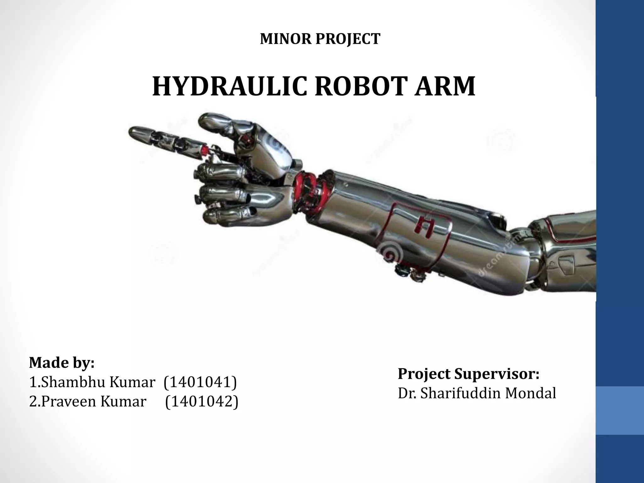
HYDRAULIC ROBOT ARM
Made by:
1.Shambhu Kumar (1401041)
2.Praveen Kumar (1401042)
Project Supervisor:
Dr. Sharifuddin Mondal
MINOR PROJECT
AGENDA
• Introduction to Robotics
• Fluid Power
• Hydraulic Liquids
• Hydraulic Lines an Fitting
• Hydraulic Cylinders
• Grippers
• Conclusion
Introduction
• Aim of the Project
• What are robots?
• Necessity of Robots
• Applications of Robots
Aim of the Project
• The aim of the project is to fabricate a hydraulic based model
of a robotic Arm capable of doing motion and lifting objects.
• To use the daily stationary and household items to fabricate
our model.
• To get an Insight in the world of robotics and make a base for
the future projects.
• To design a self dependent Hydraulic Robot arm system in
summer vacations by improving the current model.
Robotics
• Robot is a machine capable of
carrying out a complex series of
actions automatically, especially
one programmable by a computer
• Can be autonomous or
semiautonomous.
• The branch which deals in the
design and development is
Robotics
Ref. Honda
Applications:-
• Robots found applications in Military, commercial industries,
Medical Field, Education, Service sector , Space Engg. etc.
Military Applications Medical Applications
Ref. Google Images
Robotic arm
Robotic arm changing fuel rods at Nuclear
power plants
• Mechanical arm, usually programmable and having functions similar to Human
arm
• Found applications like pick and place, access uneven surfaces
and hazardous environments
Robotic arm deploying payload
from space shuttle
Fluid Power
• Fluids has got enormous power from dam to machines that can lift
bridges.
Ref. Google Images
• It can be harnessed in robotic arm with the help of hydraulics
• The application of Hydraulics ranges from Industries to
agriculture.
Pascal’s Law
• A change occurring anywhere in a confined incompressible fluid is
transmitted through the fluid so that same change occurs everywhere.
• Pascal Law is used in car lifters and
is the basic principle for all fluid
power machines
Mathematically,
P1 =P2
F1 /A1= F2 / A2
Hence,
F2 =F1 *(A2 /A1)
If , A1 <<< A2
Then, F2 > F1
Hydraulic Fluids
• Hydraulic Fluids are the medium by which
power is transferred in hydraulic machinery.
• Desirable properties
1. Viscosity
2. Lubricating power
3. Chemical Stability
4. Freedom from acidity
5. Minimum Toxicity
6. Cleanliness
• Types :
Petroleum Based
Synthetic Fire Resistant
Water based fire Resistant
Brake Fluid is also a Hydraulic Fluid
Hydraulic Cylinder
• Mechanical actuator used to give unidirectional force through unidirectional
stroke.
Cutaway portion of a Welded Body Hydraulic Cylinder
Main Parts:
• Cylinder Barrel
• Cylinder Base or Cap
• Cylinder Head
• Piston
• Piston rod
• Rod Gland
• Syringes has been used as the hydraulic cylinder for our project.
Tie Rod Cylinder
Hydraulic Lines and Fittings
• Provides a medium of
transfer of fluid power
from one point to another
in the system.
• Types of Lines
1. Pipe (Rigid)
2. Tubing (Semi Rigid)
3. Hose (Flexible)
• Materials Used are
Steel – Strength, Cost Effective and adaptability to high pressures.
Copper - High resistance to corrosion
Aluminum – Non corrosive, easily to draw or bent,Low weight
Rubber and composites
• In our project we have used plastic ducts to transfer fluid power.
Grippers:
• Used to grasp and hold objects,
usually the work piece.
• The applications include machine
loading and unloading,
picking parts from a conveyer and
arranging the parts.
• Types of grippers:
1.Mechanical
2. Adhesive
3. Hooks, Scoops etc.
4. Vaccum Cups
5. Magnetic Grippers A simple Robotic Gripper design
Conclusion
• Our design uses simple ideas and mechanisms to achieve the motion.
• Such Hydraulic robot arms may be costlier for small scale industries but
it’s cost can be justified with increased production rates.
• Current Robotic Arm Hardware need many improvements in design and
fabrication .It is just a proof of concept.
• Innovations/Improvements
--- use of microcontroller and a compressor to automate the hand
operation
--- Machine Vision and AI can be used to make the arm self dependent
and perform the task without any human intervention.
--- An innovative design involve jaws that change their orientation
to the shape of the object.
References
• http://sciencekit.com/teacher-geek-hydraulics-pneumatics/c/1091955/
• http://en.wikipedia.org/wiki/Hydraulic_cylinder
• http://enginemechanics.tpub.com/14105/
• http://www.howstuffworks.com/transport/enginesequipment/hydraulic.ht
m
• A text book of Fluid Mechanics by R.K. Bansal
• All images were taken from Google Images
Thank
You

Hydraulic Based Robotic Arm

  • 1.
    HYDRAULIC ROBOT ARM Madeby: 1.Shambhu Kumar (1401041) 2.Praveen Kumar (1401042) Project Supervisor: Dr. Sharifuddin Mondal MINOR PROJECT
  • 2.
    AGENDA • Introduction toRobotics • Fluid Power • Hydraulic Liquids • Hydraulic Lines an Fitting • Hydraulic Cylinders • Grippers • Conclusion
  • 3.
    Introduction • Aim ofthe Project • What are robots? • Necessity of Robots • Applications of Robots
  • 4.
    Aim of theProject • The aim of the project is to fabricate a hydraulic based model of a robotic Arm capable of doing motion and lifting objects. • To use the daily stationary and household items to fabricate our model. • To get an Insight in the world of robotics and make a base for the future projects. • To design a self dependent Hydraulic Robot arm system in summer vacations by improving the current model.
  • 5.
    Robotics • Robot isa machine capable of carrying out a complex series of actions automatically, especially one programmable by a computer • Can be autonomous or semiautonomous. • The branch which deals in the design and development is Robotics Ref. Honda
  • 6.
    Applications:- • Robots foundapplications in Military, commercial industries, Medical Field, Education, Service sector , Space Engg. etc. Military Applications Medical Applications Ref. Google Images
  • 7.
    Robotic arm Robotic armchanging fuel rods at Nuclear power plants • Mechanical arm, usually programmable and having functions similar to Human arm • Found applications like pick and place, access uneven surfaces and hazardous environments Robotic arm deploying payload from space shuttle
  • 8.
    Fluid Power • Fluidshas got enormous power from dam to machines that can lift bridges. Ref. Google Images • It can be harnessed in robotic arm with the help of hydraulics • The application of Hydraulics ranges from Industries to agriculture.
  • 9.
    Pascal’s Law • Achange occurring anywhere in a confined incompressible fluid is transmitted through the fluid so that same change occurs everywhere. • Pascal Law is used in car lifters and is the basic principle for all fluid power machines Mathematically, P1 =P2 F1 /A1= F2 / A2 Hence, F2 =F1 *(A2 /A1) If , A1 <<< A2 Then, F2 > F1
  • 10.
    Hydraulic Fluids • HydraulicFluids are the medium by which power is transferred in hydraulic machinery. • Desirable properties 1. Viscosity 2. Lubricating power 3. Chemical Stability 4. Freedom from acidity 5. Minimum Toxicity 6. Cleanliness • Types : Petroleum Based Synthetic Fire Resistant Water based fire Resistant Brake Fluid is also a Hydraulic Fluid
  • 11.
    Hydraulic Cylinder • Mechanicalactuator used to give unidirectional force through unidirectional stroke. Cutaway portion of a Welded Body Hydraulic Cylinder Main Parts: • Cylinder Barrel • Cylinder Base or Cap • Cylinder Head • Piston • Piston rod • Rod Gland • Syringes has been used as the hydraulic cylinder for our project. Tie Rod Cylinder
  • 12.
    Hydraulic Lines andFittings • Provides a medium of transfer of fluid power from one point to another in the system. • Types of Lines 1. Pipe (Rigid) 2. Tubing (Semi Rigid) 3. Hose (Flexible) • Materials Used are Steel – Strength, Cost Effective and adaptability to high pressures. Copper - High resistance to corrosion Aluminum – Non corrosive, easily to draw or bent,Low weight Rubber and composites • In our project we have used plastic ducts to transfer fluid power.
  • 13.
    Grippers: • Used tograsp and hold objects, usually the work piece. • The applications include machine loading and unloading, picking parts from a conveyer and arranging the parts. • Types of grippers: 1.Mechanical 2. Adhesive 3. Hooks, Scoops etc. 4. Vaccum Cups 5. Magnetic Grippers A simple Robotic Gripper design
  • 14.
    Conclusion • Our designuses simple ideas and mechanisms to achieve the motion. • Such Hydraulic robot arms may be costlier for small scale industries but it’s cost can be justified with increased production rates. • Current Robotic Arm Hardware need many improvements in design and fabrication .It is just a proof of concept. • Innovations/Improvements --- use of microcontroller and a compressor to automate the hand operation --- Machine Vision and AI can be used to make the arm self dependent and perform the task without any human intervention. --- An innovative design involve jaws that change their orientation to the shape of the object.
  • 15.
    References • http://sciencekit.com/teacher-geek-hydraulics-pneumatics/c/1091955/ • http://en.wikipedia.org/wiki/Hydraulic_cylinder •http://enginemechanics.tpub.com/14105/ • http://www.howstuffworks.com/transport/enginesequipment/hydraulic.ht m • A text book of Fluid Mechanics by R.K. Bansal • All images were taken from Google Images
  • 16.