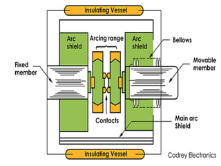
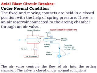
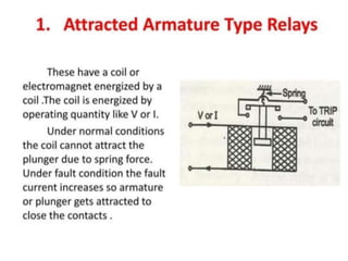
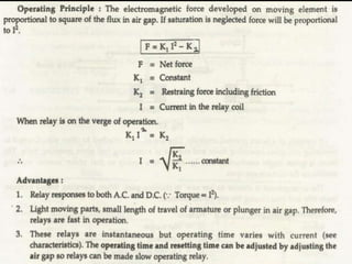
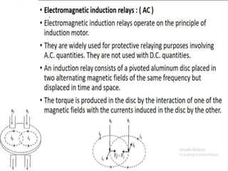
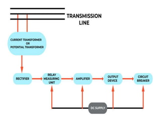
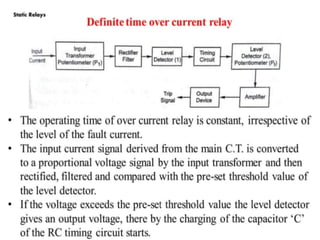
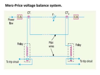
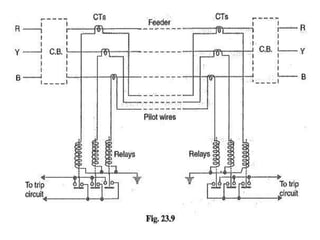
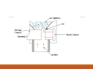
This document discusses different types of circuit breakers including high resistance, low resistance, SF6, and minimum oil circuit breakers. It provides details on their construction, working principles, and advantages. The high resistance method works by increasing the arc resistance to reduce current. The low resistance method uses AC current zero crossings to extinguish arcs. SF6 breakers use sulfur hexafluoride gas to absorb electrons in arcs. Minimum oil breakers use a small amount of oil and pressure to quickly extinguish arcs.


![Rate of Rise of Re-striking Voltage (RRRV):
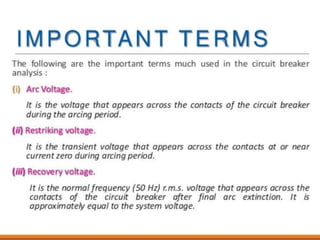
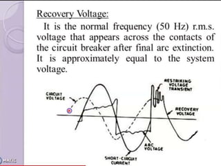
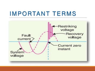
The transient voltage that appears across the contacts of the circuit breaker
at the current zero period during arcing is known as Restriking voltage.
The expression for the re-striking voltage is VC( t ) = Vm(1− cos ωnt )
The maximum value of the re-striking voltage occurs at t = π / ωn = π √ L C
The maximum value of re-striking voltage = 2 Vm = 2 × peak value of the
system voltage.
The rate of rise of re-striking voltage (RRRV) = d/dt [ Vm (1− cos ωnt ) ]
∴ RRRV = Vm ωn sin ωnt
The rate of rise of re-striking voltage is directly proportional to the natural
frequency.
R R R V ∝ ωn ∝ 1 √ L C
Where L is the inductance of the system
C is the capacitance of the system
So, the rate of rise of re-striking voltage (RRRV) is dependent upon both
the inductance and capacitance of the system.
Now, the maximum value of RRRV occurs when ωnt = π/2 i.e. when
t = π/2ωn
∴The maximum value of RRRV = V mω n = Vm / √ L C
RRRVmax = Vm / √ L C](https://image.slidesharecdn.com/vcbmaintenanceppt-240409183544-32f64175/85/HT-6-6-KV-VCB-OPERATION-AND-MAINTENANCE-PPT-25-320.jpg)