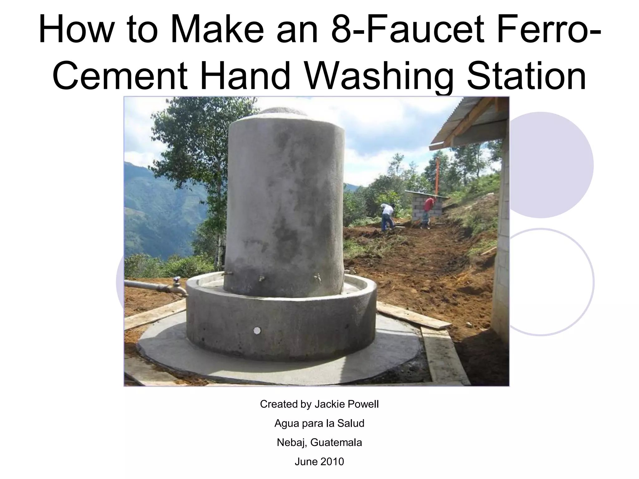
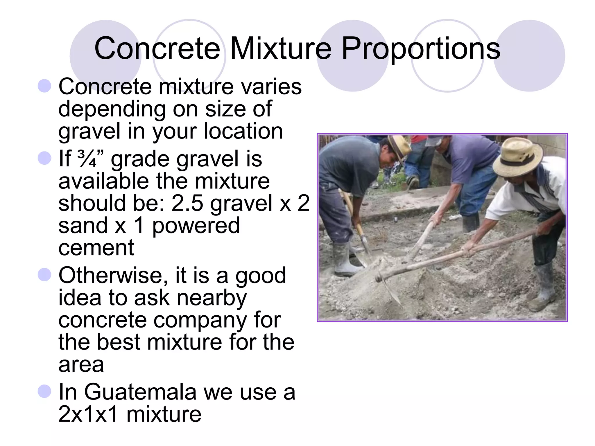
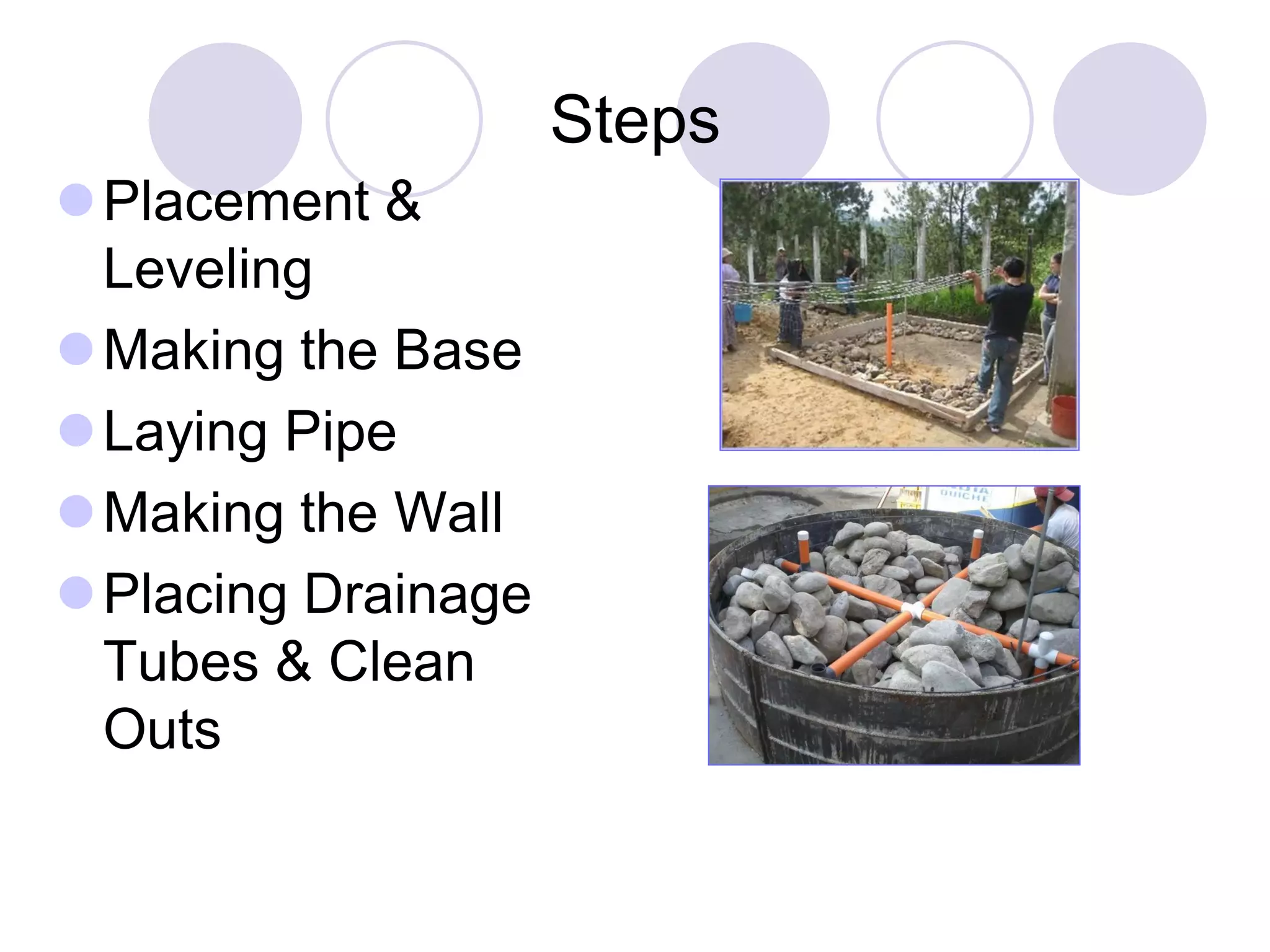
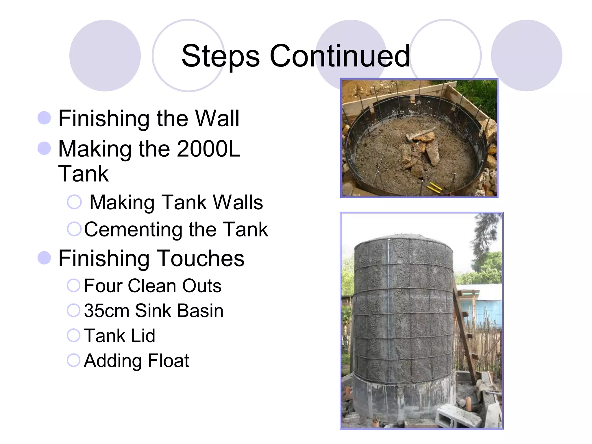
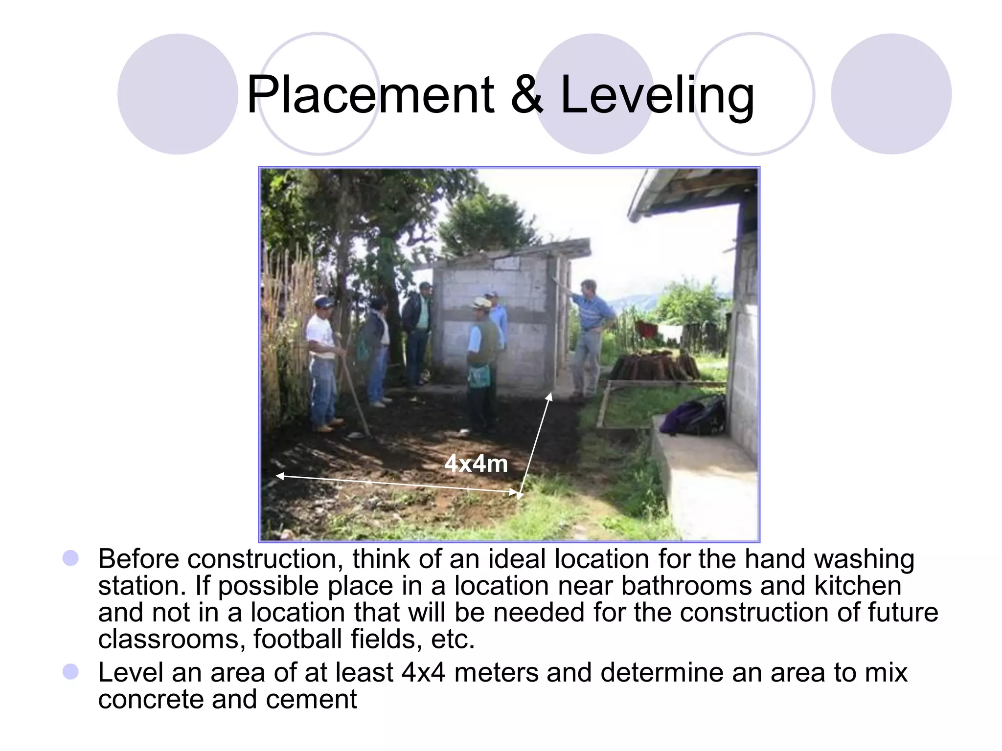
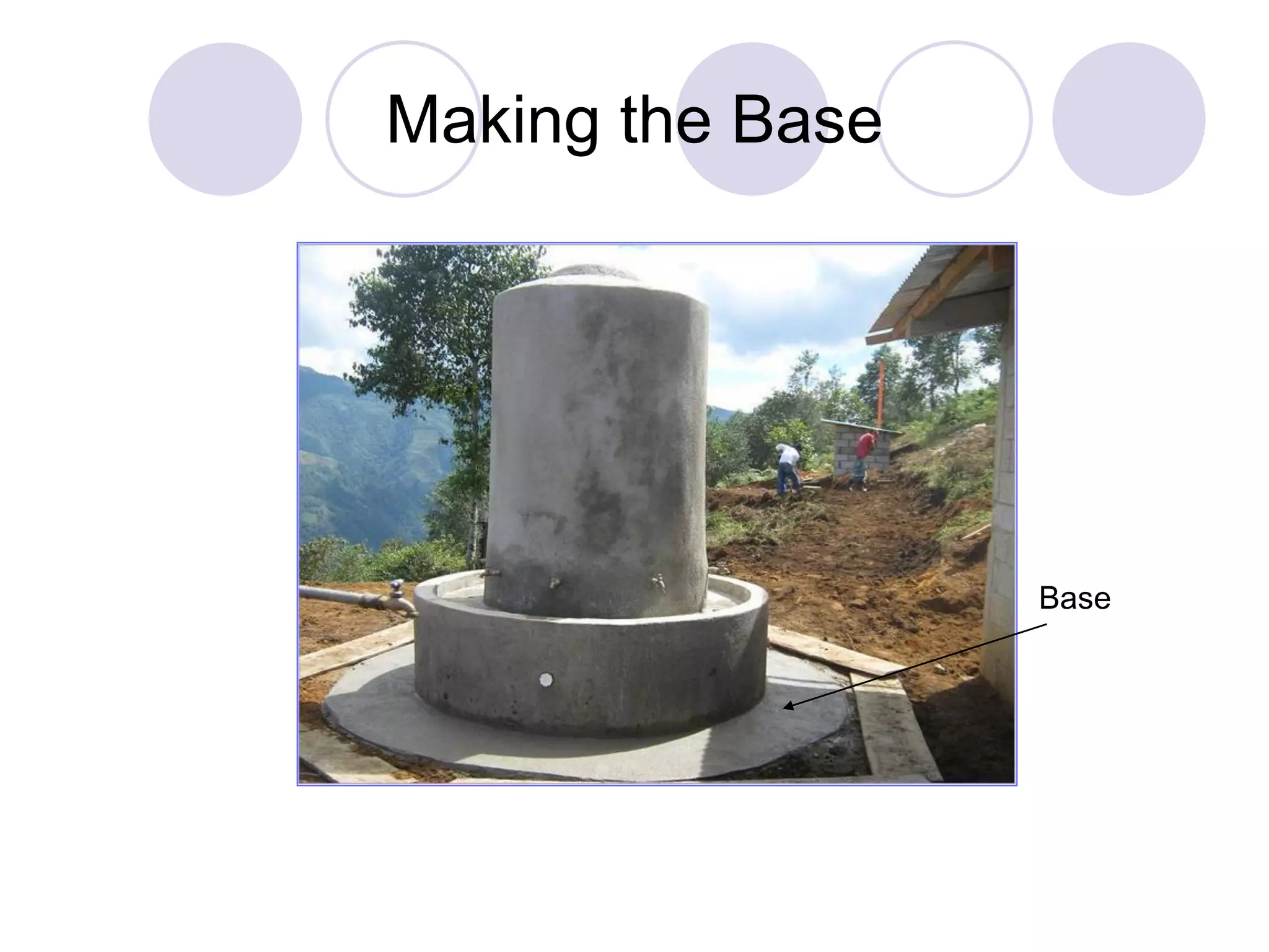
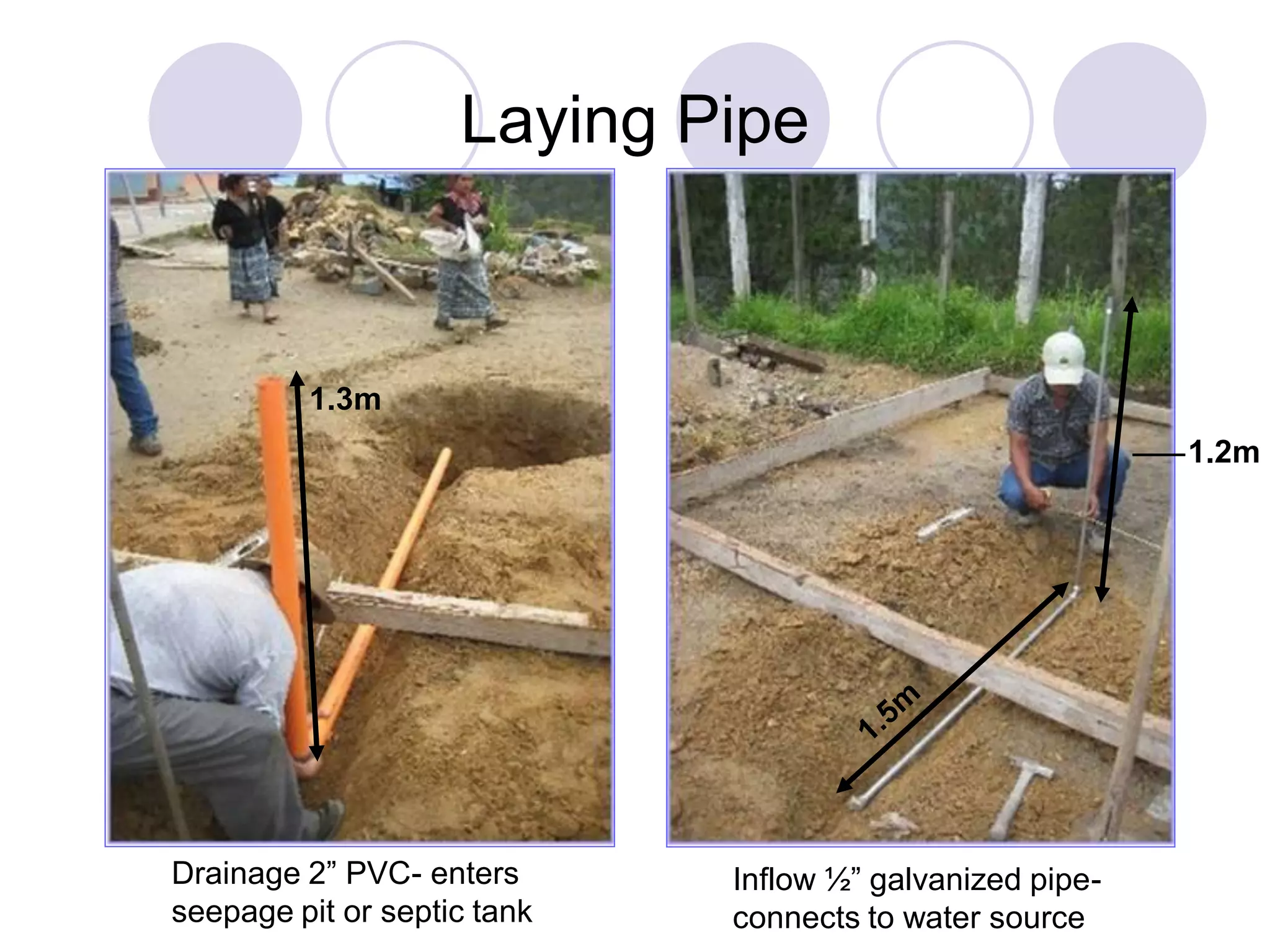
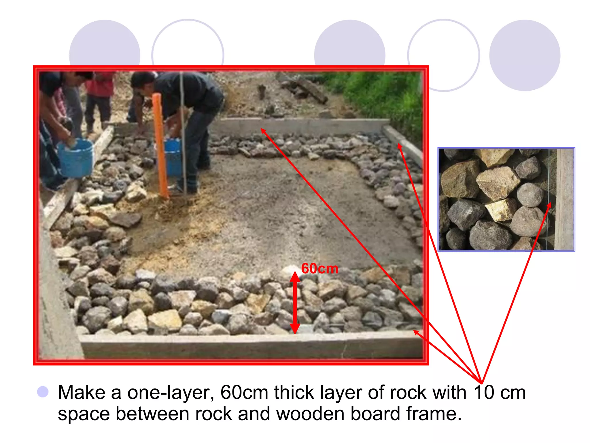
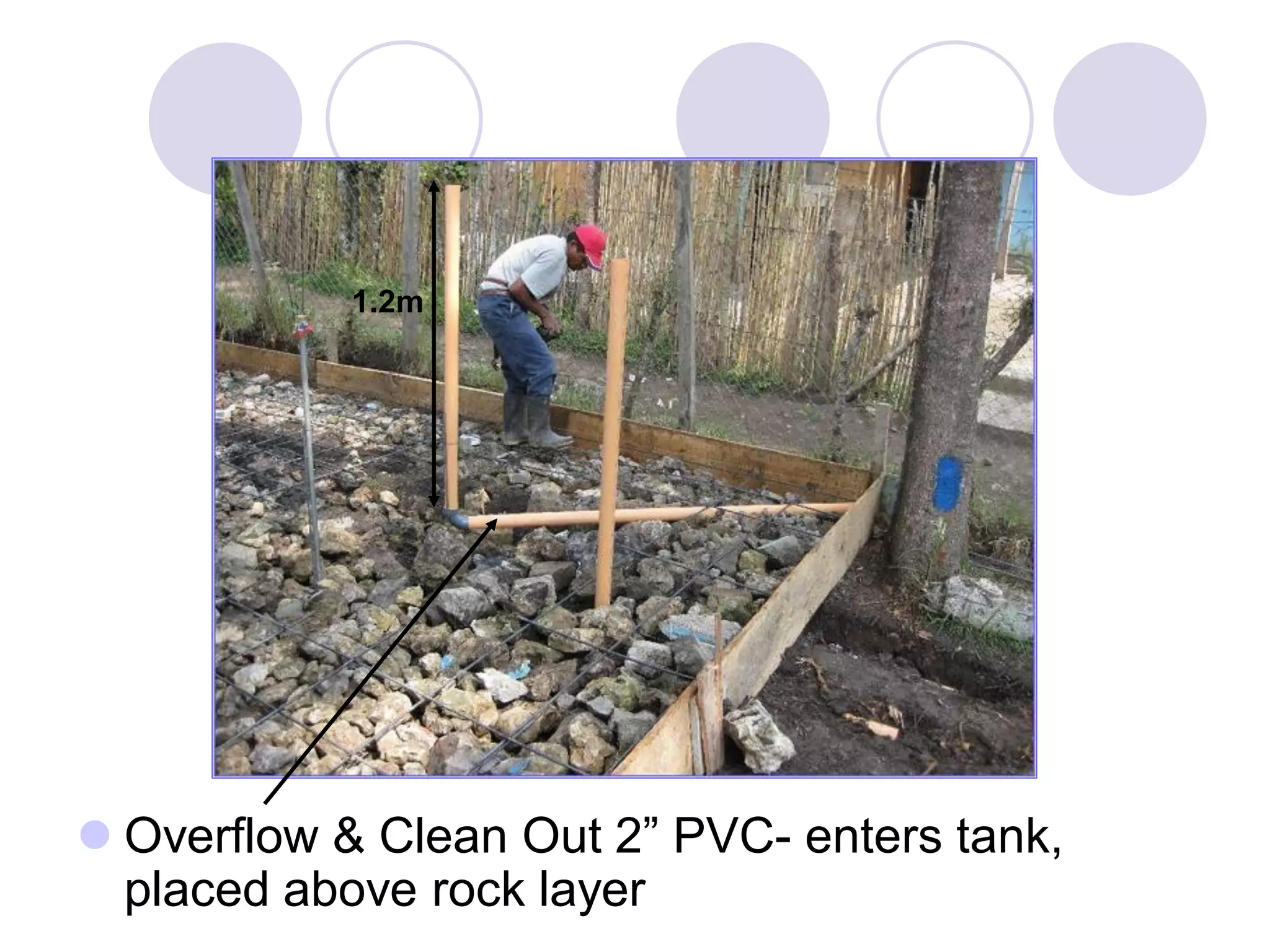
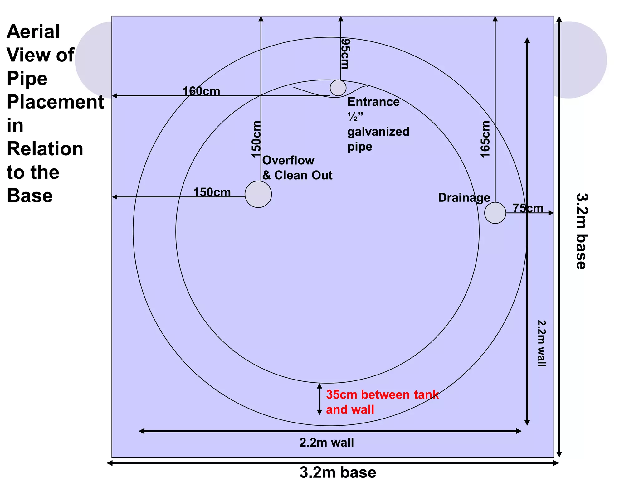
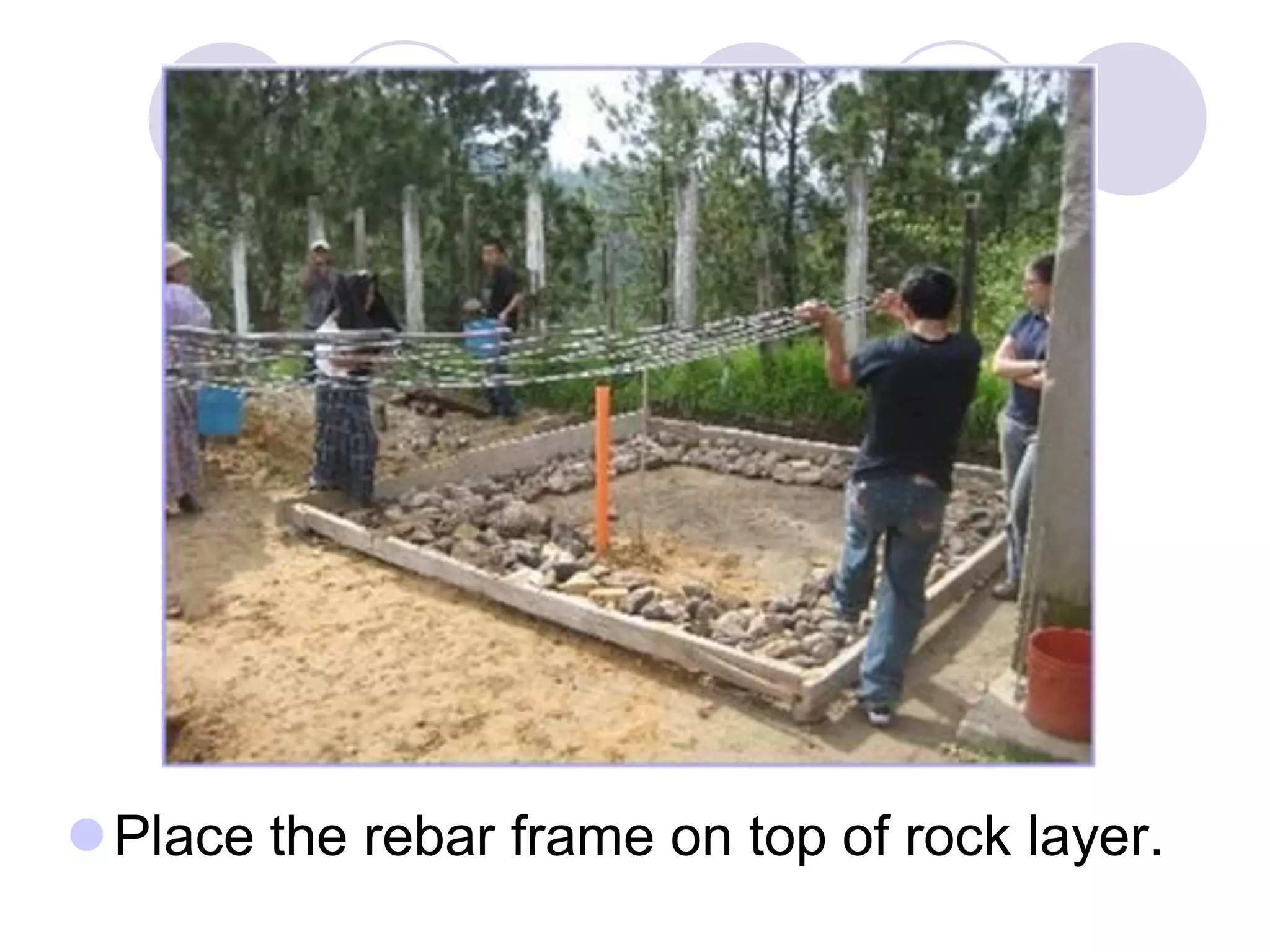
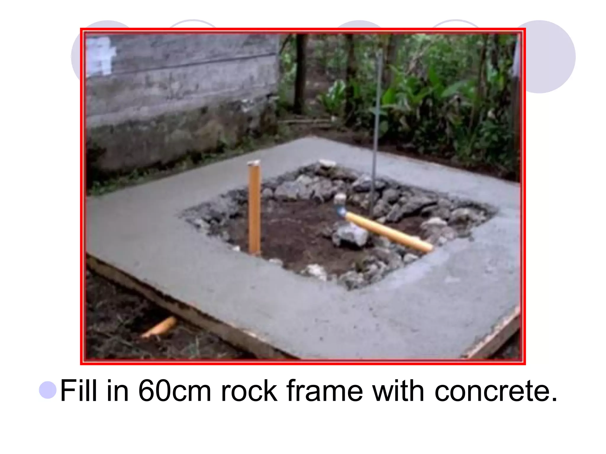
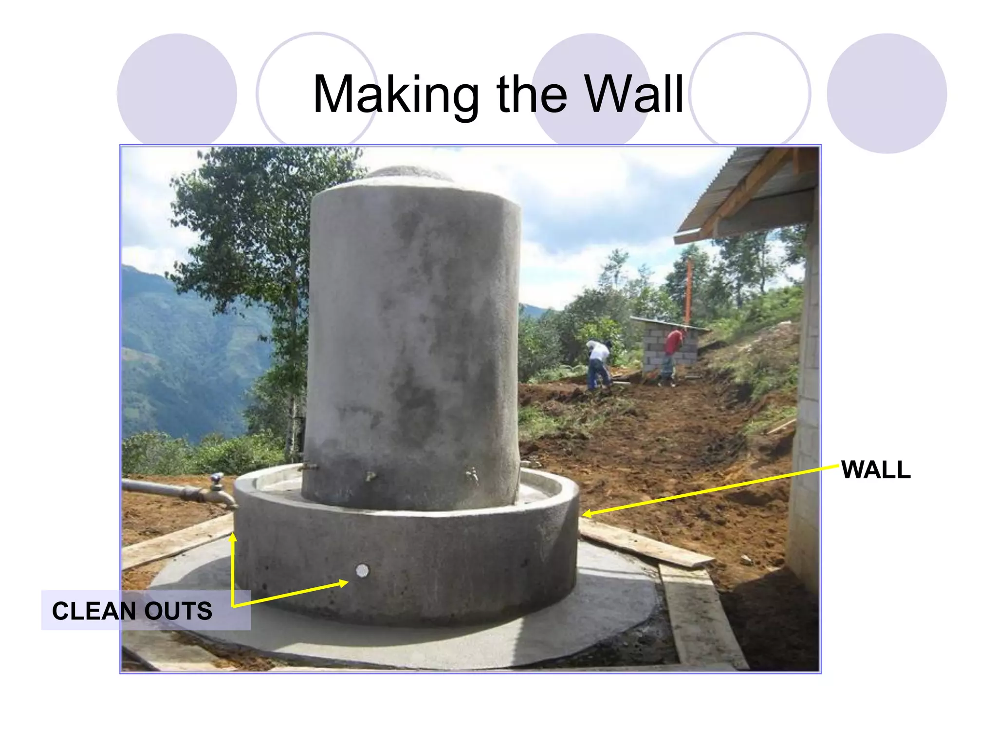
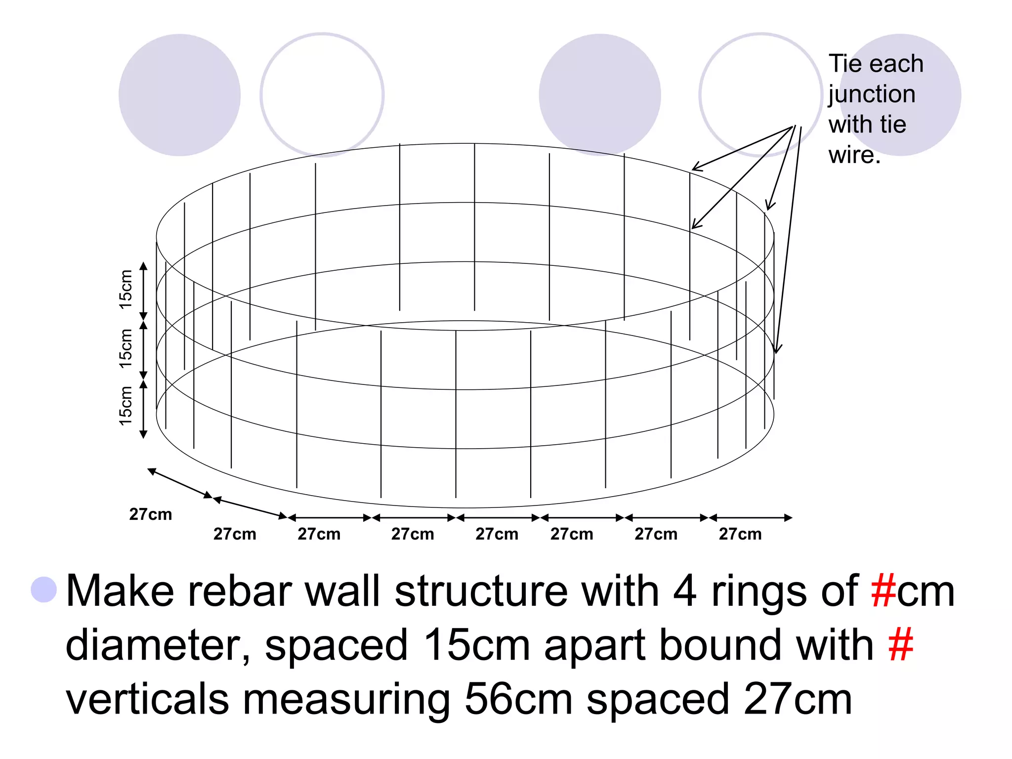
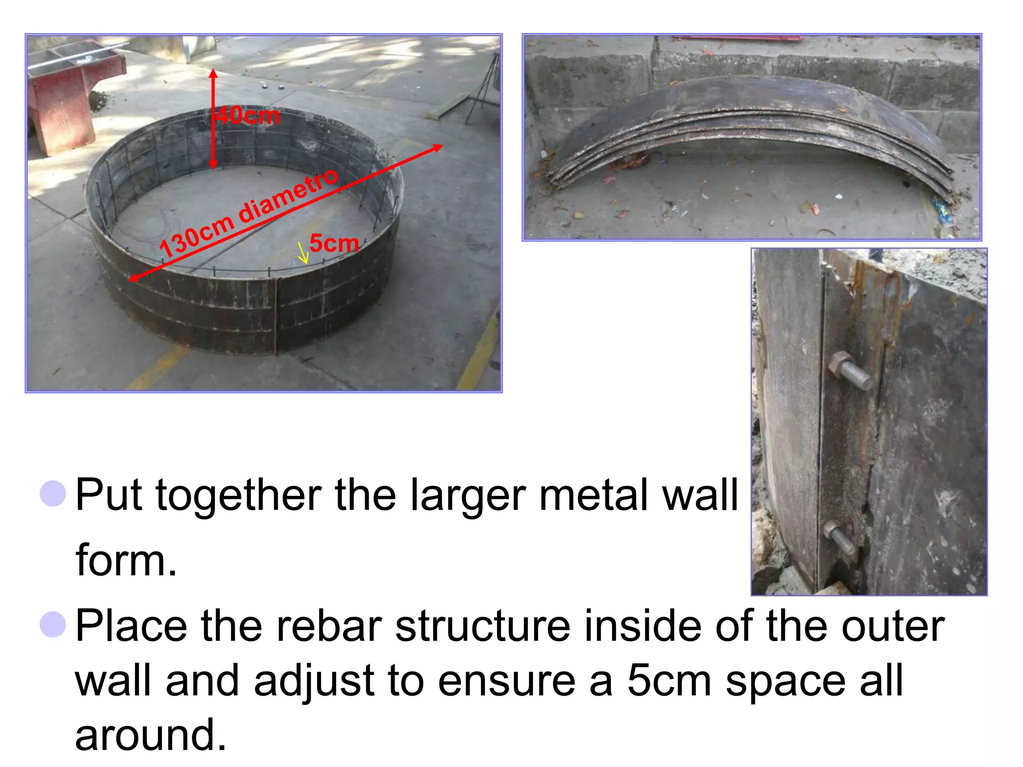
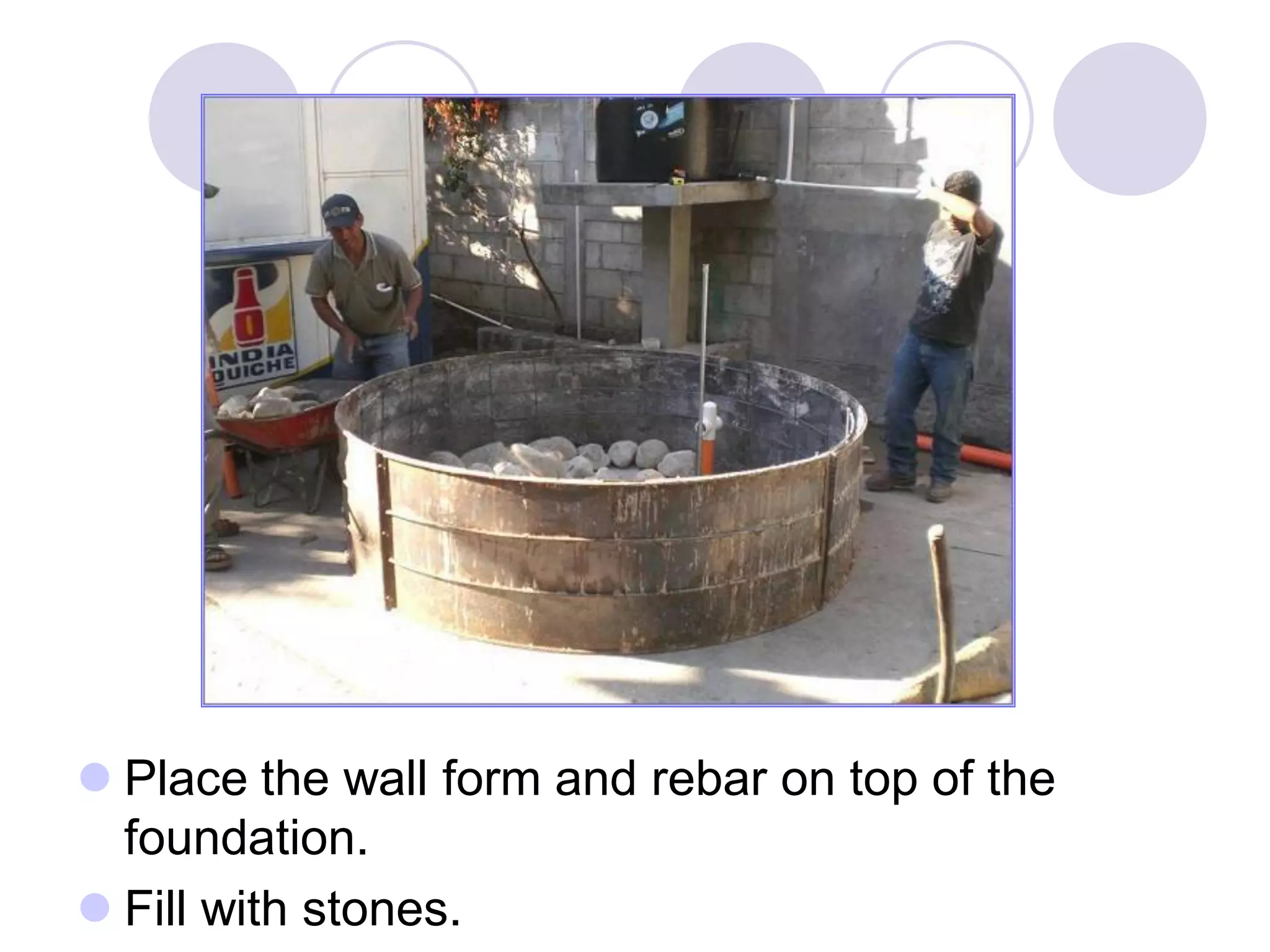
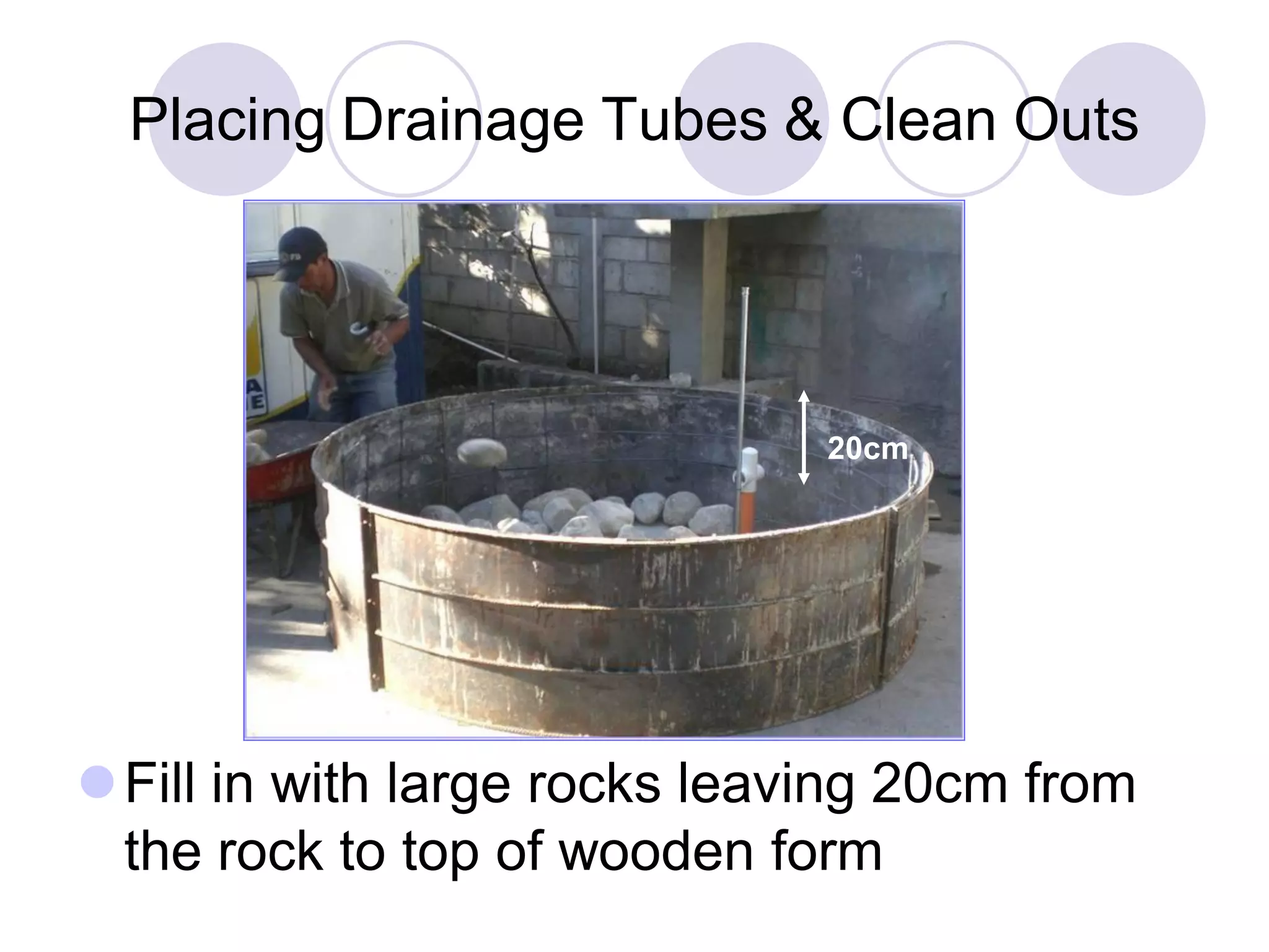
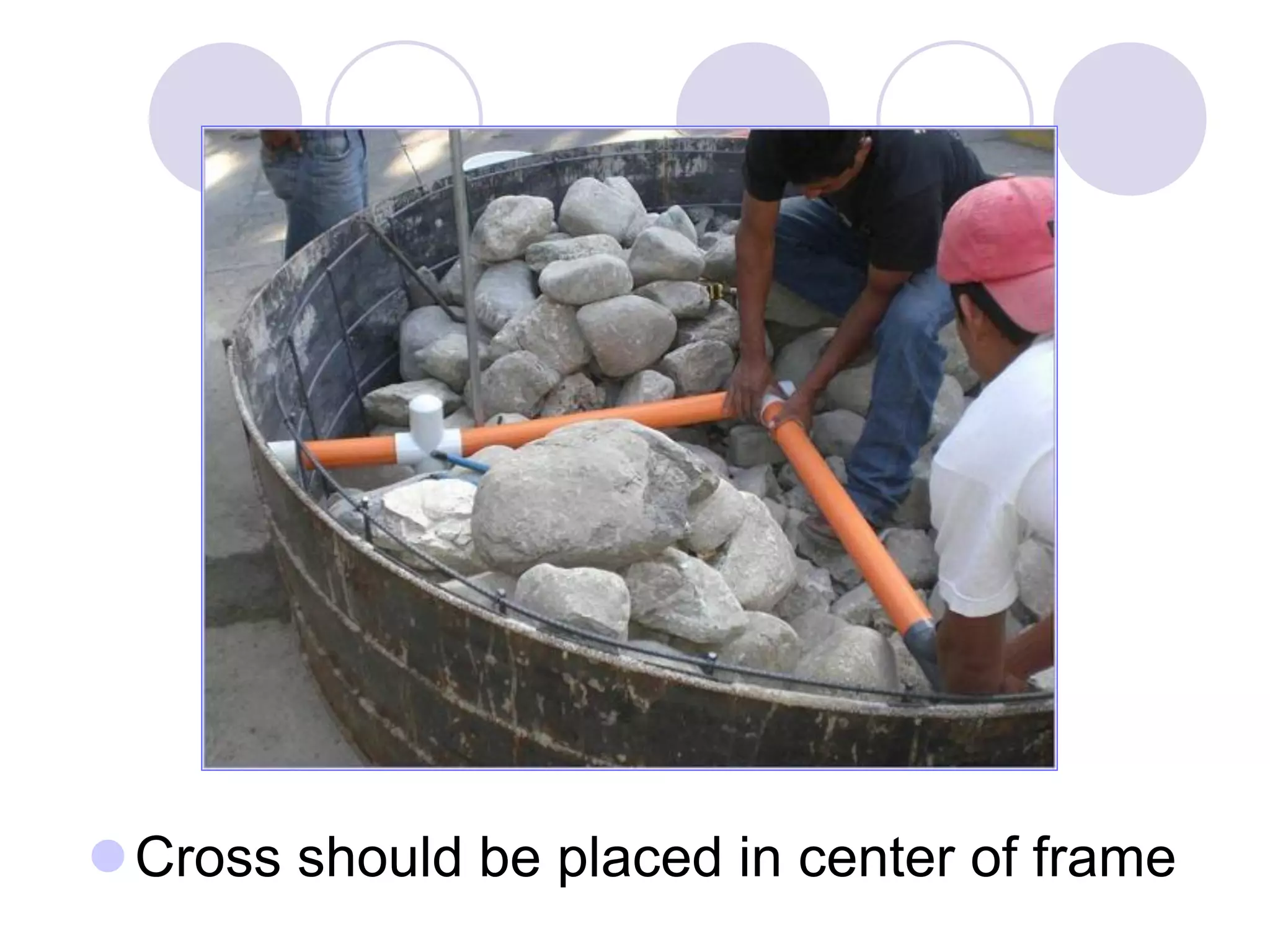
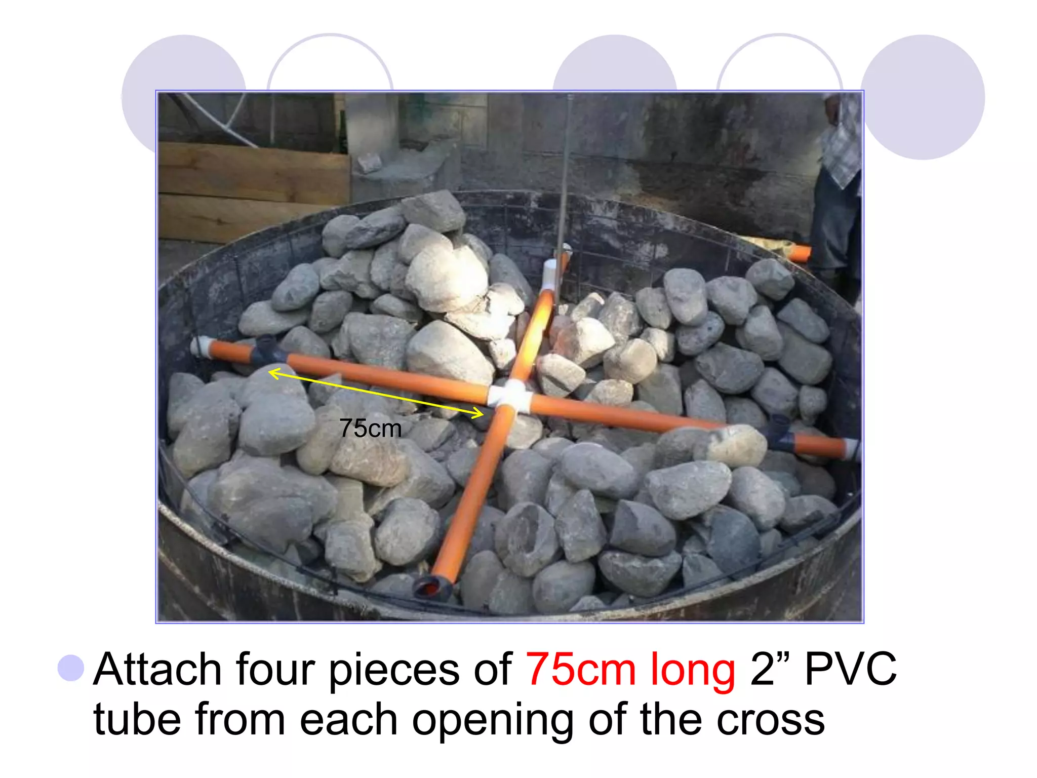
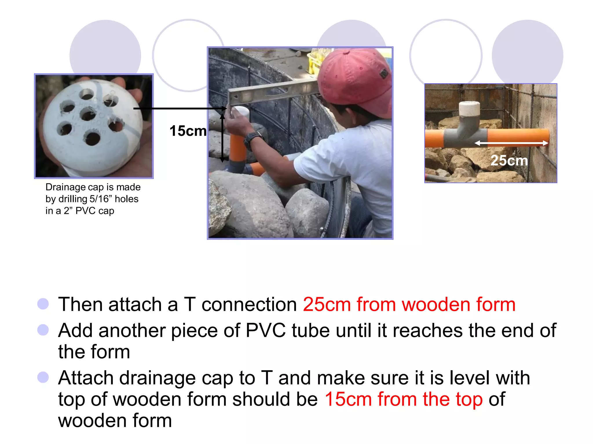
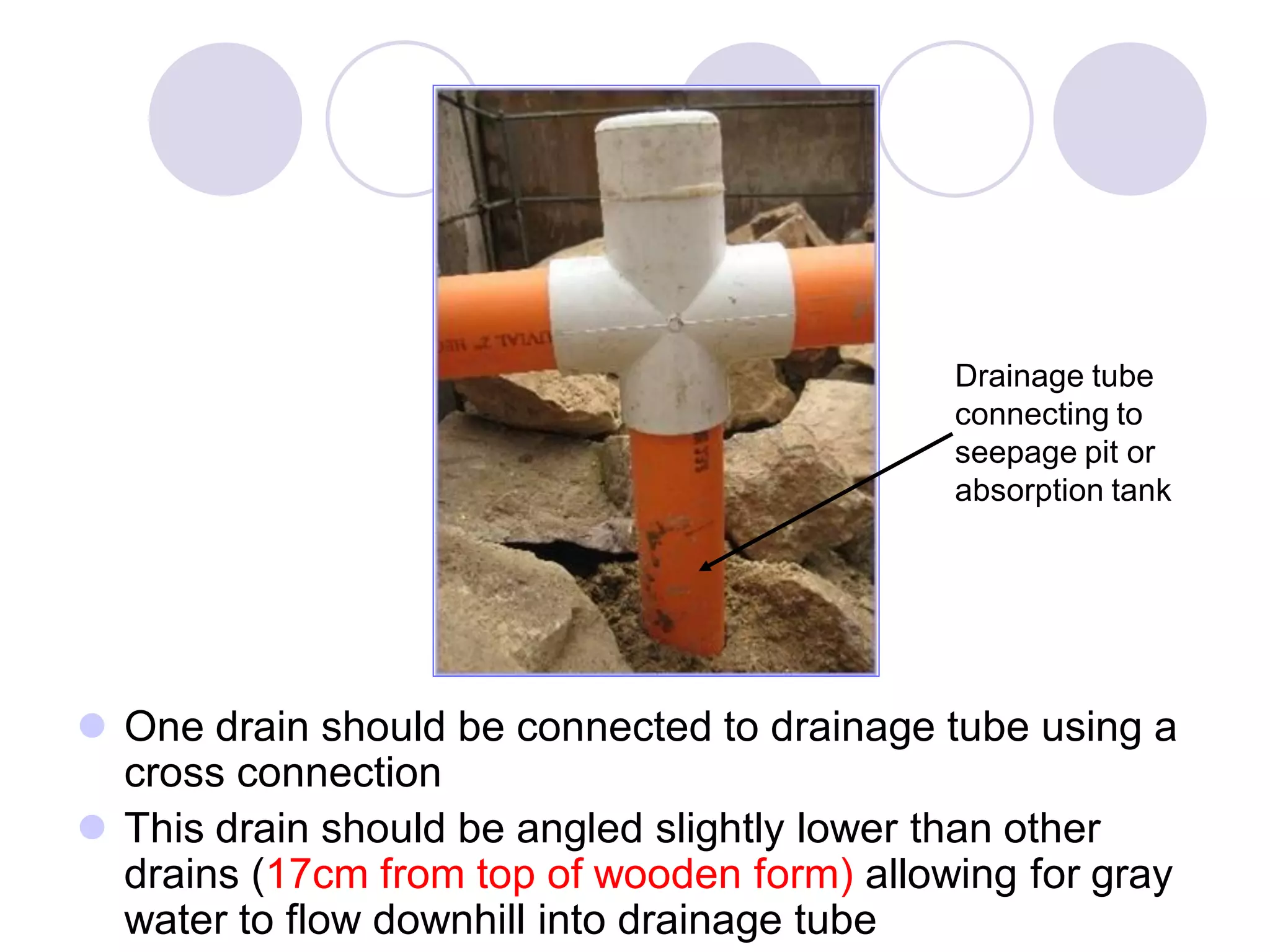
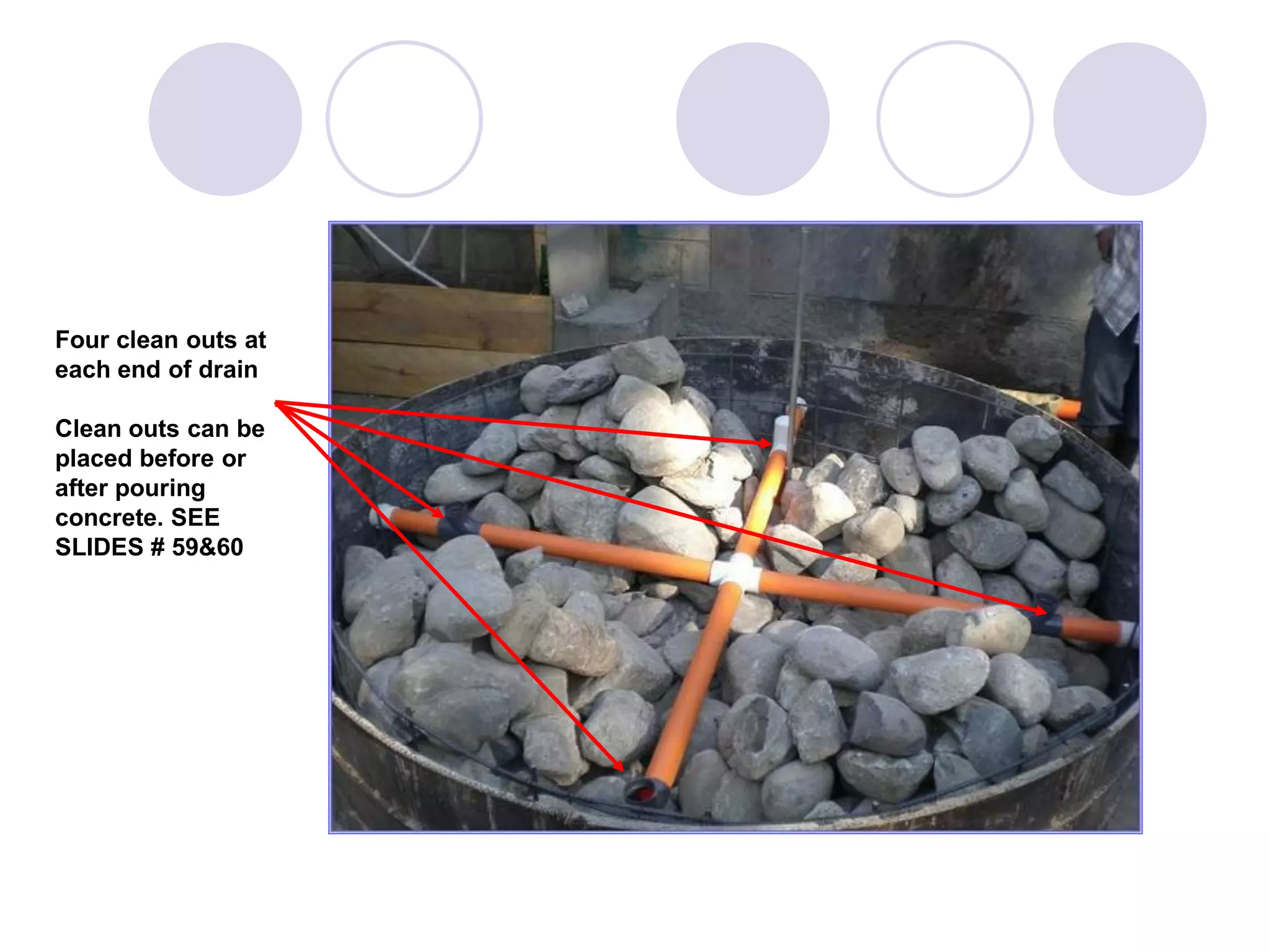
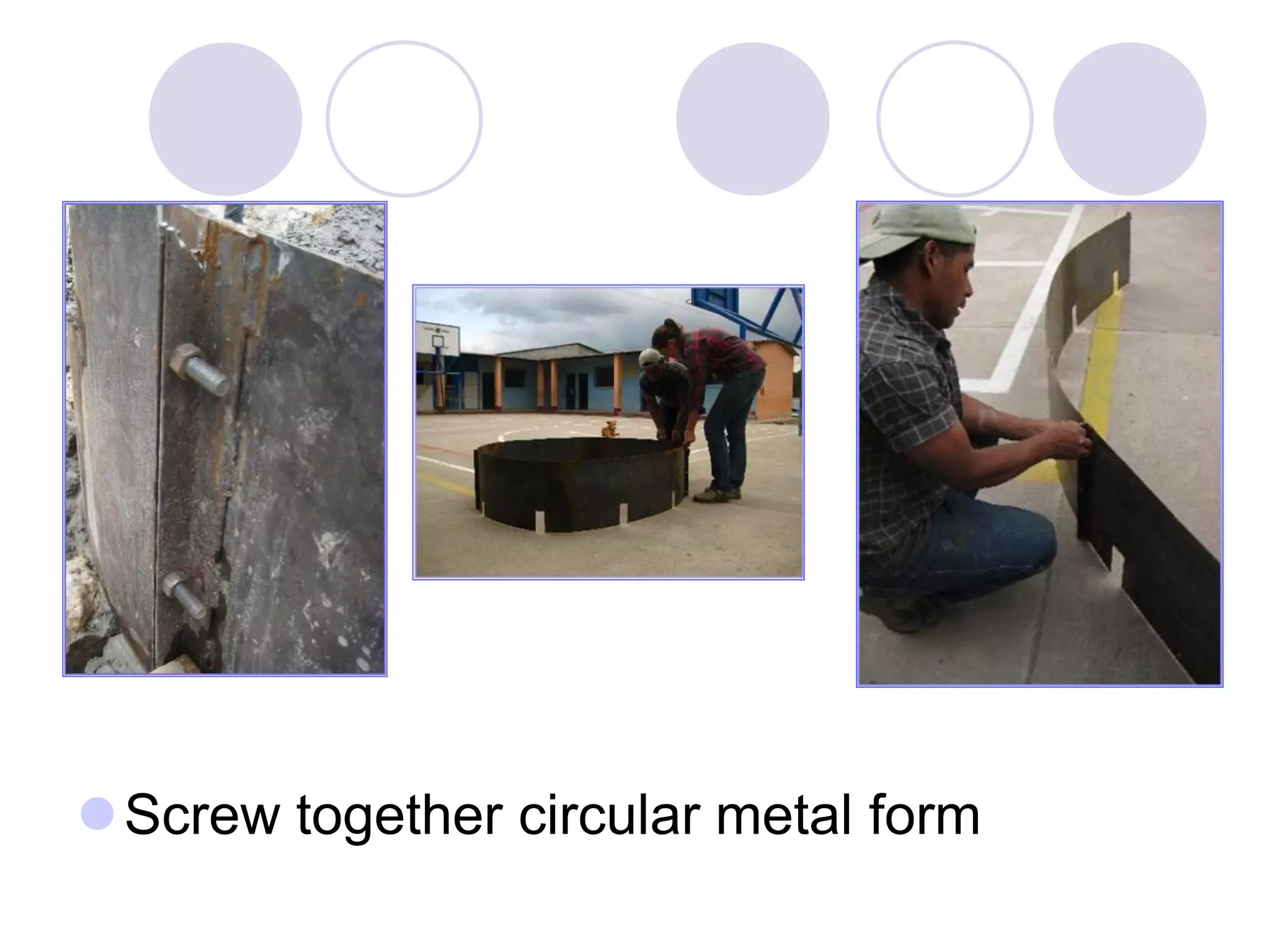
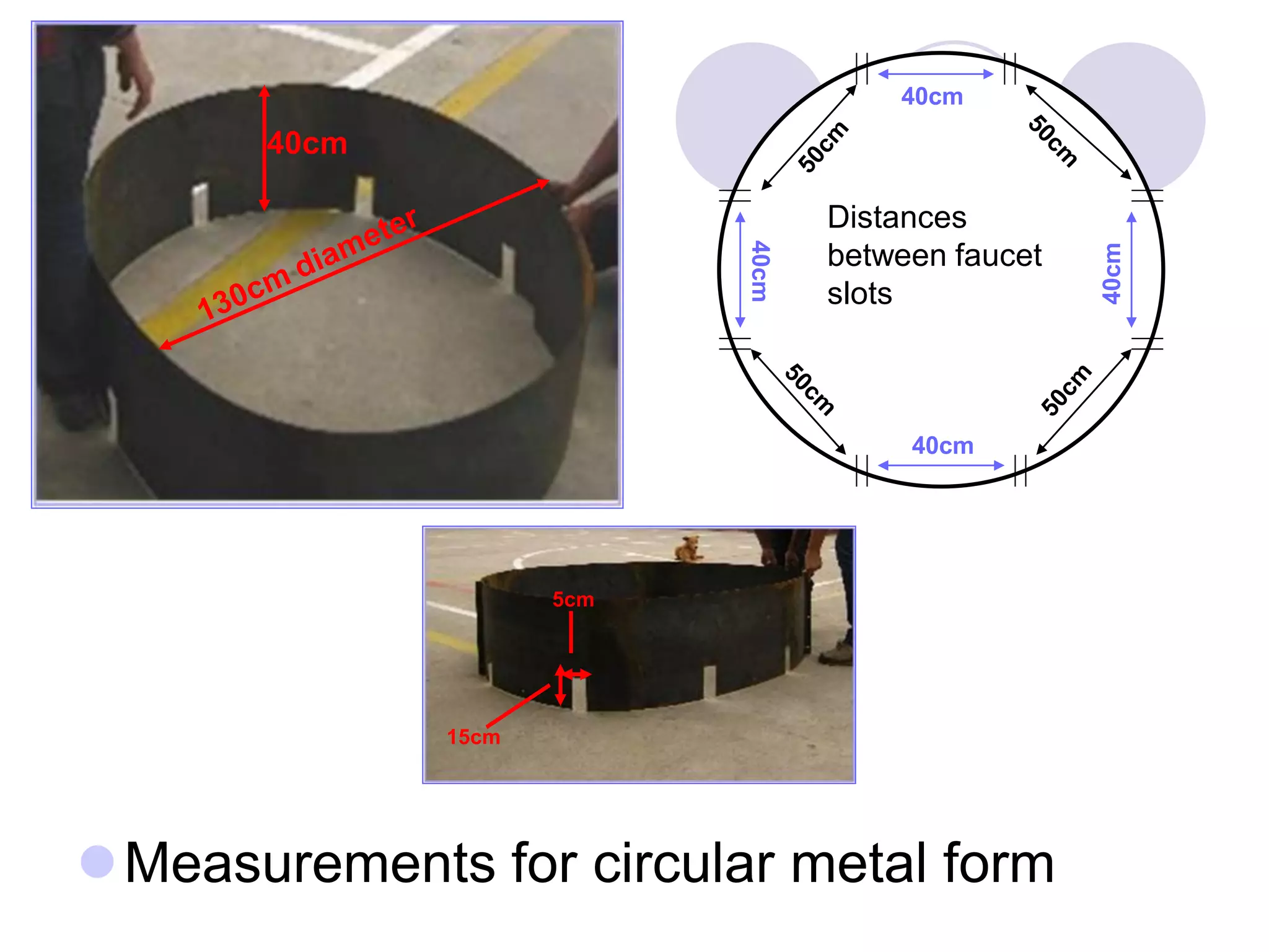
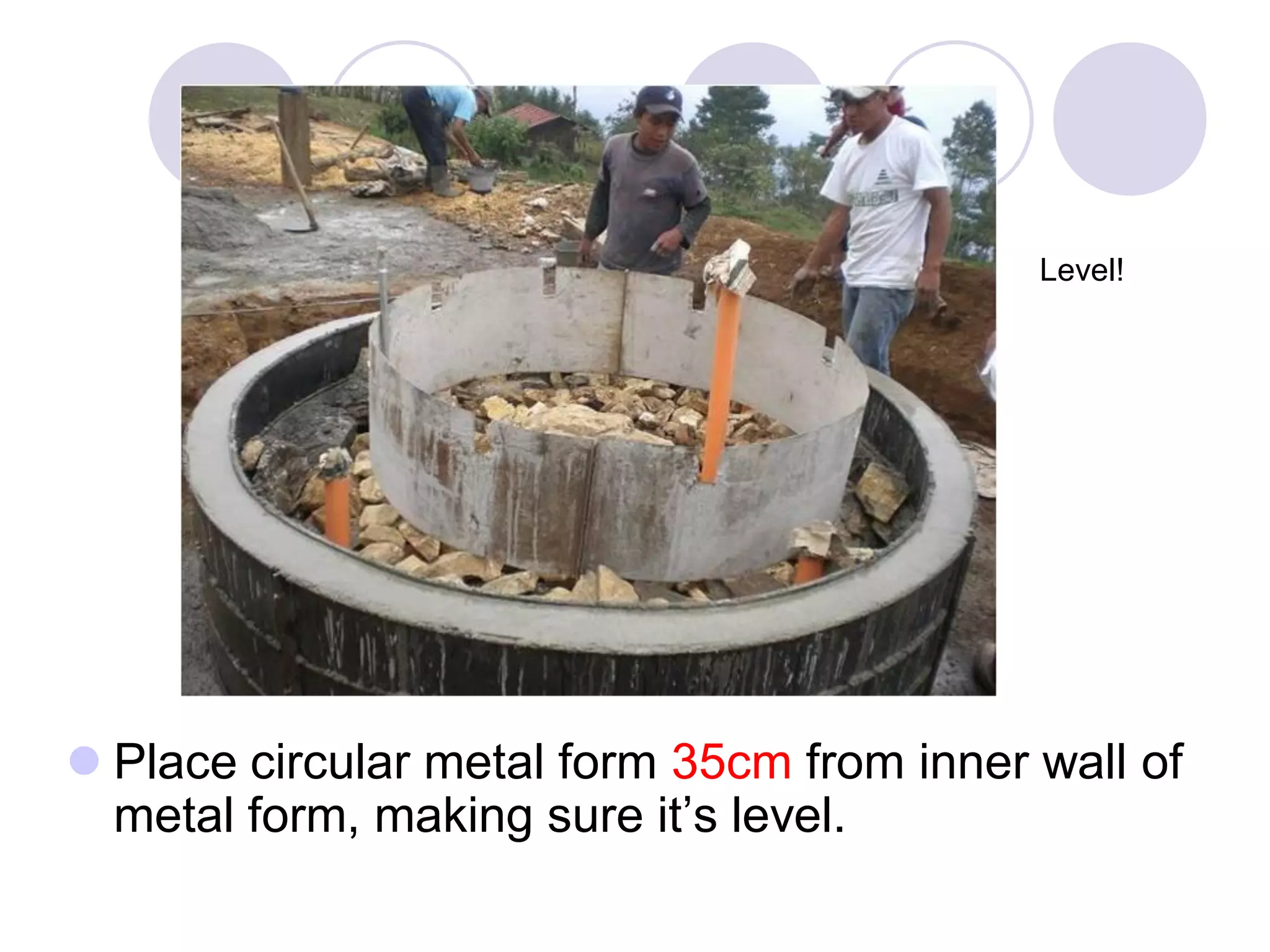
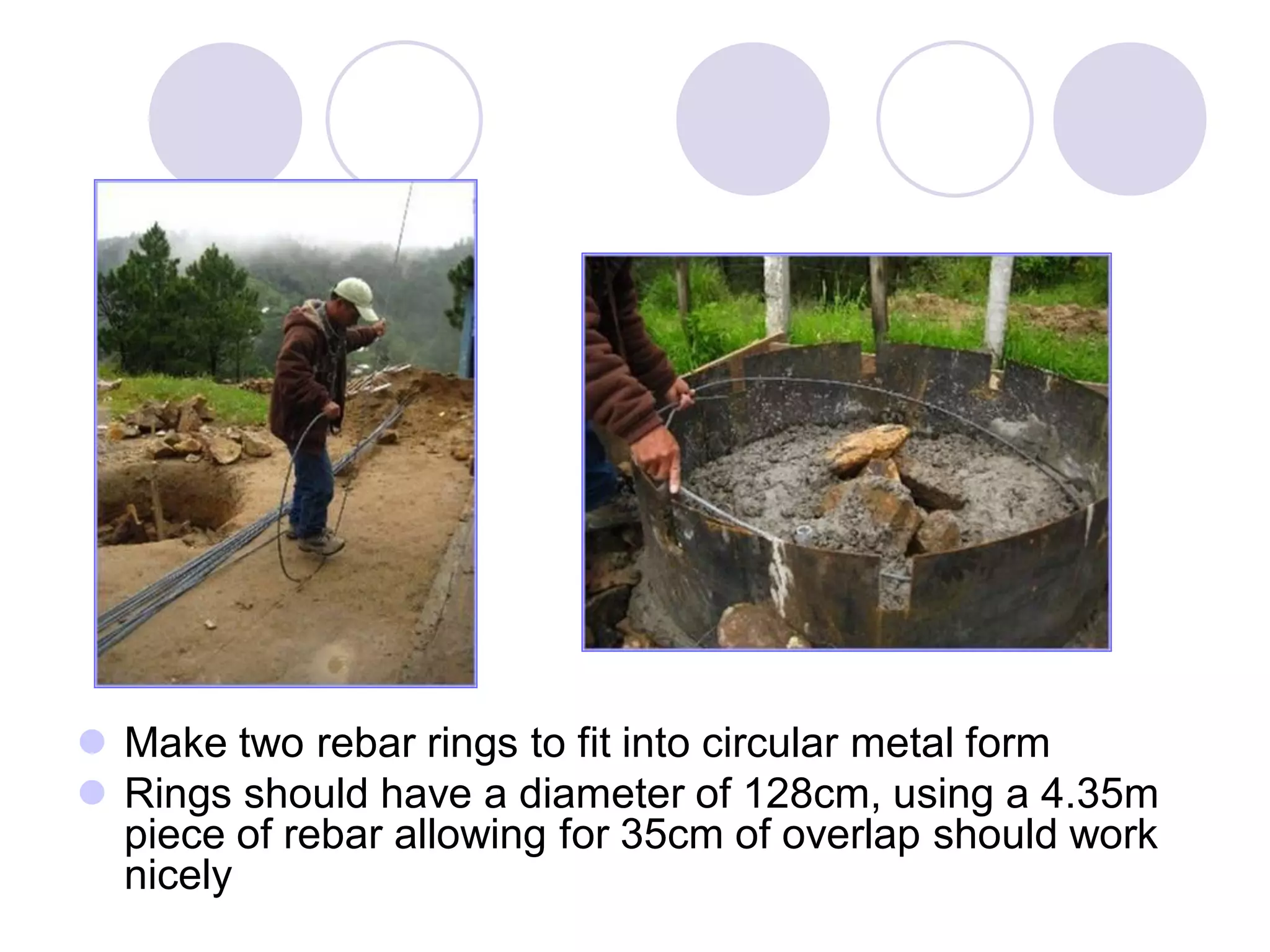
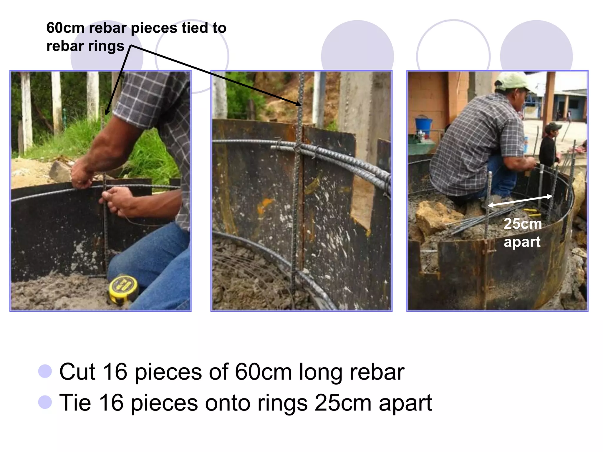
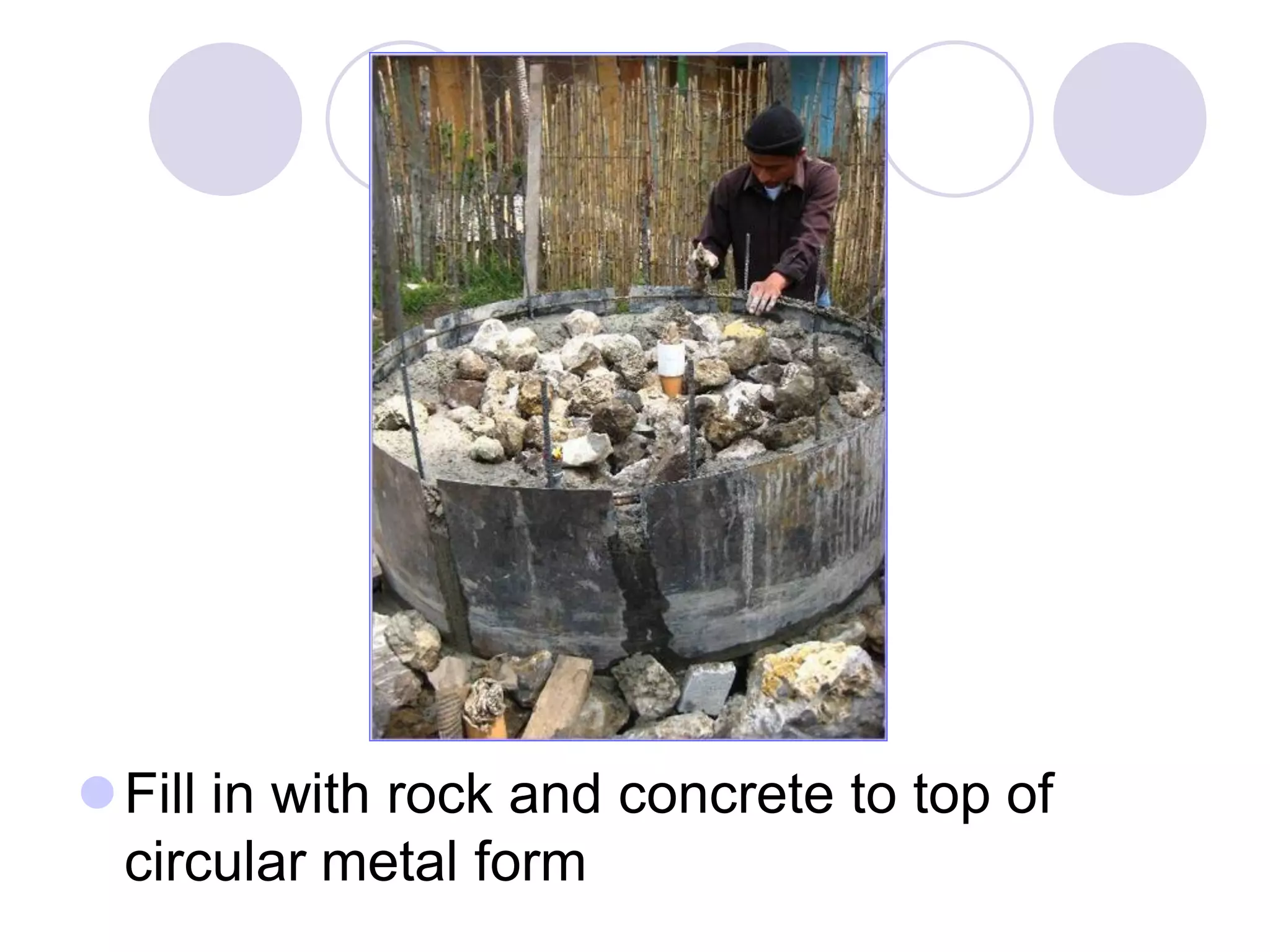
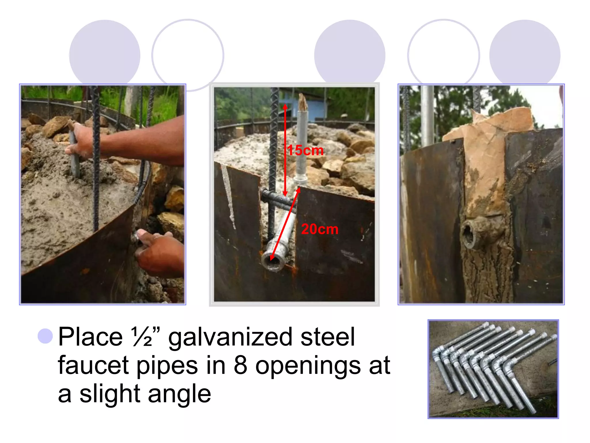
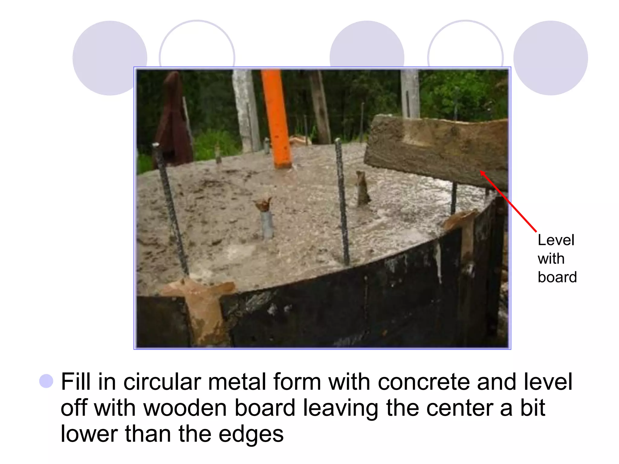
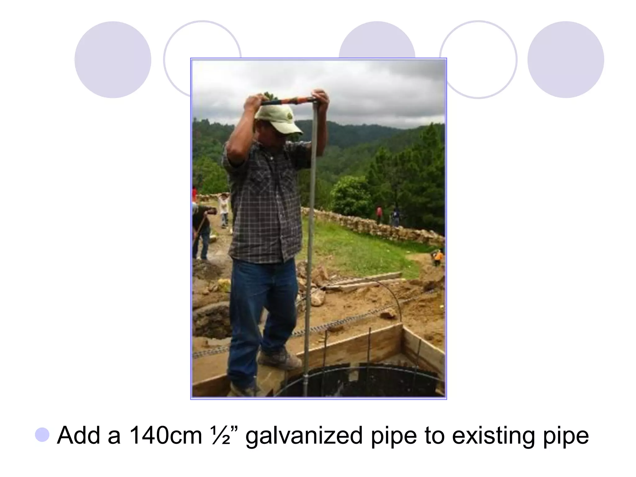
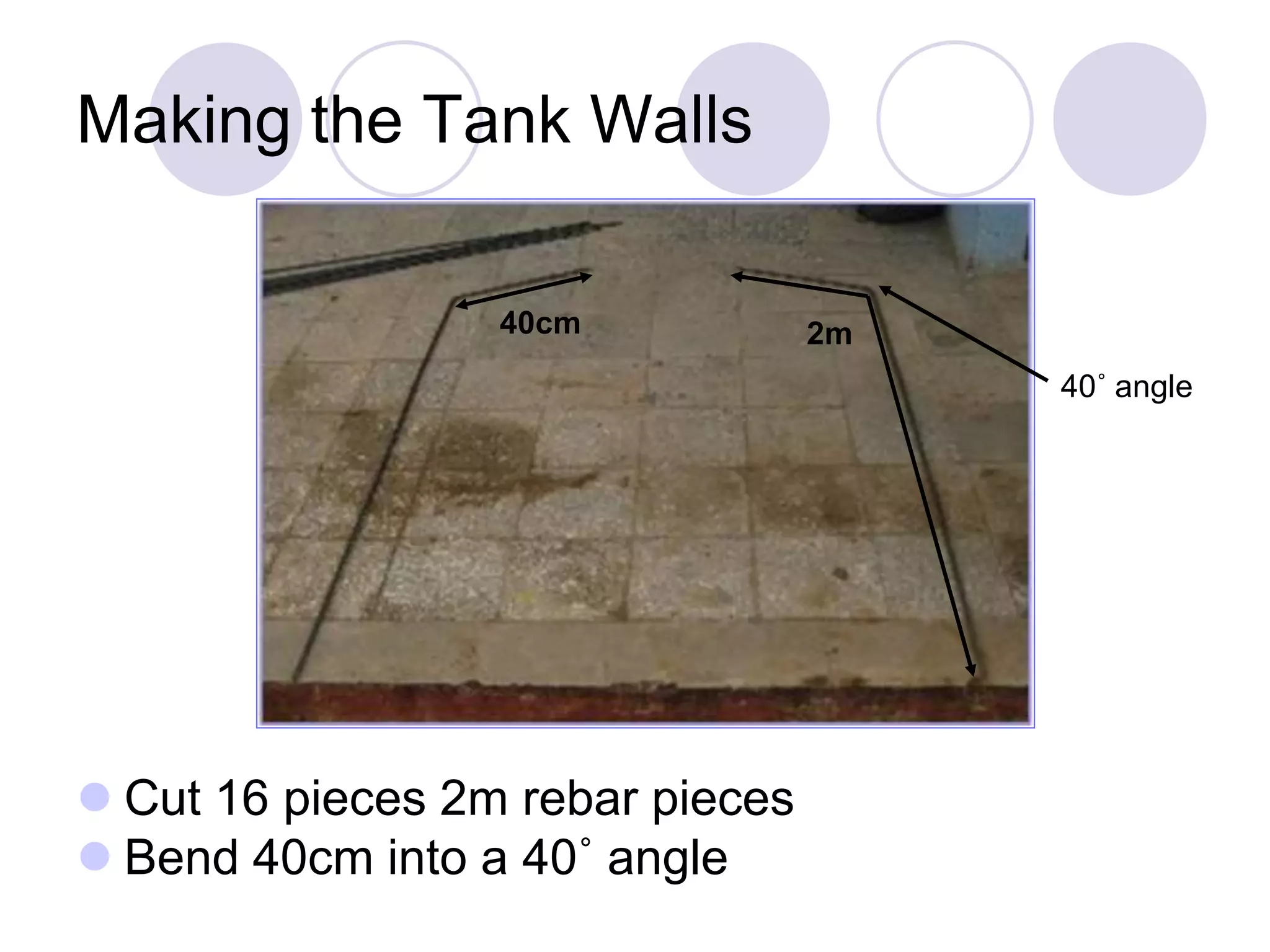
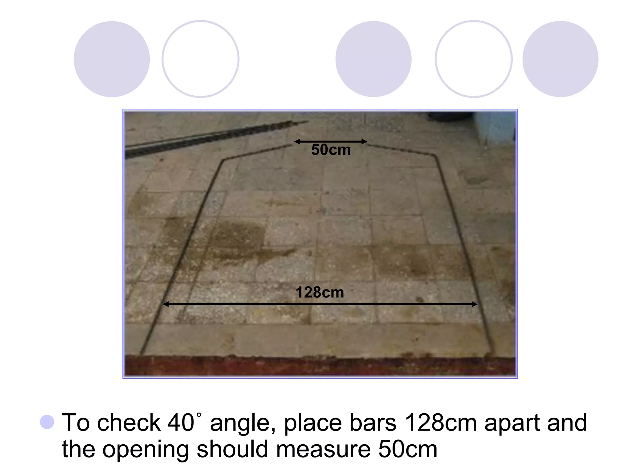
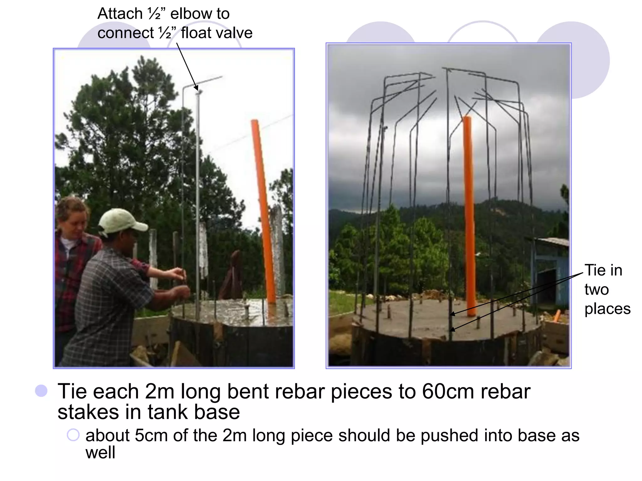
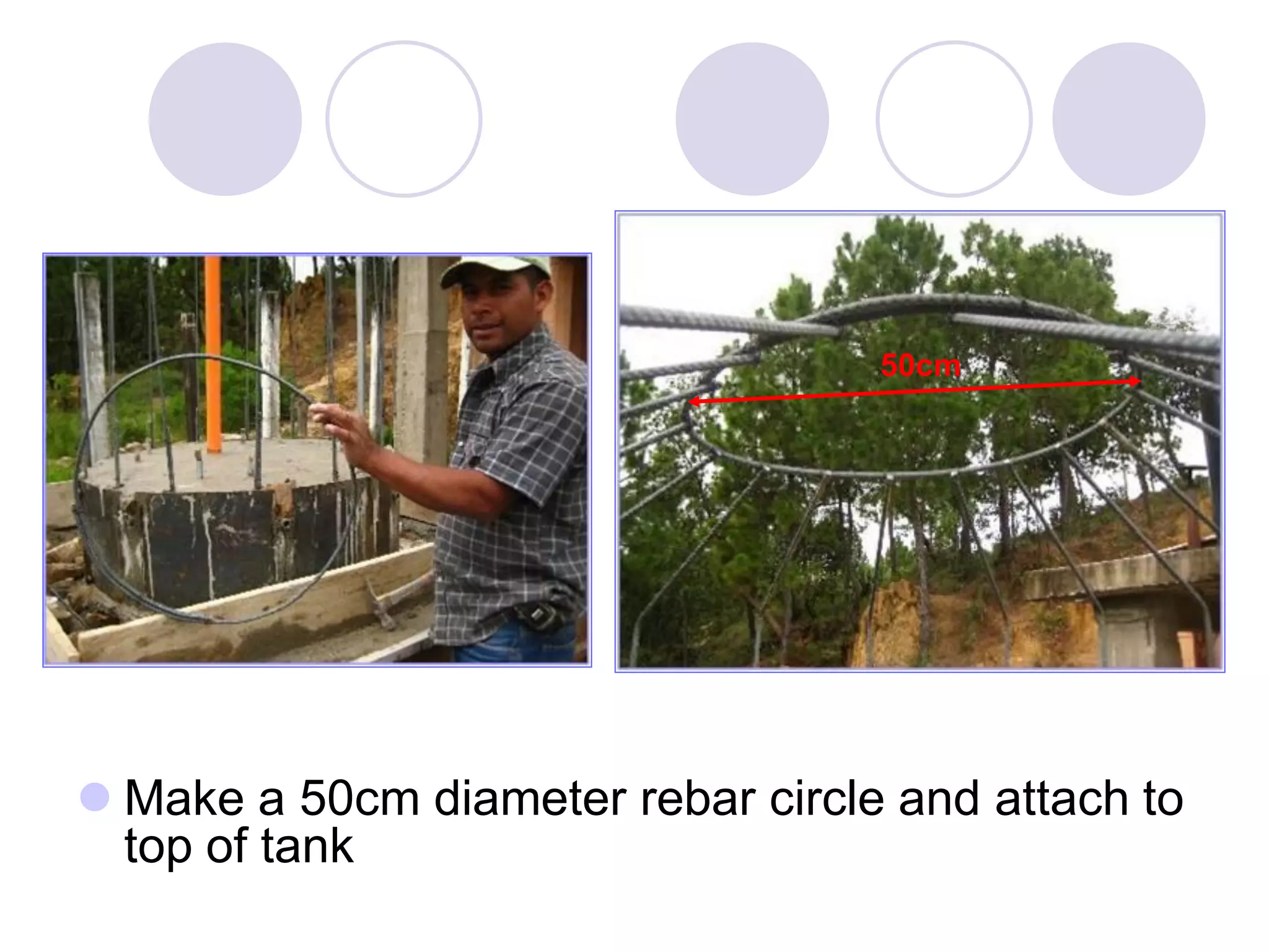
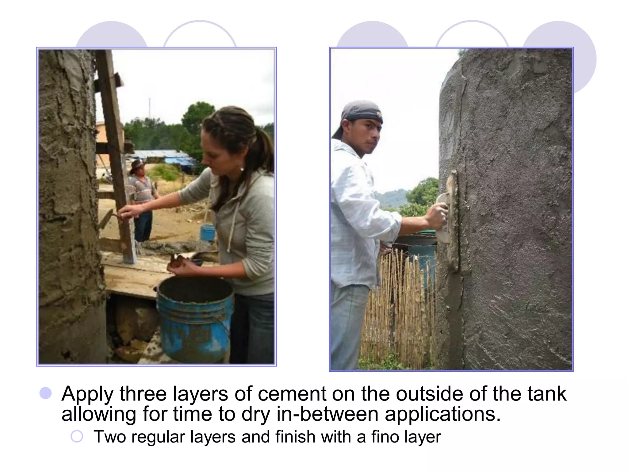
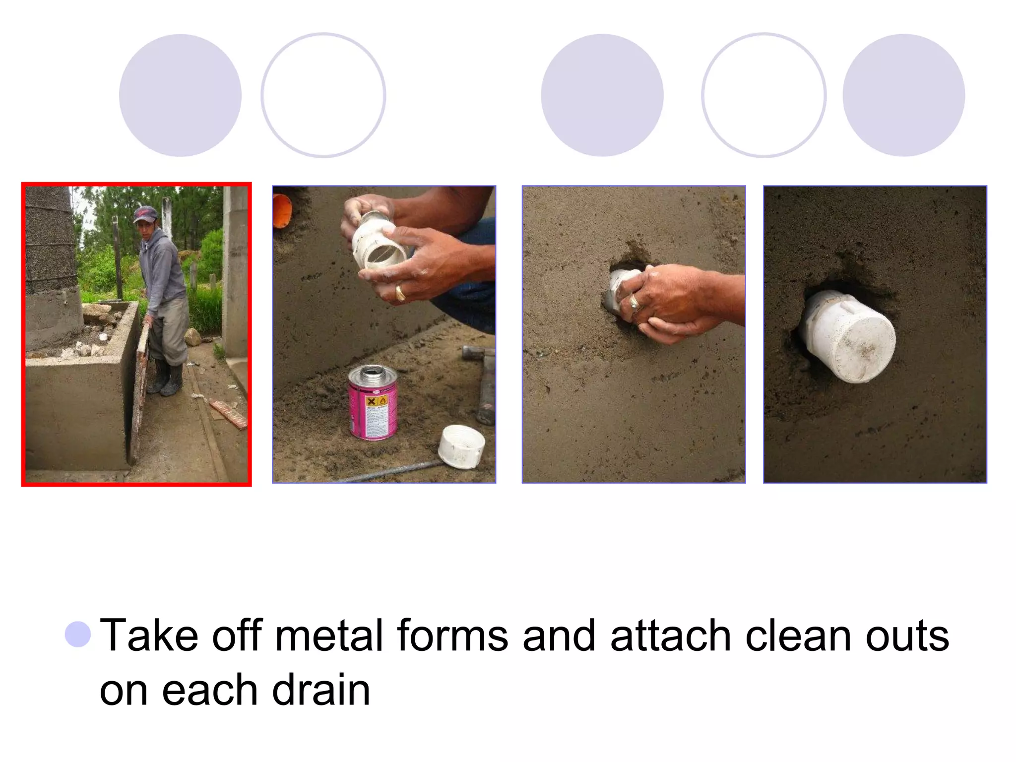
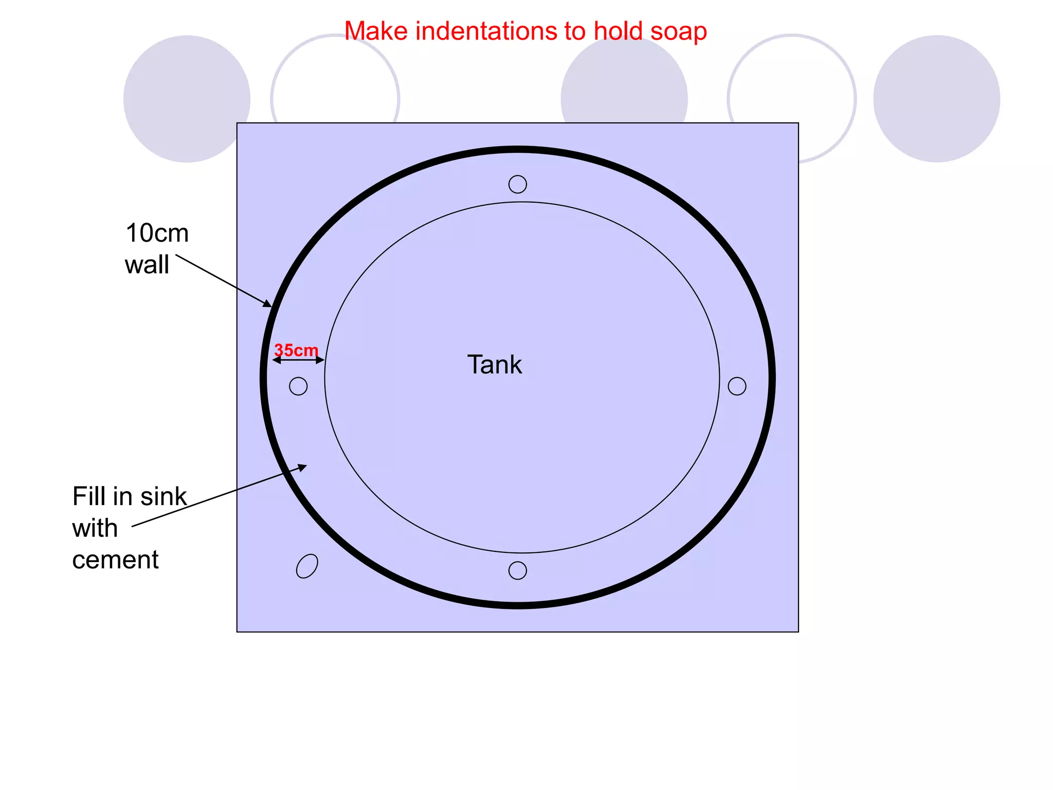
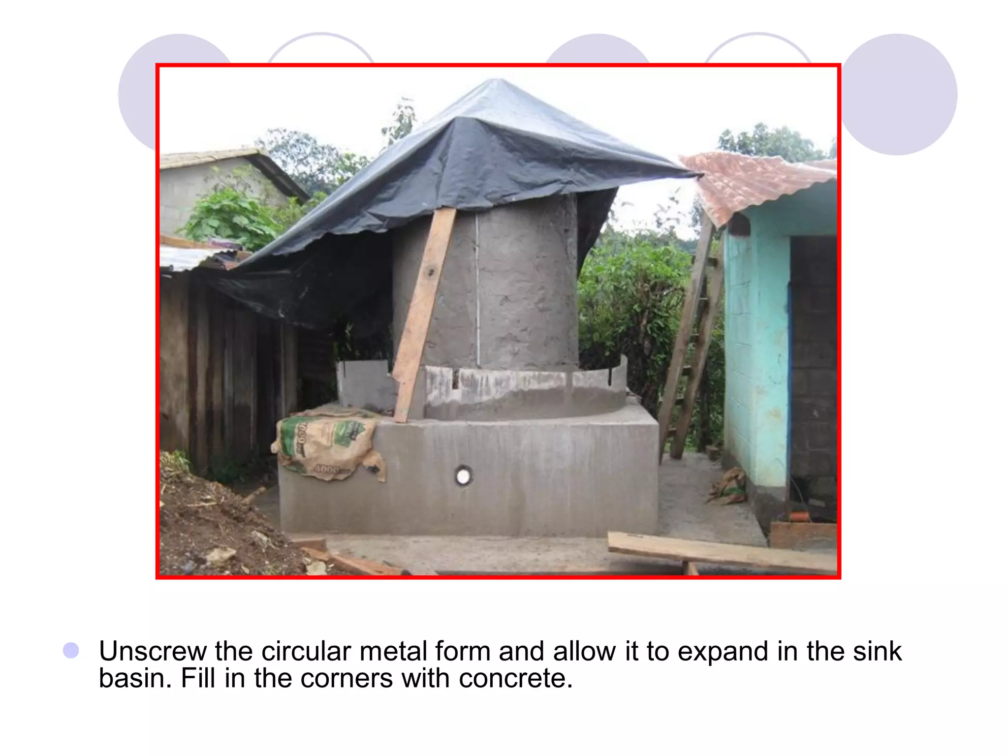
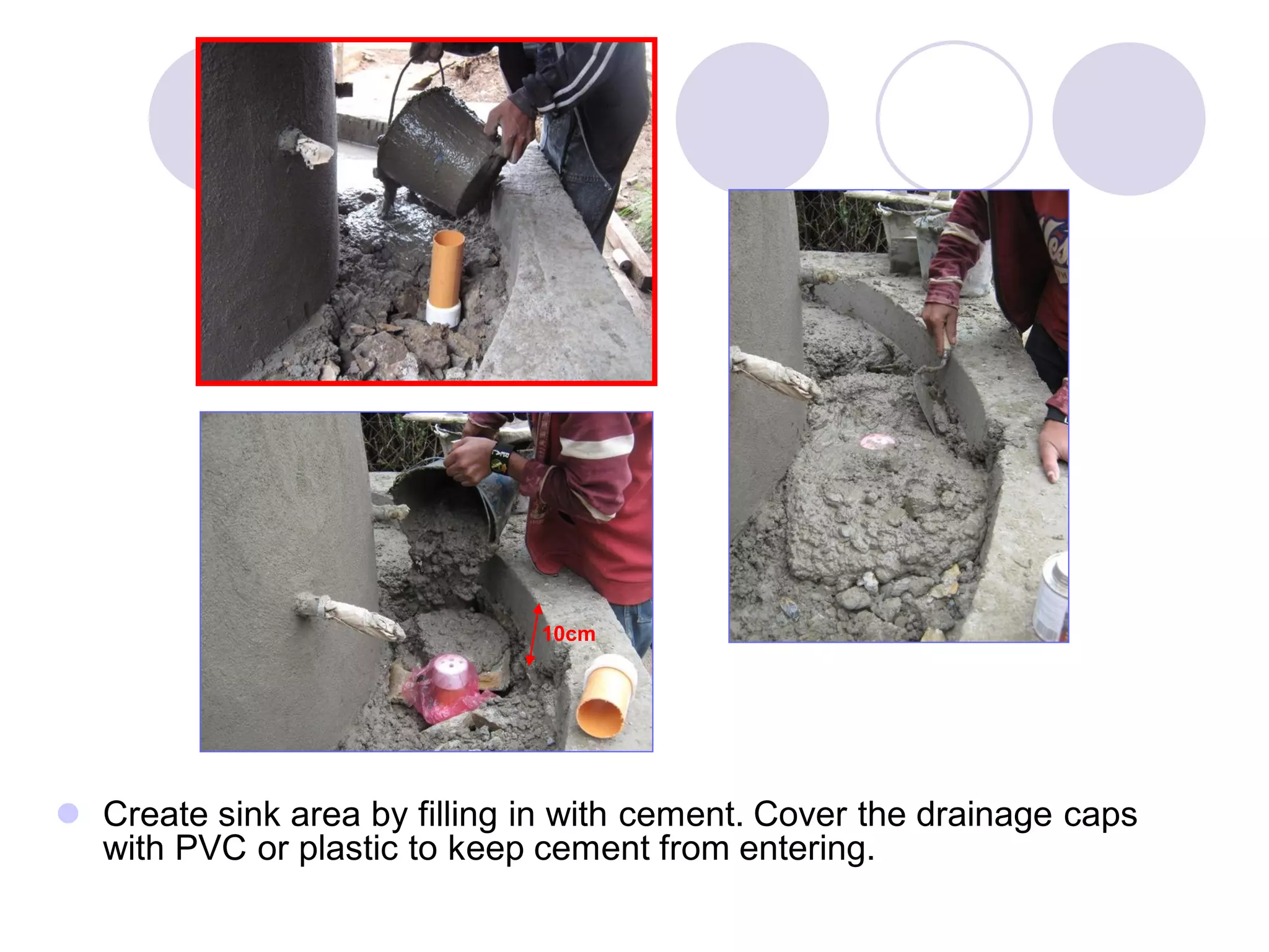
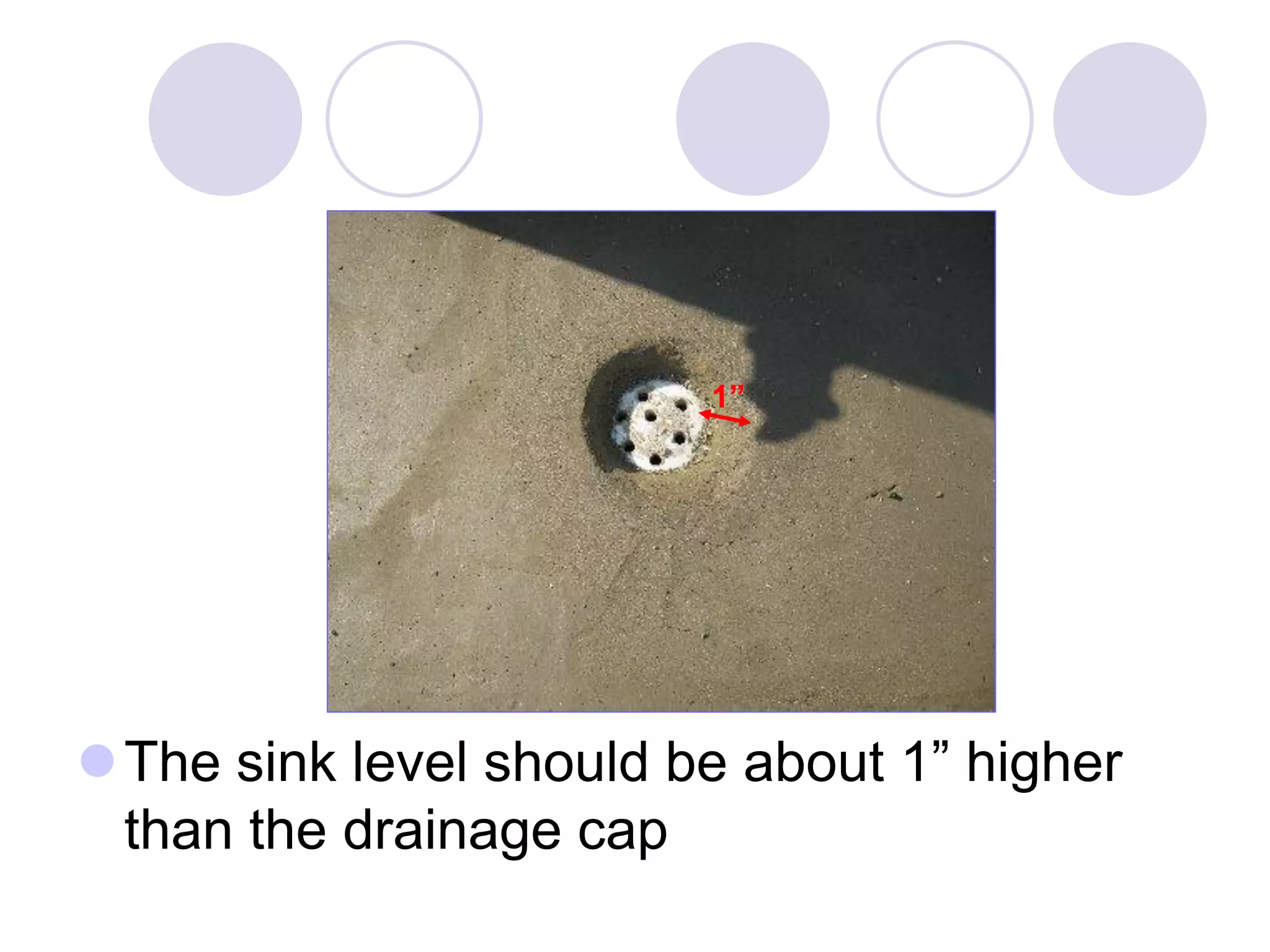
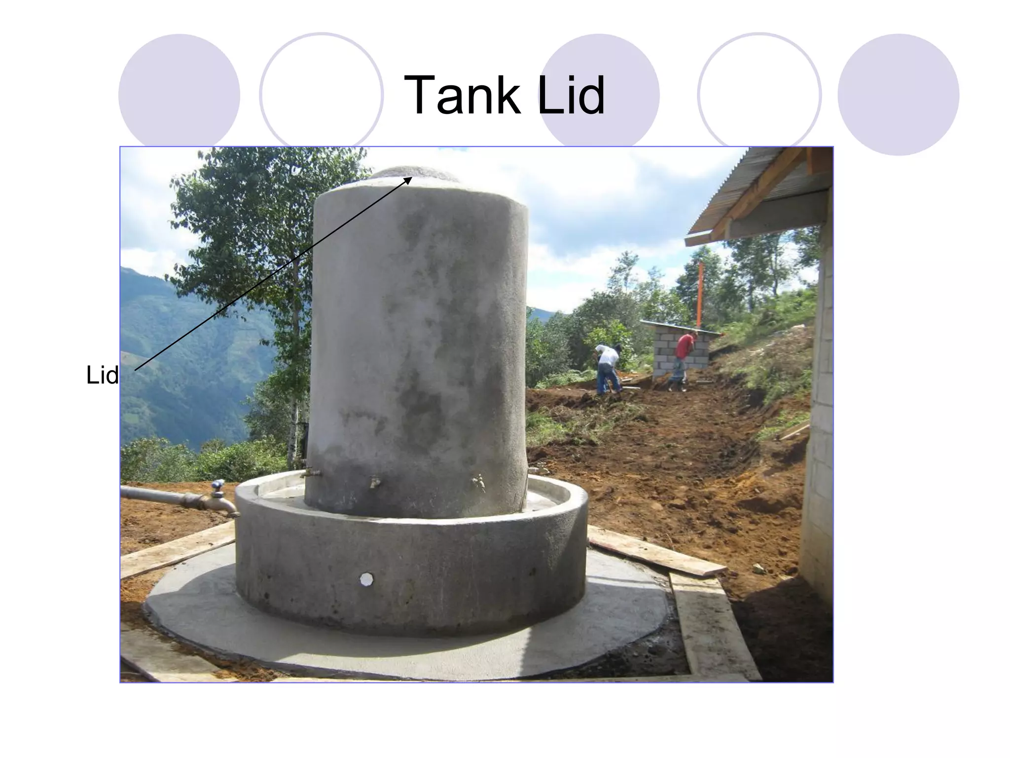
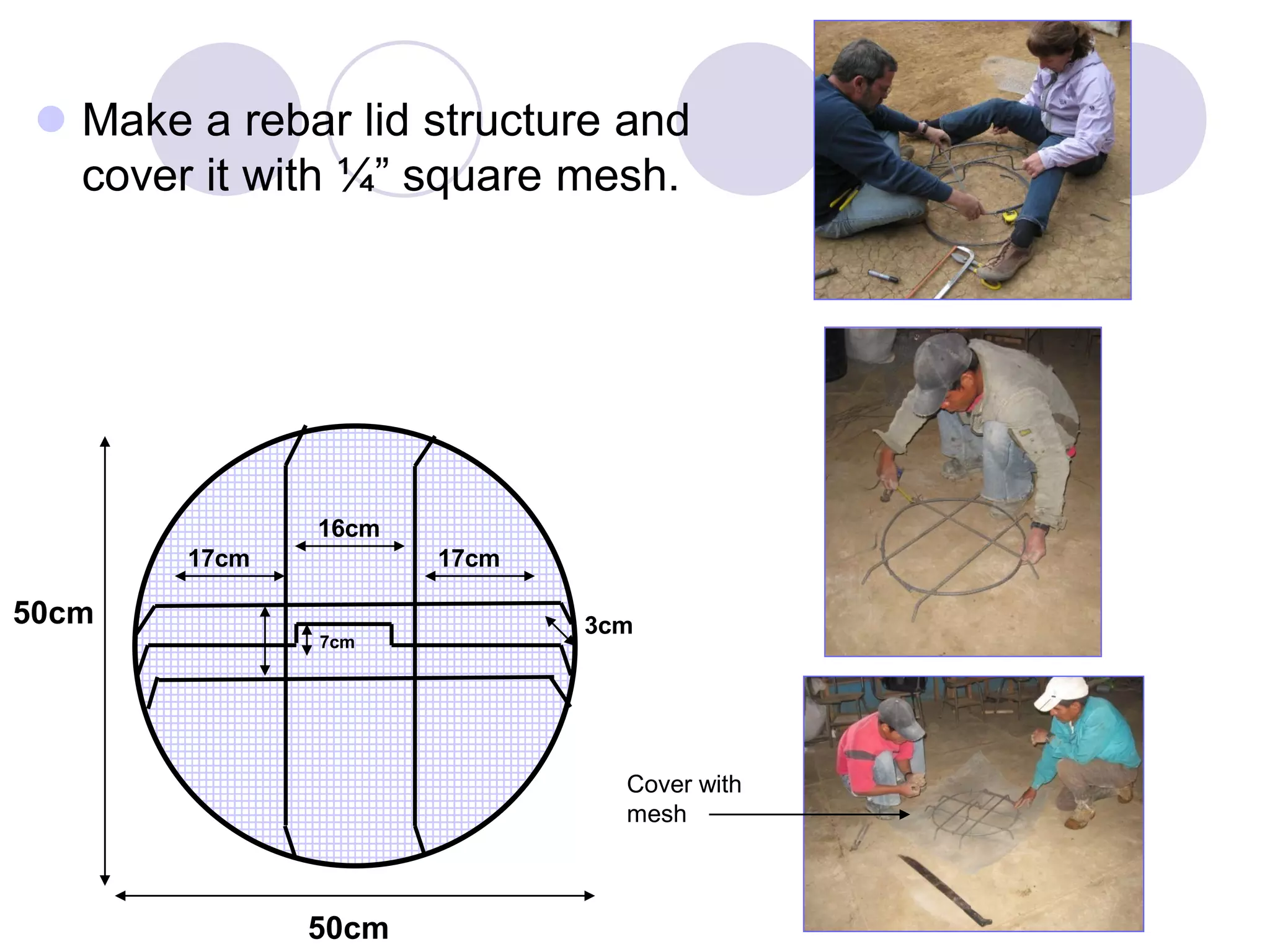
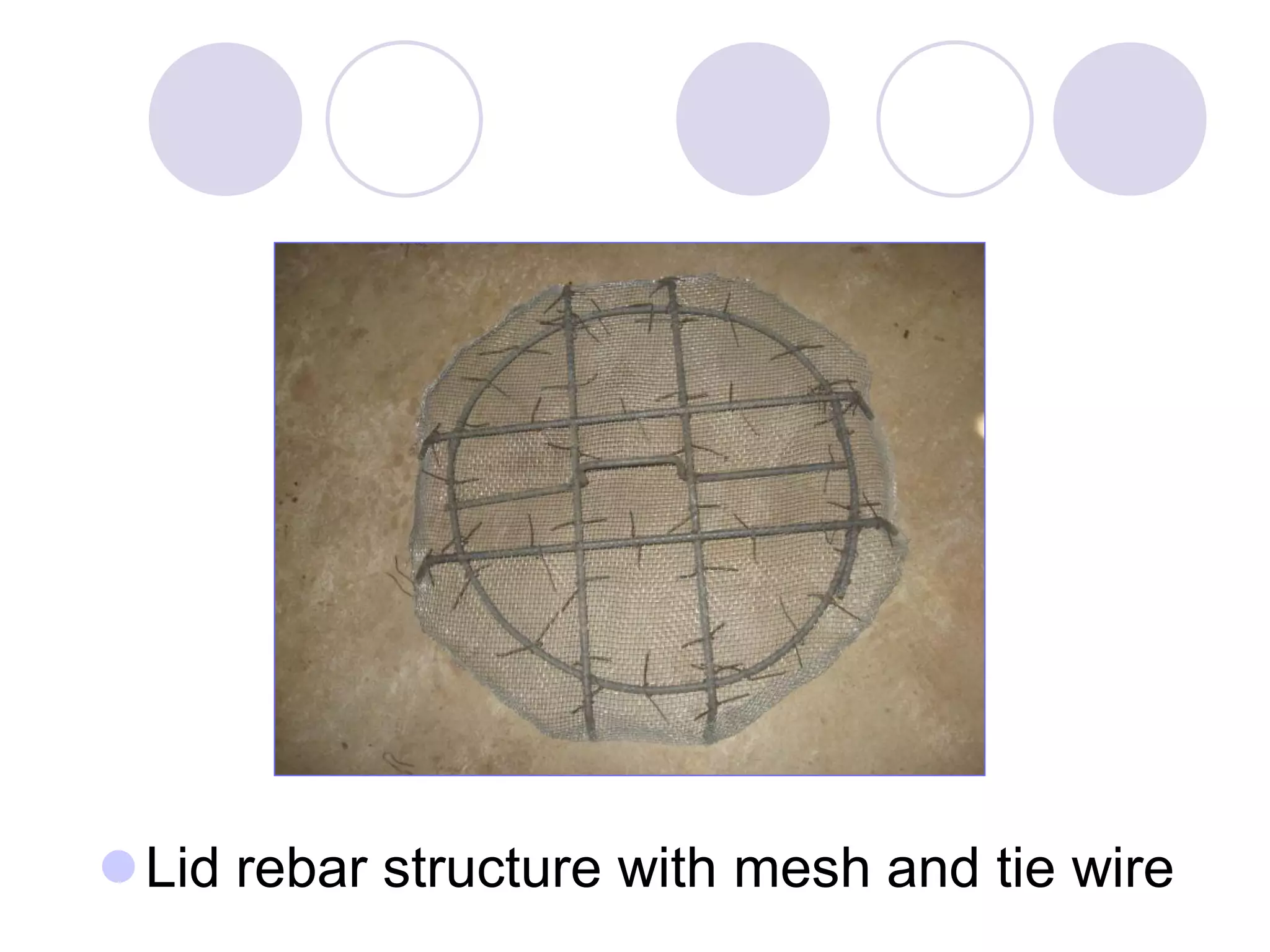
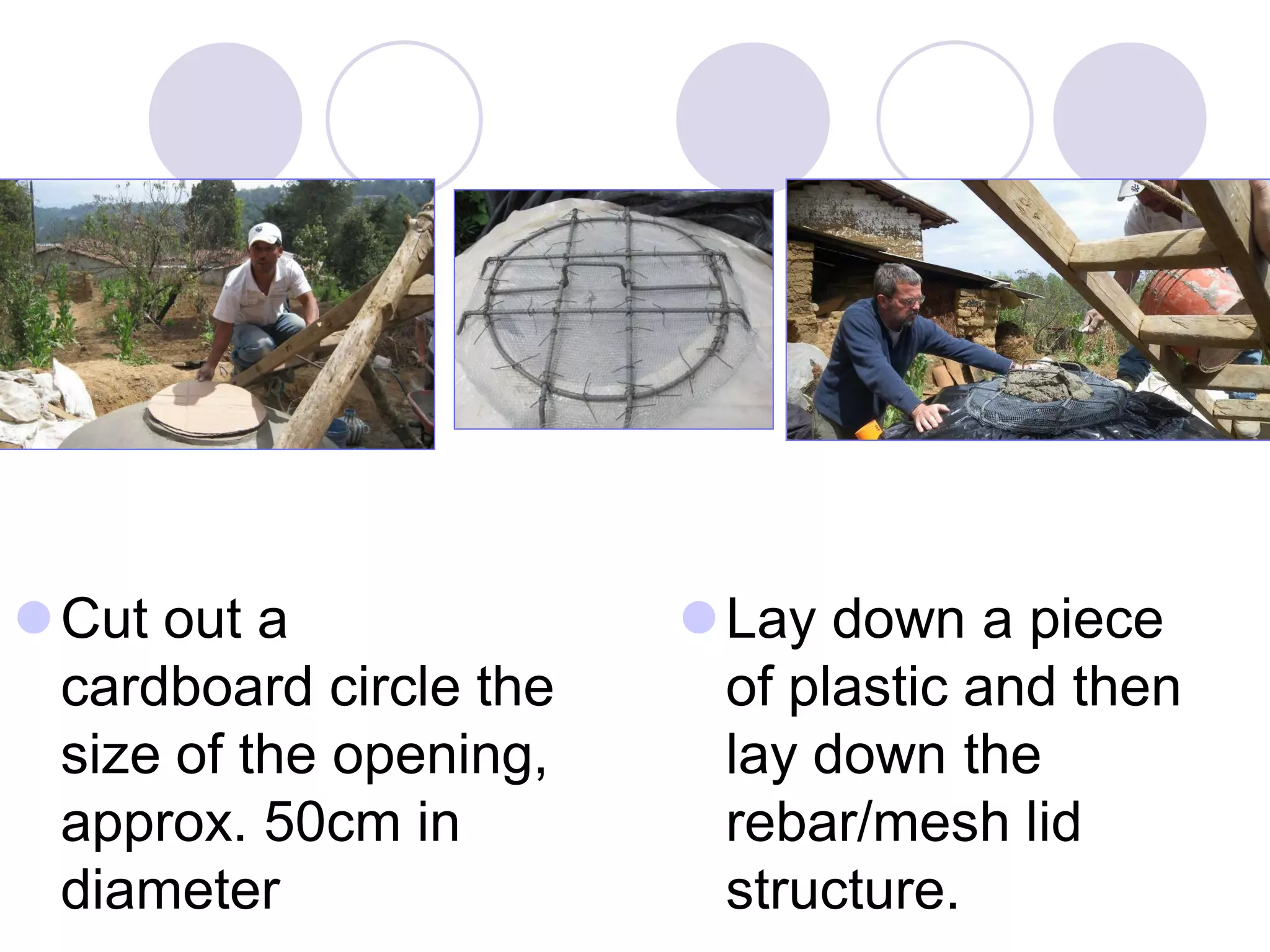
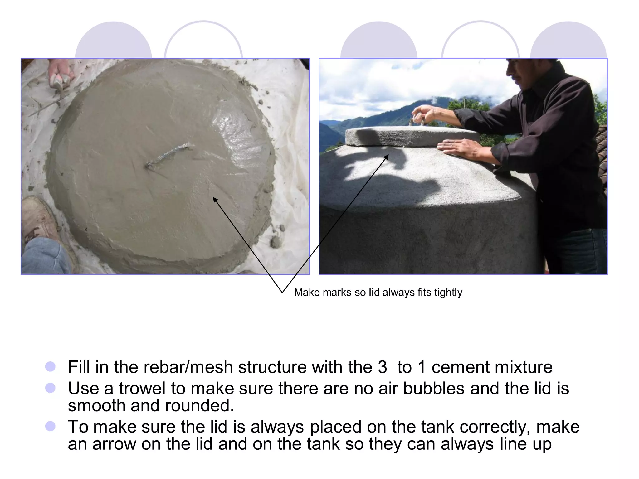
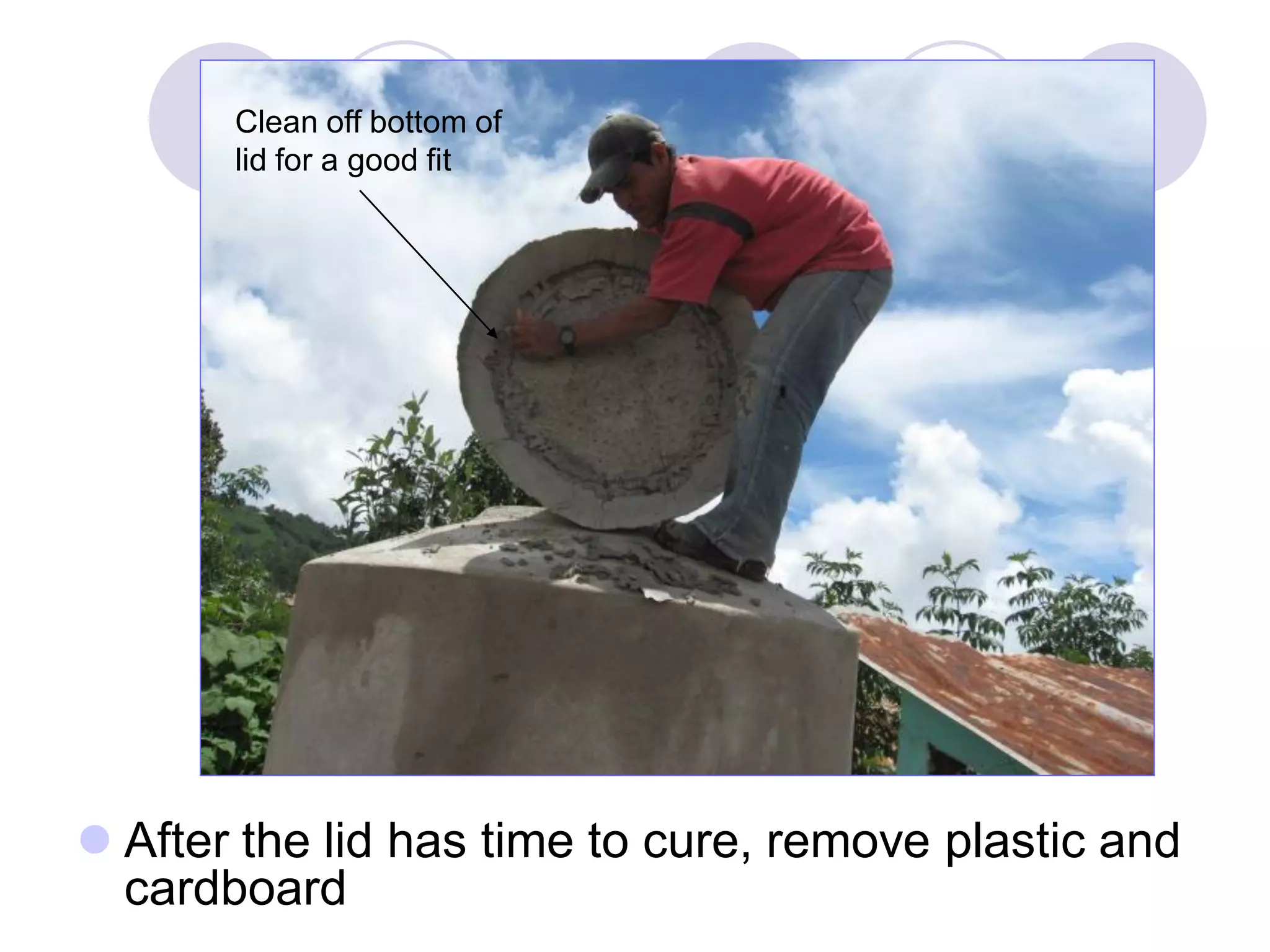
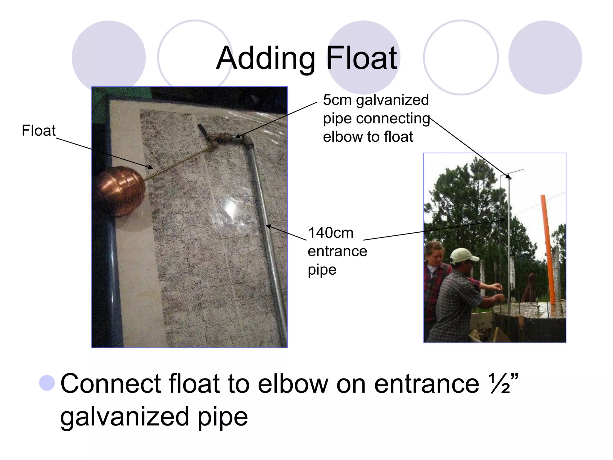
How to Make an 8-Faucet Ferro-
Cement Hand Washing Station
Created by Jackie Powell
Agua para la Salud
Nebaj, Guatemala
June 2010
What is Ferrocement?
 A composite
material--in this case
using cement, rebar,
and square mesh for
enforcement
 Once the frame of a
structure is created
using rebar and
mesh, cement is
applied
Rebar &
mesh
structure
Applying
cement
Cement vs. Concrete
Our definitions of cement and concrete:
Cement= sand + powdered cement + water
Concrete= gravel + sand + powdered cement +
water
 We suggest using 4000 PSI powdered
cement
Cement Mixture Proportions
Regular= 2 sand x 1 powdered cement
using a 23 caliber sifter or ½” wire mesh
Mix in a location with no rocks
Fino= 2 sand x 1 powdered cement
Using an extremely fine sifter
Mix in wheelbarrow
Liso= pure powdered cement + water
Mix in wheelbarrow
Concrete Mixture Proportions
 Concrete mixture varies
depending on size of
gravel in your location
 If ¾” grade gravel is
available the mixture
should be: 2.5 gravel x 2
sand x 1 powered
cement
 Otherwise, it is a good
idea to ask nearby
concrete company for
the best mixture for the
area
 In Guatemala we use a
2x1x1 mixture
Steps
Placement &
Leveling
Making the Base
Laying Pipe
Making the Wall
Placing Drainage
Tubes & Clean
Outs
Steps Continued
 Finishing the Wall
 Making the 2000L
Tank
 Making Tank Walls
Cementing the Tank
 Finishing Touches
Four Clean Outs
35cm Sink Basin
Tank Lid
Adding Float
Placement & Leveling
 Before construction, think of an ideal location for the hand washing
station. If possible place in a location near bathrooms and kitchen
and not in a location that will be needed for the construction of future
classrooms, football fields, etc.
 Level an area of at least 4x4 meters and determine an area to mix
concrete and cement
4x4m
Making the Base
Base
 Make a level wooden form for base measuring
3.2 x 3.2 meters and 15cm deep. Use a line
level to level the wooden form
3.2x3.2 meters
15cm deep
15cm deep
63cm
3m
3m
Make rebar base structure 3 x 3 meters
 To create: cut 12- 3m rebar pieces & 20 -65cm rebar pieces (creating
squares measuring 25 x 25 cm). Tie each junction with tie wire.
25cm
25cm
Laying Pipe
Drainage 2” PVC- enters
seepage pit or septic tank
Inflow ½” galvanized pipe-
connects to water source
1.2m
1.3m
 Make a one-layer, 60cm thick layer of rock with 10 cm
space between rock and wooden board frame.
60cm
 Overflow & Clean Out 2” PVC- enters tank,
placed above rock layer
1.2m
3.2m base
3.2mbase
2.2m wall
2.2mwall
150cm
150cm
Overflow
& Clean Out
165cm
75cm
Drainage
160cm
95cm
Aerial
View of
Pipe
Placement
in
Relation
to the
Base
Entrance
½”
galvanized
pipe
35cm between tank
and wall
Place the rebar frame on top of rock layer.
Fill in 60cm rock frame with concrete.
Making the Wall
WALL
CLEAN OUTS
Make rebar wall structure with 4 rings of #cm
diameter, spaced 15cm apart bound with #
verticals measuring 56cm spaced 27cm
27cm
27cm27cm 27cm27cm 27cm27cm 27cm
15cm15cm15cm
Tie each
junction
with tie
wire.
40cm
5cm
Put together the larger metal wall
form.
Place the rebar structure inside of the outer
wall and adjust to ensure a 5cm space all
around.
 Place the wall form and rebar on top of the
foundation.
 Fill with stones.
Placing Drainage Tubes & Clean Outs
Fill in with large rocks leaving 20cm from
the rock to top of wooden form
20cm
20cm
Cross should be placed in center of frame
Attach four pieces of 75cm long 2” PVC
tube from each opening of the cross
75cm
 Then attach a T connection 25cm from wooden form
 Add another piece of PVC tube until it reaches the end of
the form
 Attach drainage cap to T and make sure it is level with
top of wooden form should be 15cm from the top of
wooden form
Drainage cap is made
by drilling 5/16” holes
in a 2” PVC cap
25cm
15cm
 One drain should be connected to drainage tube using a
cross connection
 This drain should be angled slightly lower than other
drains (17cm from top of wooden form) allowing for gray
water to flow downhill into drainage tube
Drainage tube
connecting to
seepage pit or
absorption tank
Four clean outs at
each end of drain
Clean outs can be
placed before or
after pouring
concrete. SEE
SLIDES # 59&60
Glue all tubes together!
Angled slightly
downhill
Aerial view of wall form
Inner Form
Rebar
frame
Outer
Form
10 cm
 Put together the smaller metal form for the
inner side of the wall and place on top of
stones.
 Fill in 10cm space with concrete and smooth
top
Making the 2000L Tank
Tank
Faucets
Screw together circular metal form
Measurements for circular metal form
15cm
5cm
40cm
40cm
40cm
40cm
40cm
Distances
between faucet
slots
 Place circular metal form 35cm from inner wall of
metal form, making sure it’s level.
35cm
Level!
 Make two rebar rings to fit into circular metal form
 Rings should have a diameter of 128cm, using a 4.35m
piece of rebar allowing for 35cm of overlap should work
nicely
 Cut 16 pieces of 60cm long rebar
 Tie 16 pieces onto rings 25cm apart
60cm rebar pieces tied to
rebar rings
25cm
apart
Fill in with rock and concrete to top of
circular metal form
Place ½” galvanized steel
faucet pipes in 8 openings at
a slight angle
15cm
20cm
 Fill in circular metal form with concrete and level
off with wooden board leaving the center a bit
lower than the edges
Level
with
board
 Add a 140cm ½” galvanized pipe to existing pipe
Making the Tank Walls
 Cut 16 pieces 2m rebar pieces
 Bend 40cm into a 40˚ angle
40˚ angle
40cm 2m
 To check 40˚ angle, place bars 128cm apart and
the opening should measure 50cm
128cm
50cm
 Tie each 2m long bent rebar pieces to 60cm rebar
stakes in tank base
 about 5cm of the 2m long piece should be pushed into base as
well
Tie in
two
places
Attach ½” elbow to
connect ½” float valve
 Make a 50cm diameter rebar circle and attach to
top of tank
50cm
Make 6 rebar rings with diameters of
128cm each and tie them 25cm apart
Rebar
rings
placed
25cm
apart
Also, add one rebar ring to top of tank
Adding
rebar
ring to
top
 Make several 100 -10cm long U-shaped wire
pieces
 Using U-shaped pieces to secure, place one layer of ¼”
square mesh on rebar structure and tie securely with tie
wire.
Inflow ½” galvanized pipe needs to be
have an extra layer of mesh tied around it
from the inside of the tank
Cementing the Tank
 Add first layer 2x1 cement mixture from inside
tank and allow to dry overnight
Pay special
attention when
covering this
pipe with cement
Add layer of 2x1
cement on top of
tank the next day
 Apply three layers of cement on the outside of the tank
allowing for time to dry in-between applications.
 Two regular layers and finish with a fino layer
Finish with a fino layer
 Apply four more layers of cement inside the tank.
Two regular, one fino, and one liso
Finishing Touches:
Four Clean Outs
Clean Outs
2” male or female threaded adaptors with
appropriate cap can be used for clean outs
Female with male cap Male with female cap
Take off metal forms and attach clean outs
on each drain
35cm Sink Basin
Sink Basin
10cm
wall
Tank
Fill in sink
with
cement
Make indentations to hold soap
35cm
 Unscrew the circular metal form and allow it to expand in the sink
basin. Fill in the corners with concrete.
 Create sink area by filling in with cement. Cover the drainage caps
with PVC or plastic to keep cement from entering.
10cm
The sink level should be about 1” higher
than the drainage cap
1”
Tank Lid
Lid
 Make a rebar lid structure and
cover it with ¼” square mesh.
50cm
16cm
17cm
50cm
17cm
7cm
3cm
Cover with
mesh
Lid rebar structure with mesh and tie wire
Cut out a
cardboard circle the
size of the opening,
approx. 50cm in
diameter
Lay down a piece
of plastic and then
lay down the
rebar/mesh lid
structure.
 Fill in the rebar/mesh structure with the 3 to 1 cement mixture
 Use a trowel to make sure there are no air bubbles and the lid is
smooth and rounded.
 To make sure the lid is always placed on the tank correctly, make
an arrow on the lid and on the tank so they can always line up
Make marks so lid always fits tightly
 After the lid has time to cure, remove plastic and
cardboard
Clean off bottom of
lid for a good fit
Adding Float
Connect float to elbow on entrance ½”
galvanized pipe
Float
140cm
entrance
pipe
5cm galvanized
pipe connecting
elbow to float

How to Make a Lavamanos-RoundBASE

  • 1.
    How to Makean 8-Faucet Ferro- Cement Hand Washing Station Created by Jackie Powell Agua para la Salud Nebaj, Guatemala June 2010
  • 2.
    What is Ferrocement? A composite material--in this case using cement, rebar, and square mesh for enforcement  Once the frame of a structure is created using rebar and mesh, cement is applied Rebar & mesh structure Applying cement
  • 3.
    Cement vs. Concrete Ourdefinitions of cement and concrete: Cement= sand + powdered cement + water Concrete= gravel + sand + powdered cement + water  We suggest using 4000 PSI powdered cement
  • 4.
    Cement Mixture Proportions Regular=2 sand x 1 powdered cement using a 23 caliber sifter or ½” wire mesh Mix in a location with no rocks Fino= 2 sand x 1 powdered cement Using an extremely fine sifter Mix in wheelbarrow Liso= pure powdered cement + water Mix in wheelbarrow
  • 5.
    Concrete Mixture Proportions Concrete mixture varies depending on size of gravel in your location  If ¾” grade gravel is available the mixture should be: 2.5 gravel x 2 sand x 1 powered cement  Otherwise, it is a good idea to ask nearby concrete company for the best mixture for the area  In Guatemala we use a 2x1x1 mixture
  • 6.
    Steps Placement & Leveling Making theBase Laying Pipe Making the Wall Placing Drainage Tubes & Clean Outs
  • 7.
    Steps Continued  Finishingthe Wall  Making the 2000L Tank  Making Tank Walls Cementing the Tank  Finishing Touches Four Clean Outs 35cm Sink Basin Tank Lid Adding Float
  • 8.
    Placement & Leveling Before construction, think of an ideal location for the hand washing station. If possible place in a location near bathrooms and kitchen and not in a location that will be needed for the construction of future classrooms, football fields, etc.  Level an area of at least 4x4 meters and determine an area to mix concrete and cement 4x4m
  • 9.
  • 10.
     Make alevel wooden form for base measuring 3.2 x 3.2 meters and 15cm deep. Use a line level to level the wooden form 3.2x3.2 meters 15cm deep 15cm deep
  • 11.
    63cm 3m 3m Make rebar basestructure 3 x 3 meters
  • 12.
     To create:cut 12- 3m rebar pieces & 20 -65cm rebar pieces (creating squares measuring 25 x 25 cm). Tie each junction with tie wire. 25cm 25cm
  • 13.
    Laying Pipe Drainage 2”PVC- enters seepage pit or septic tank Inflow ½” galvanized pipe- connects to water source 1.2m 1.3m
  • 14.
     Make aone-layer, 60cm thick layer of rock with 10 cm space between rock and wooden board frame. 60cm
  • 15.
     Overflow &Clean Out 2” PVC- enters tank, placed above rock layer 1.2m
  • 16.
    3.2m base 3.2mbase 2.2m wall 2.2mwall 150cm 150cm Overflow &Clean Out 165cm 75cm Drainage 160cm 95cm Aerial View of Pipe Placement in Relation to the Base Entrance ½” galvanized pipe 35cm between tank and wall
  • 17.
    Place the rebarframe on top of rock layer.
  • 18.
    Fill in 60cmrock frame with concrete.
  • 19.
  • 20.
    Make rebar wallstructure with 4 rings of #cm diameter, spaced 15cm apart bound with # verticals measuring 56cm spaced 27cm 27cm 27cm27cm 27cm27cm 27cm27cm 27cm 15cm15cm15cm Tie each junction with tie wire.
  • 21.
    40cm 5cm Put together thelarger metal wall form. Place the rebar structure inside of the outer wall and adjust to ensure a 5cm space all around.
  • 22.
     Place thewall form and rebar on top of the foundation.  Fill with stones.
  • 23.
    Placing Drainage Tubes& Clean Outs Fill in with large rocks leaving 20cm from the rock to top of wooden form 20cm 20cm
  • 24.
    Cross should beplaced in center of frame
  • 25.
    Attach four piecesof 75cm long 2” PVC tube from each opening of the cross 75cm
  • 26.
     Then attacha T connection 25cm from wooden form  Add another piece of PVC tube until it reaches the end of the form  Attach drainage cap to T and make sure it is level with top of wooden form should be 15cm from the top of wooden form Drainage cap is made by drilling 5/16” holes in a 2” PVC cap 25cm 15cm
  • 27.
     One drainshould be connected to drainage tube using a cross connection  This drain should be angled slightly lower than other drains (17cm from top of wooden form) allowing for gray water to flow downhill into drainage tube Drainage tube connecting to seepage pit or absorption tank
  • 28.
    Four clean outsat each end of drain Clean outs can be placed before or after pouring concrete. SEE SLIDES # 59&60
  • 29.
    Glue all tubestogether! Angled slightly downhill
  • 30.
    Aerial view ofwall form Inner Form Rebar frame Outer Form 10 cm
  • 31.
     Put togetherthe smaller metal form for the inner side of the wall and place on top of stones.  Fill in 10cm space with concrete and smooth top
  • 32.
    Making the 2000LTank Tank Faucets
  • 33.
  • 34.
    Measurements for circularmetal form 15cm 5cm 40cm 40cm 40cm 40cm 40cm Distances between faucet slots
  • 35.
     Place circularmetal form 35cm from inner wall of metal form, making sure it’s level. 35cm Level!
  • 36.
     Make tworebar rings to fit into circular metal form  Rings should have a diameter of 128cm, using a 4.35m piece of rebar allowing for 35cm of overlap should work nicely
  • 37.
     Cut 16pieces of 60cm long rebar  Tie 16 pieces onto rings 25cm apart 60cm rebar pieces tied to rebar rings 25cm apart
  • 38.
    Fill in withrock and concrete to top of circular metal form
  • 39.
    Place ½” galvanizedsteel faucet pipes in 8 openings at a slight angle 15cm 20cm
  • 40.
     Fill incircular metal form with concrete and level off with wooden board leaving the center a bit lower than the edges Level with board
  • 41.
     Add a140cm ½” galvanized pipe to existing pipe
  • 42.
    Making the TankWalls  Cut 16 pieces 2m rebar pieces  Bend 40cm into a 40˚ angle 40˚ angle 40cm 2m
  • 43.
     To check40˚ angle, place bars 128cm apart and the opening should measure 50cm 128cm 50cm
  • 44.
     Tie each2m long bent rebar pieces to 60cm rebar stakes in tank base  about 5cm of the 2m long piece should be pushed into base as well Tie in two places Attach ½” elbow to connect ½” float valve
  • 45.
     Make a50cm diameter rebar circle and attach to top of tank 50cm
  • 46.
    Make 6 rebarrings with diameters of 128cm each and tie them 25cm apart Rebar rings placed 25cm apart
  • 47.
    Also, add onerebar ring to top of tank Adding rebar ring to top
  • 48.
     Make several100 -10cm long U-shaped wire pieces
  • 49.
     Using U-shapedpieces to secure, place one layer of ¼” square mesh on rebar structure and tie securely with tie wire.
  • 50.
    Inflow ½” galvanizedpipe needs to be have an extra layer of mesh tied around it from the inside of the tank
  • 51.
    Cementing the Tank Add first layer 2x1 cement mixture from inside tank and allow to dry overnight Pay special attention when covering this pipe with cement
  • 52.
    Add layer of2x1 cement on top of tank the next day
  • 53.
     Apply threelayers of cement on the outside of the tank allowing for time to dry in-between applications.  Two regular layers and finish with a fino layer
  • 54.
    Finish with afino layer
  • 55.
     Apply fourmore layers of cement inside the tank. Two regular, one fino, and one liso
  • 56.
  • 57.
    2” male orfemale threaded adaptors with appropriate cap can be used for clean outs Female with male cap Male with female cap
  • 58.
    Take off metalforms and attach clean outs on each drain
  • 59.
  • 60.
    10cm wall Tank Fill in sink with cement Makeindentations to hold soap 35cm
  • 61.
     Unscrew thecircular metal form and allow it to expand in the sink basin. Fill in the corners with concrete.
  • 62.
     Create sinkarea by filling in with cement. Cover the drainage caps with PVC or plastic to keep cement from entering. 10cm
  • 63.
    The sink levelshould be about 1” higher than the drainage cap 1”
  • 64.
  • 65.
     Make arebar lid structure and cover it with ¼” square mesh. 50cm 16cm 17cm 50cm 17cm 7cm 3cm Cover with mesh
  • 66.
    Lid rebar structurewith mesh and tie wire
  • 67.
    Cut out a cardboardcircle the size of the opening, approx. 50cm in diameter Lay down a piece of plastic and then lay down the rebar/mesh lid structure.
  • 68.
     Fill inthe rebar/mesh structure with the 3 to 1 cement mixture  Use a trowel to make sure there are no air bubbles and the lid is smooth and rounded.  To make sure the lid is always placed on the tank correctly, make an arrow on the lid and on the tank so they can always line up Make marks so lid always fits tightly
  • 69.
     After thelid has time to cure, remove plastic and cardboard Clean off bottom of lid for a good fit
  • 70.
    Adding Float Connect floatto elbow on entrance ½” galvanized pipe Float 140cm entrance pipe 5cm galvanized pipe connecting elbow to float