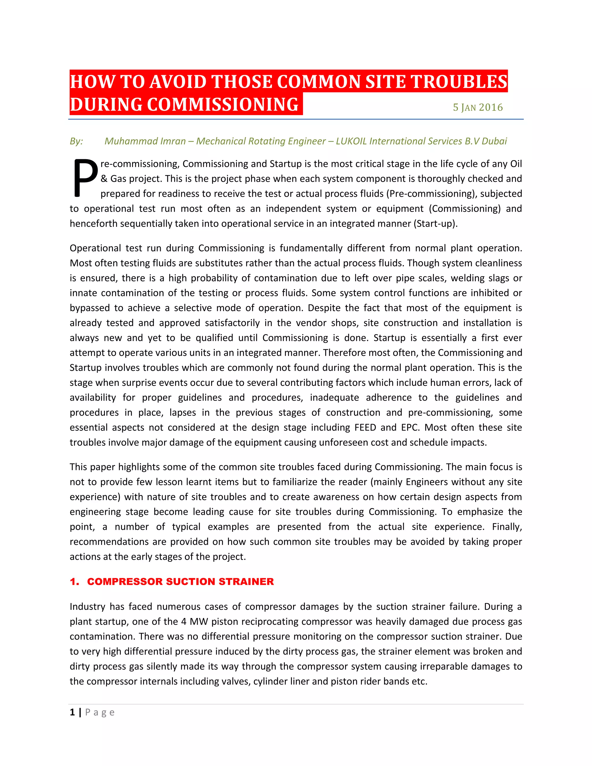
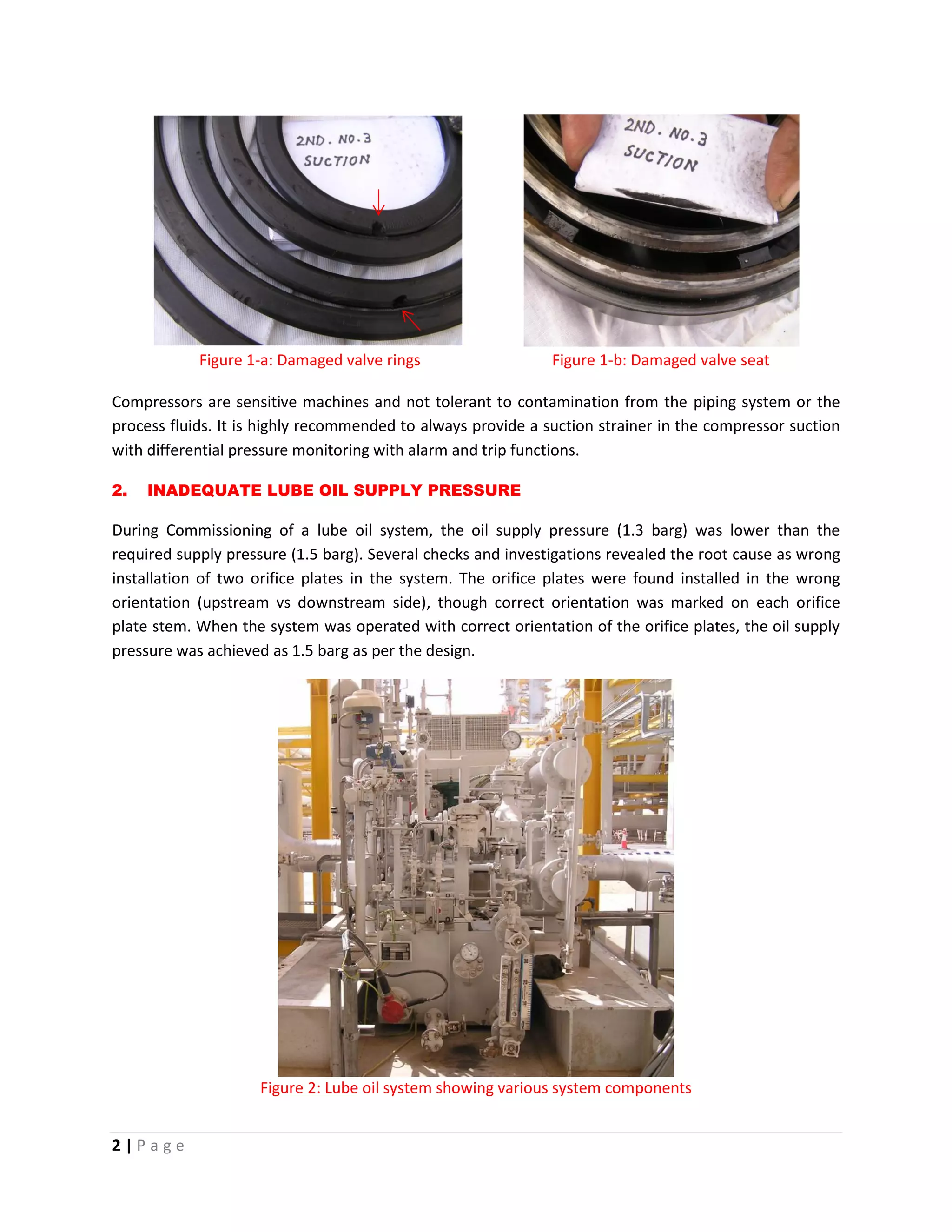
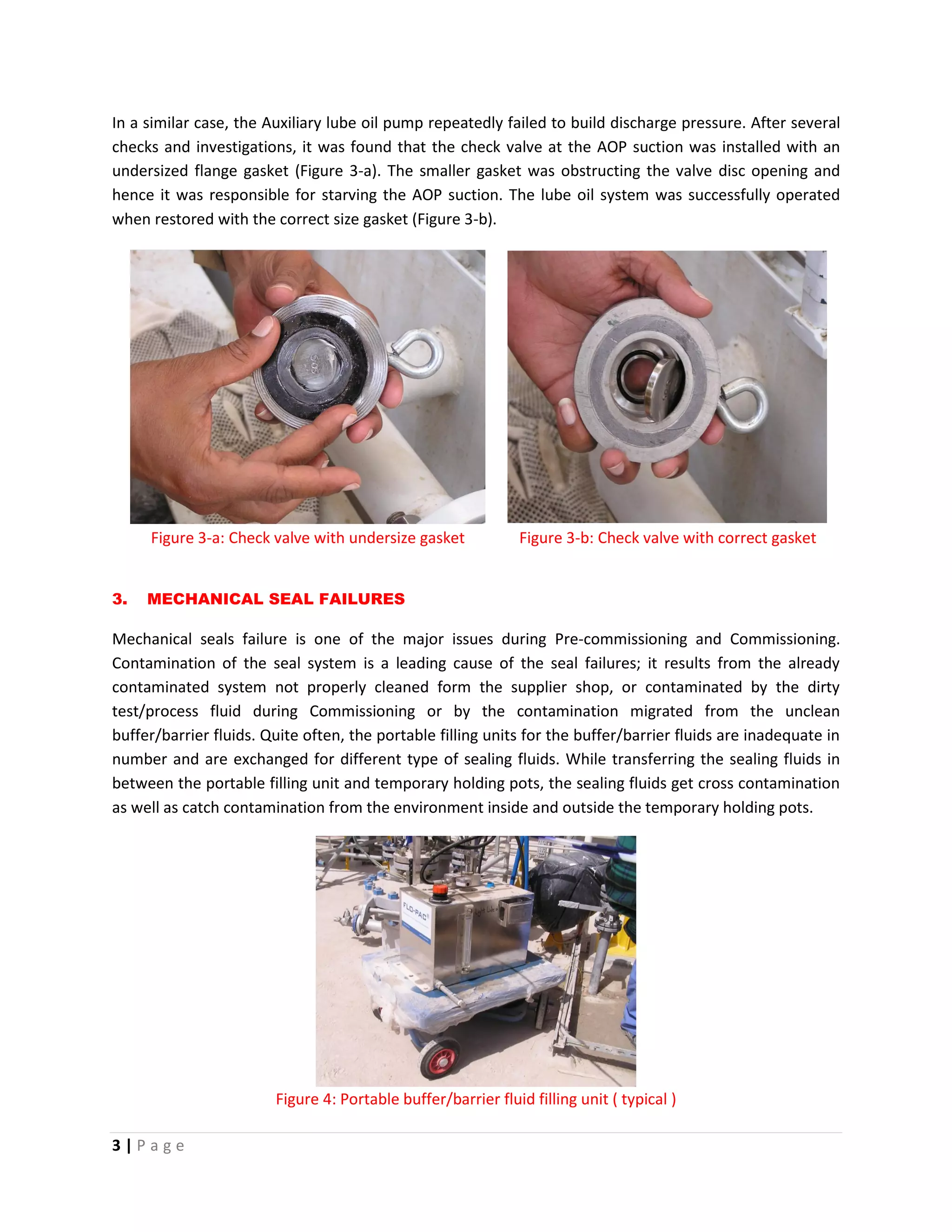
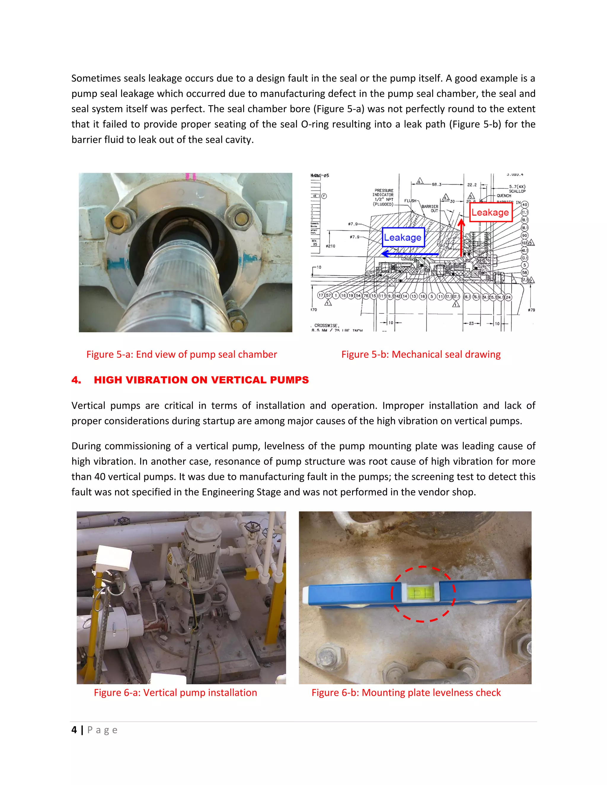
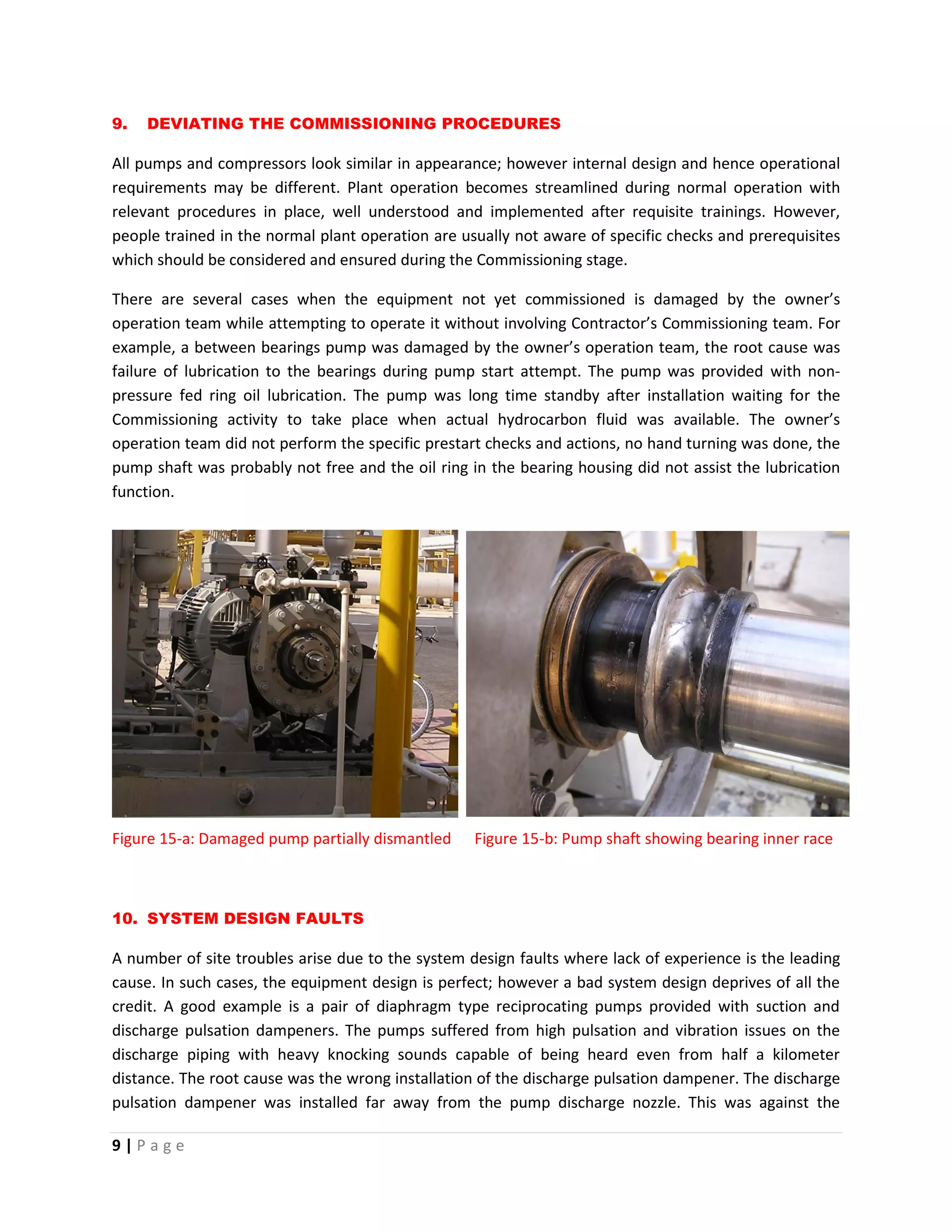
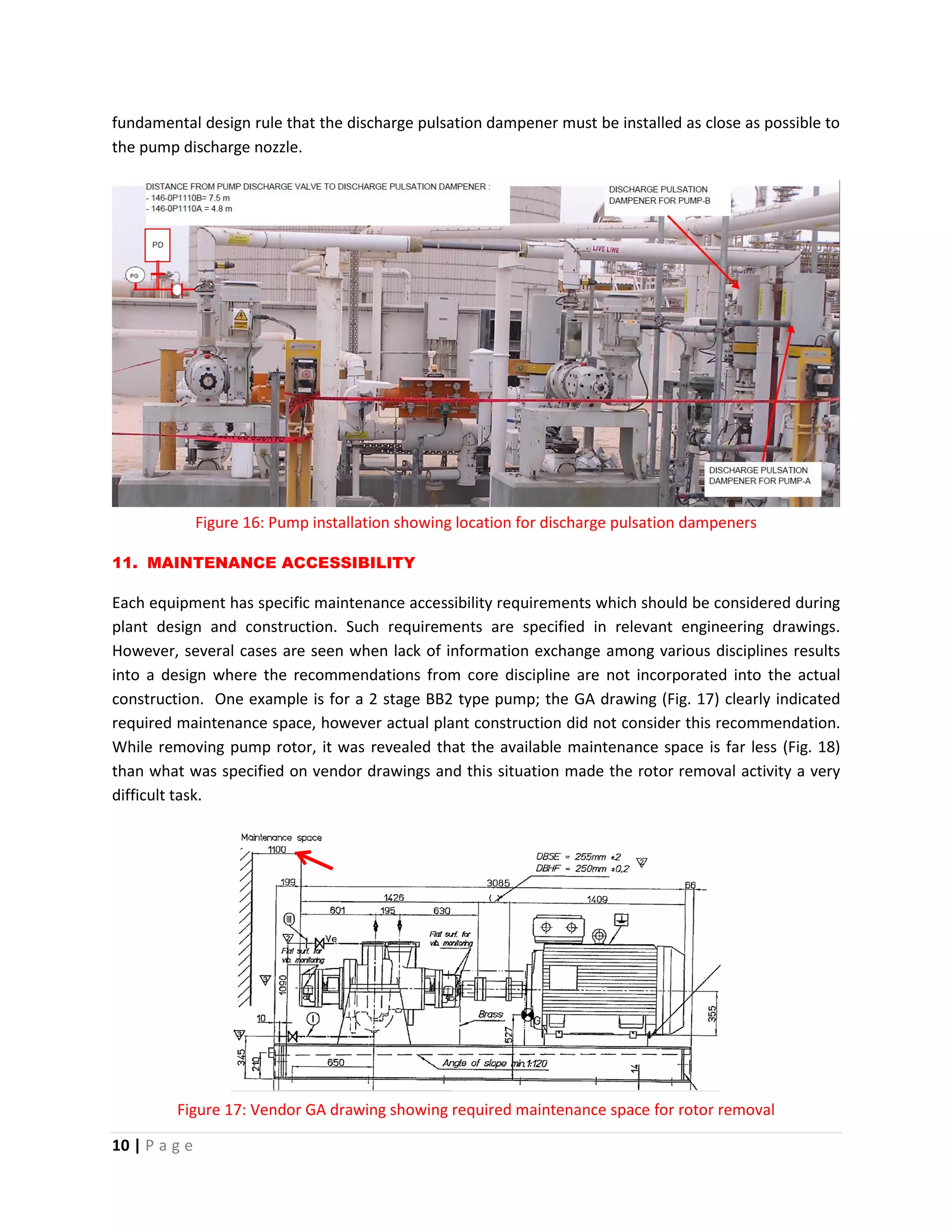
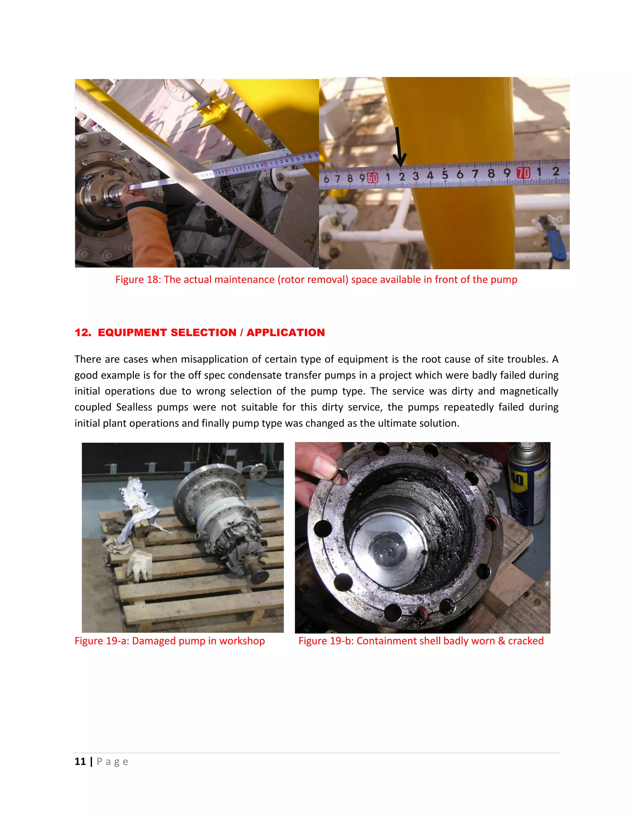
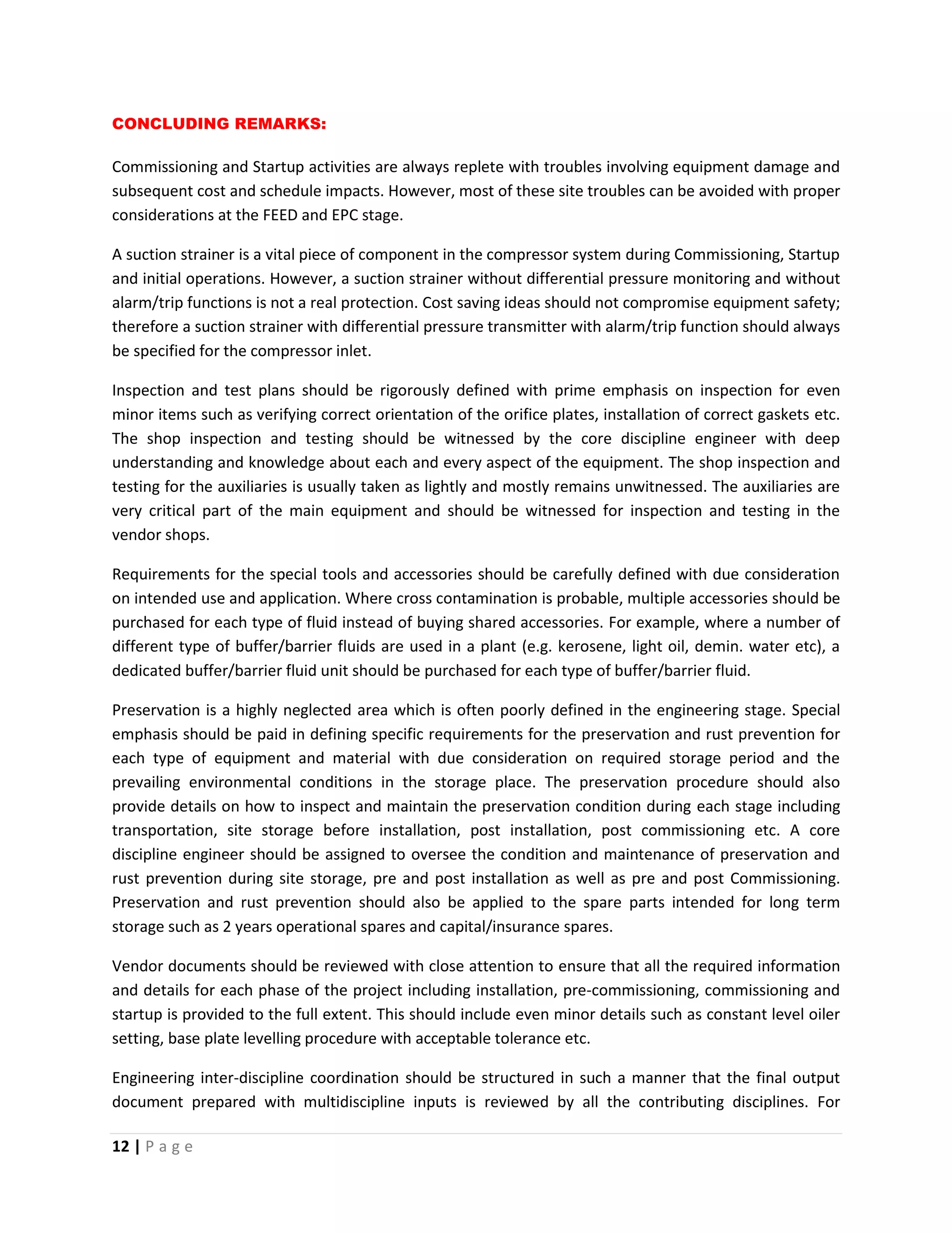
This document discusses common issues that arise during the commissioning stage of oil and gas projects. It begins by explaining that commissioning involves testing systems using substitute fluids and inhibited control functions, presenting new challenges compared to normal operation. Eight specific issues that often cause problems are then described in detail, including compressor damage from an unmonitored suction strainer, mechanical seal failures from contamination, high pump vibrations from improper installation, and safety hazards from a lack of safe design. The document emphasizes that addressing potential issues early in engineering and design can help avoid problems during commissioning.
This document discusses the design and operation of a lube oil rundown tank system used to provide lubrication to rotating equipment bearings during shutdown coast-down periods. It describes how the rundown tank is filled during startup and then provides gravity flow of lube oil to the bearings after shutdown when main and auxiliary lube oil pumps are lost. The rundown tank system includes components like a vent, level transmitter, filling valve, check valves, and overflow line that allow it to fill, circulate oil normally, and then feed oil to bearings during coast-down.
The document provides information on governing systems and common problems encountered. It discusses:
1. The key components of a governing system block diagram including pumps, valves, filters and overspeed testers.
2. Cleaning procedures and stroke check requirements for governing systems.
3. Parameters that should be followed including pressures, signals, valve lifts and temperatures.
4. Common governing problems like hunting, chattering, and sudden speed variations.
5. Case studies examining issues like improper servomotor assembly and a bent pilot valve spring causing load hunting.
This document provides troubleshooting guidance for common air compressor issues. It lists various problems air compressors may experience such as failing to operate, excessive noise, knocking, insufficient pressure, oil consumption issues and more. For each problem, it identifies potential causes and recommended solutions to resolve the issue. The document serves as an informative guide for technicians to diagnose and repair air compressor faults.
This document is a maintenance report for a condensate extraction pump from January 19-24, 2012. It details the disassembly, inspection, repair, and reassembly of the pump. Key activities included replacing worn bearing bushes and sleeves, measuring clearances, and commissioning the pump after reassembly. The report provides technical specifications and ensures proper documentation of the maintenance work.
For all the Gas Turbine lovers, the following presentation is aimed to cover the Major Inspection of the Gas Turbine (GE, Fr-9E). It is weaved with all of the major activities involved in MI, tools and tactics with addition of the reference values. Each activity is described with aid of pictures for detailed understanding.
Charles R. Rutan is a senior engineering advisor for Lyondell/Equistar Chemicals in Alvin, Texas. He has expertise in rotating equipment, hot tapping, and special engineering problems. This document discusses turbine overspeed trip protection. It describes the standards and designs for overspeed protection systems on steam turbines. It addresses the potential issues if an overspeed trip fails, like equipment damage or injury. It also discusses the factors that determine how fast a turbine can overspeed after a load loss, such as the rotor's time constant and any stored energy between the turbine and steam supply. Redundant and fast-acting overspeed systems are needed to safely shut down the turbine in the event of a load loss.
In modern power plants, extensive protections and interlocks are provided to isolate faulty equipment without causing further damage and allow reserve equipment to start up automatically. Protections detect abnormal parameters and trip equipment to prevent major damage. Interlocks make equipment states dependent to prevent incorrect operation. Protections include tripping the turbine for issues like high/low steam pressure, temperature, exhaust hood temperature, axial shift, differential expansion, eccentricity, pump failures, and low lubricating oil pressure.
Mechanical seals are key components in centrifugal pumps that prevent fluid from leaking out of the pump casing. They consist of two faces, one stationary and one rotating, located between the impeller and rear casing. Pumps in harsh environments require more abrasion-resistant seals than regular pumps. Mechanical seals reduce leakage compared to gland packings, saving power. Proper flushing plans are needed to lubricate, cool, and clean the seal while removing particles to minimize abrasion and extend seal life. Common operational and maintenance errors that reduce seal life include dry running, suction choking, foreign materials, improper flushing plans, misalignment, stuffing box issues, and failed bearings.
This document discusses mechanical seals which are used to prevent leakage in pumps and other equipment. It describes the need for seals to minimize leakage and prevent toxic fluids from escaping. Both static seals, used between non-moving parts, and dynamic seals, used between moving parts, are covered. Common static seals include gaskets and O-rings, while dynamic seals include gland packings and mechanical contact seals. The document focuses on mechanical seals, explaining their design features such as seal faces, springs, and secondary seals. Different types are classified including single versus multiple spring seals, pusher versus non-pusher seals, and single versus double/tandem arrangements. Materials of construction and operating principles are also summarized.
This presentation gives an over view about the Steam turbine cycle and components, Classification and general architecture of API 611 and API 612 standards , the control system and other main accessories.
1. This document provides maintenance guidelines for reciprocating ammonia feed pumps, including maintenance for tandem valves, plunger packing, and crank cases.
2. Tandem valve maintenance should be performed every 4 months and includes cleaning, lubricating, and replacing O-rings.
3. Plunger packing should be checked regularly and replaced every 2-2.5 years depending on quality. Packing outlet ammonia content should be monitored and packing tightened if over 12%.
4. Crank case maintenance includes checking for water, oil leaks, excessive heat, and measuring clearance of the overload protection switch.
This deals with Boiler feed pumps used in power plants .
contains details about the KHI and FK series pumps , technical parameters and maintenance prctices followed for these pumps
This document provides a summary of the key components and design features of a 500 MW steam turbine system, including:
- It has three stages: a high pressure turbine, intermediate pressure turbine, and low pressure turbine.
- It uses steam from a condenser to power the turbine stages which drive a generator via rigid couplings.
- Each turbine stage has moving and stationary blades as well as bearings supporting the shafts. Precise blading directs the steam expansion.
- Additional components discussed include casings, valves, seals, couplings, bearings, and the surface condenser that converts the exhausted steam back into water.
Excel sheet Download Link: https://www.scribd.com/document/385945712/PSV-Sizing-Tool-API-Based-Calc-Sheets
PSV Sizing for Blocked Liquid Discharge Condition
PSV Sizing for Blocked Gas Discharge Condition
PSV Sizing for Fire Case of Liquid Filled Vessel
PSV Sizing for Control Valve Fail Open Case
Relief Valve Sizing for Thermal Expansion
Restriction Orifice Sizing for Gas Flow
Restriction Orifice Sizing for Liquid Flow
Single Phase Flow Line Sizing Tool
Gas Control Valve Sizing Tool
This document provides an overview of early sizing considerations for pressure safety valves (PSVs). It discusses important terminologies, types of PSVs, sizing basis, applicable standards, and the early sizing procedure. The procedure involves selecting possible orifice areas to meet capacity requirements. The objectives of early sizing are to remove holds in piping and instrumentation diagrams and allow early release of piping designs. The document also discusses inter-discipline interfaces, lessons learned, and quality management system documents related to PSV sizing.
This document contains frequently asked questions and answers about steam turbines. It discusses issues like speed variation, vibration, deposits, erosion, washing, compounding, and monitoring. Questions cover topics such as reducing speed variation through governor adjustments, the effects of deposits on efficiency, solid particle erosion, monitoring internal efficiency, and reducing vibration damage through blade design modifications. Causes and remedies of issues like governor lubrication problems, safety trip valve trips, and foreign particle damage are also addressed.
Pressure relieving valves like safety valves and safety relief valves are used in thermal power plants to prevent overpressure in pressurized systems. There are different types including safety valves, safety relief valves, and power operated relief valves. Safety valves open fully at a set pressure while safety relief valves can open proportionally. Standards like ASME Section I provide requirements for safety valve installation, capacity, materials, and settings to ensure systems are properly protected from overpressure. Safety valves are part of defense-in-depth protection schemes used in power plants to prevent accidents.
Pre commissioning steam turbines load trialNagesh H
The document discusses pre-commissioning and commissioning activities for a steam turbine. Pre-commissioning includes steam blowing of lines, condenser testing like leak and vacuum drop tests, checking bearing clearances and dumps, setting throttle valves, and verifying safety trips. Commissioning procedures cover starting the turbine in solo run and load run modes while monitoring vibration levels and other parameters. Load trial data is collected and actual steam consumption is compared to projected values, with correction factors applied. Problems faced on site included low dump values due to nozzle chest welding issues and high CEP current due to pump-motor misalignment.
This document provides an overview of valves, including their main components and classifications. It discusses how valves control fluid flow, their applications in different industries, and major parts like bodies, bonnets, discs, seats and stems. It also covers valve operators, standards, categories, common types, and how valves are specified based on criteria like size, material and pressure ratings.
This document provides assembly, component, and maintenance details for a floating head heat exchanger. It includes general assembly and cross-sectional views labeling major components like the shell, tube bundle, floating head, and distributor. Step-by-step maintenance procedures are described for activities like removing the bundle, hydrotesting the shell and tube sides, eliminating tube leaks, and final hydrotesting before unit startup. Safety and proper housekeeping during maintenance are emphasized.
Pressure Safety Valve Sizing - API 520/521/526Vijay Sarathy
No chemical process facility is immune to the risk of overpressure to avoid dictating the necessity for overpressure protection. For every situation that demands safe containment of process gas, it becomes an obligation for engineers to equally provide pressure relieving and flaring provisions wherever necessary. The levels of protection are hierarchical, starting with designing an inherently safe process to avoid overpressure followed by providing alarms for operators to intervene and Emergency Shutdown provisions through ESD and SIL rated instrumentation. Beyond these design and instrument based protection measures, the philosophy of containment and abatement steps such as pressure relieving devices, flares, physical dikes and Emergency Response Services is employed
The document discusses the hydrogen seal oil system on a generator. It describes the purpose of the system as preventing hydrogen gas from escaping along the generator shaft by forming an oil film between the shaft and seal ring. It outlines the normal flow path of oil through the main seal oil pump and other components like the vacuum tank, emergency seal oil pump, and detraining tanks. It also discusses potential failures of components like pumps and the float trap, and the appropriate operator actions to take in response.
The document summarizes key differences between the 5th and 6th editions of API-2000 standards for venting of atmospheric storage tanks. Some significant differences include:
- The 6th edition includes the EN 14015 venting model which can calculate higher venting loads than the API 2000 model.
- The 6th edition includes a new section on mitigating risks of internal deflagration in tanks.
- Recent experiments show flame propagation through pressure/vacuum valves is possible, inconsistent with statements in the 5th edition.
- Refrigerated tank venting requirements were re-written based on other standards instead of just hexane.
- New section provides consistency in testing venting device capacities
Knock out drums are vessels designed to remove and accumulate condensed and entrained liquids from relief gases. They can be either horizontal or vertical design, with the appropriate design determined by operating parameters and plant conditions. Horizontal drums are more economical for high vapor flow and large liquid storage needs, and have the lowest pressure drop. Vertical drums are used for low liquid loads or when space is limited, and are well-suited for incorporation into flare stacks. Knock out drums are available in different configurations that mainly differ in how the path of the vapor is directed, such as horizontally with vapor entering one end and exiting the other, or vertically with radial vapor inlet and top outlet.
This document discusses varnish formation in gas turbine systems and methods for measuring and removing varnish. Varnish is an insoluble deposit that forms from the breakdown of oil additives and contributes to increased operating temperatures, plugged filters, and valve issues. The rate of varnish precursor generation is higher under severe operating conditions and their removal is important to prevent downtime. Methods for measuring varnish potential include FTIR, particle counting, and color patch tests. Varnish can be removed through electrostatic filtration, chemical cleaning, or adsorption filtration which utilizes the affinity of filter media for varnish particles.
Maximize Intrinsic Reliability, through focus in early project phases - Uptim...Mohammad Naseer Uddin
Implementing a reliability program in the early phases of a new capital project (engineering design, procurement, construction and commissioning) gives the greatest benefits. The reliability initiatives taken during the initial phases of the life cycle of a project results in maximising the intrinsic reliability of the assets, thereby delivering higher uptime performance, improved safety and reduced operation and maintenance costs for the project’s life. For more information contact naseer70@gmail.com
Preventive Maintenance for CP by Eng. Amer HamdanEng. Amer Hamdan
This document provides an introduction and recommendations for a preventative maintenance program for centrifugal pump systems. It outlines key issues found during inspections of pumps and components. A preventative maintenance schedule is proposed to monitor pumps daily and monthly to check for issues like leaks, noise, vibration and performance deviations. Quarterly and yearly checks of additional parameters are also included to reduce failures and maintenance costs by 35-40% through early detection and resolution of problems. Regular cleaning, inspections, and system analysis are emphasized to protect pumps and extend their useful lifetimes.
The pump has experienced premature failures with repetitive failure modes. An analysis was conducted to determine the root cause. Clearances of wear rings and balance drums were found to be much higher than design specifications, indicating heavy wear. The 5th stage impeller hub clearance was unusually high at 0.372 inches, over 3 times the design clearance. This suggests sand erosion as the root cause, supported by wear patterns on components. Upgrading materials from duplex to tungsten carbide coatings is recommended to improve wear resistance against sand.
This survey report summarizes findings from a hydraulic system survey. Key findings include high oil consumption due to leaks, contamination from lack of breathers and filter changes, and visible leaks identified. Suggestions are made to clean areas, test oil samples, use filters and strainers, change filter papers regularly, and arrest minor leaks. Partnering with a lube supplier is recommended to reduce consumption, do oil sampling and condition monitoring, provide technical consulting, and allow for continuous improvement and review of the hydraulic system.
The document summarizes lessons learned from commissioning centrifugal machinery at oil refineries in India. It provides case studies of issues that occurred during commissioning including equipment damage from improper preservation, interchange of similar equipment, and auxiliary system errors. The key lessons are to properly mark and store equipment, double check auxiliary systems, and avoid leaving temporary blinds or restrictions in place. Following proper procedures can prevent delays and expenses from commissioning issues.
An Investigation on Failure of Automotive Components in CarsIRJET Journal
This document discusses common failures that occur in automotive components and potential causes. It analyzes failures in clutches, brake calipers, wheel cylinders, master cylinders, tires, shocks and struts, spark plugs, drive belts, and water pumps. For each component, the document identifies failure modes, such as leaks, cracks, wear, and corrosion. It suggests that preventative maintenance can help prolong the life of components and prevent dangerous breakdown failures on the road. The goal is to help engineers identify ways to reduce failures and improve reliability and safety in automotive systems.
This document discusses a case of infant mortality in a pump bearing after an overhaul. Vibration data collected before the overhaul showed low and stable levels, but increased significantly after the new bearings were installed, indicating a defect. Further analysis of the spectral data revealed a defect on the bearing outer race. The bearings were replaced and found to have spalling, likely due to hard particulate contaminants in the lubricating grease used during the overhaul. Detecting the defect early through vibration monitoring allowed the failure to be addressed before further damage occurred. Improved lubricant storage and handling is recommended to prevent similar issues during future overhauls.
1) The document describes the design and development of a leak testing machine. The machine uses both dry and wet testing methods to detect leaks in aluminum casting components.
2) The dry testing method uses compressed air to pressurize the component and detects leaks based on changes in pressure. The wet testing method also uses compressed air but then submerges the component in water to identify the location of any leaks.
3) The machine was designed with pneumatic and hydraulic circuits to pressurize and control flow of air and water for testing. A leak tester instrument is also used to measure leak rates. The machine aims to accurately and efficiently test components for leaks.
Anivarya Pumps offers heavy duty gear pumps which is useful for pumping and transferring of heavy fuel oils. Generally made of iron Gear pumps are also available
in cast steel, stainless steel.
The document provides an overview of key topics related to turbine lubricating oil systems, including:
1) How lube oil pressure is controlled by relief valves when supplied by main, auxiliary, or emergency oil pumps, and how jacking oil pressure is not controlled.
2) Potential issues caused by too low or high lube/jacking oil pressure like bearing damage, and protective actions against low pressure like starting auxiliary pumps.
3) How abnormal lube oil temperatures can cause issues like oil whip or bearing overheating due to changes in oil viscosity and flow rates, potentially requiring protective actions like unloading.
4) Impurities in lube oil, their sources and removal, and practices to ensure oil
The document discusses causes of improper performance of pressure-relieving devices used in refineries and chemical plants. It identifies five main causes: corrosion, damaged seating surfaces, failed springs, improper setting/adjustment, and plugging/sticking. Corrosion can cause pitting or deposits that interfere with valve operation and deteriorate materials over time. Damaged seating surfaces may result from corrosion, particles, valve chattering, or improper handling during maintenance. Failed springs are usually due to corrosion or stress corrosion cracking. Improper setting/adjustment can occur from incorrect calibration, misunderstanding blowdown ring settings, or improper testing procedures. Plugging/sticking may be caused by process deposits or corrosion/galling of moving
Cr825 multifunction test bench installation manualssuserf5dd3d
This document provides instructions for operating a diesel engine component testing device. It describes the external features and controls of the device, including the power connection, internal electrical and mechanical parts. The document also provides step-by-step instructions for testing different components like common rail injectors, pumps, and injectors from manufacturers like Bosch, Denso, and Delphi. Diagrams are included to illustrate the component installation and connection for testing.
Eskom power utility used Flownex simulations to model hydrogen seal systems on generators and identify causes of system trips. The simulations showed that increased float gap clearance allowed more oil flow and lower pressure. This identified the float gap as the likely cause of seal oil trips. Flownex allowed engineers to better understand the system and prevent future outages from seal repairs, providing financial benefits to Eskom.
Centrifugal Pump Maintenance and Overhauling.pptusama asif
This document discusses maintenance practices for centrifugal pumps, including preventative, predictive, and corrective maintenance. It focuses on bearing maintenance to prevent overheating and contamination, as well as mechanical seal maintenance to address leakage issues. Common problems involve bearings, seals, vibrations, and alignment. Troubleshooting involves gathering data, analyzing causes, and implementing solutions like improving lubrication, cleaning components, and correcting alignment.
Failure analysis of fuel pumps used for diesel engines in transport utility v...Dr.Vikas Deulgaonkar
Present work deals with the failure analysis of fuel pump in transport utility vehicles. The fuel pump assembly failed at 70536km. Various types of failures in pump and its different components are analyzed. Failure mode and effect analysis (FMEA) of the acquired data has been carried out. The pump components with substantial contribution in failure are determined using risk priority number analysis and the failure causes are postulated. Using scanning electron microscopy (SEM) for pump parts as rollers and cam plates the types failures are observed. Presence of water in fuel tank indicated the reason for rusting of bottom surface of tank. Pitting failure due to rust particles has been identified in pump parts after SEM observations. Energy Dispersive Spectroscopy (EDS) of pump parts has also been carried out to identify levels of unnormalized constituent elements responsible for failure. From EDS presence of oxygen responsible for oxidation reaction with iron is identified. Significant percentage of oxygen at different locations indicated the presence of moisture in the system. Remedial measure to avoid pump failure has been suggested in present work.
The aim of this guide is to furnish Engineers, Technicians, Supervisors and Managers (that are involved in maintenance activities & planning) with a tool which equips them with technical data and information, often required for effective Maintenance works (especially on Valves); with applications in other areas, such as maintenance of: Pipelines, Pumps, Actuators, Wellhead Equipments etc. Sure you’d find this material useful.
This document provides details on the design of a valve lapping machine for internal combustion engines. The machine aims to improve on current manual and powered methods for lapping engine valves by reducing human involvement. It uses a cam system driven by DC motors to perform the two motions needed for lapping. The design includes a machine bed, cylinder head supports, machine stand, motor bracket, and cam and follower components. The bed supports the head and houses the movable lapping mechanism. Supports allow adjusting the head's position for access. The stand transmits loads from lapping to the bed. Various steel alloys are selected for their strength and machinability properties. The machine is designed to lap valves from large engine heads.
Reduction of Idle-Hunting in Diesel Fuel Injection PumpIRJET Journal
This document discusses idle hunting in diesel fuel injection pumps. It begins by providing background on diesel fuel injection systems and their components. It then defines idle hunting as engine speed fluctuations above and below the idle speed setting during idling periods. Potential causes of idle hunting are analyzed, including issues related to manufacturing (e.g. improper assembly), materials, and the environment. Data collection methods for investigating idle hunting are presented. Finally, the document describes efforts to address idle hunting specifically in the floating lever component through building trial batches with varying dimensions and testing engine response. Analysis of the trial batches identified a dimension range of 5.6-5.9mm as least prone to causing idle hunting.
1. The document describes the design and testing of a test rig to evaluate the performance of vane pumps. It discusses the design of the test rig including components like the pump, motor, tanks, flow measurement devices, and piping.
2. An experimental procedure is described where the pump is operated at different pressures and flowrate, power, efficiency are calculated. Graphs are presented showing the relationships between discharge pressure and flowrate, efficiency, input power and output power.
3. The results show that flowrate decreases with increasing pressure while efficiency initially increases with pressure up to a point and then decreases. Input power increases linearly with pressure while output power also increases with pressure but not linearly.
Similar to How to Avoid Those Common Site Troubles During Commissioning (20)
How to Avoid Those Common Site Troubles During Commissioning
1. 1 | P a g e
HOW TO AVOID THOSE COMMON SITE TROUBLES
DURING COMMISSIONING 5 JAN 2016
By: Muhammad Imran – Mechanical Rotating Engineer – LUKOIL International Services B.V Dubai
re-commissioning, Commissioning and Startup is the most critical stage in the life cycle of any Oil
& Gas project. This is the project phase when each system component is thoroughly checked and
prepared for readiness to receive the test or actual process fluids (Pre-commissioning), subjected
to operational test run most often as an independent system or equipment (Commissioning) and
henceforth sequentially taken into operational service in an integrated manner (Start-up).
Operational test run during Commissioning is fundamentally different from normal plant operation.
Most often testing fluids are substitutes rather than the actual process fluids. Though system cleanliness
is ensured, there is a high probability of contamination due to left over pipe scales, welding slags or
innate contamination of the testing or process fluids. Some system control functions are inhibited or
bypassed to achieve a selective mode of operation. Despite the fact that most of the equipment is
already tested and approved satisfactorily in the vendor shops, site construction and installation is
always new and yet to be qualified until Commissioning is done. Startup is essentially a first ever
attempt to operate various units in an integrated manner. Therefore most often, the Commissioning and
Startup involves troubles which are commonly not found during the normal plant operation. This is the
stage when surprise events occur due to several contributing factors which include human errors, lack of
availability for proper guidelines and procedures, inadequate adherence to the guidelines and
procedures in place, lapses in the previous stages of construction and pre-commissioning, some
essential aspects not considered at the design stage including FEED and EPC. Most often these site
troubles involve major damage of the equipment causing unforeseen cost and schedule impacts.
This paper highlights some of the common site troubles faced during Commissioning. The main focus is
not to provide few lesson learnt items but to familiarize the reader (mainly Engineers without any site
experience) with nature of site troubles and to create awareness on how certain design aspects from
engineering stage become leading cause for site troubles during Commissioning. To emphasize the
point, a number of typical examples are presented from the actual site experience. Finally,
recommendations are provided on how such common site troubles may be avoided by taking proper
actions at the early stages of the project.
1. COMPRESSOR SUCTION STRAINER
Industry has faced numerous cases of compressor damages by the suction strainer failure. During a
plant startup, one of the 4 MW piston reciprocating compressor was heavily damaged due process gas
contamination. There was no differential pressure monitoring on the compressor suction strainer. Due
to very high differential pressure induced by the dirty process gas, the strainer element was broken and
dirty process gas silently made its way through the compressor system causing irreparable damages to
the compressor internals including valves, cylinder liner and piston rider bands etc.
P
2. 2 | P a g e
Figure 1-a: Damaged valve rings Figure 1-b: Damaged valve seat
Compressors are sensitive machines and not tolerant to contamination from the piping system or the
process fluids. It is highly recommended to always provide a suction strainer in the compressor suction
with differential pressure monitoring with alarm and trip functions.
2. INADEQUATE LUBE OIL SUPPLY PRESSURE
During Commissioning of a lube oil system, the oil supply pressure (1.3 barg) was lower than the
required supply pressure (1.5 barg). Several checks and investigations revealed the root cause as wrong
installation of two orifice plates in the system. The orifice plates were found installed in the wrong
orientation (upstream vs downstream side), though correct orientation was marked on each orifice
plate stem. When the system was operated with correct orientation of the orifice plates, the oil supply
pressure was achieved as 1.5 barg as per the design.
Figure 2: Lube oil system showing various system components
3. 3 | P a g e
In a similar case, the Auxiliary lube oil pump repeatedly failed to build discharge pressure. After several
checks and investigations, it was found that the check valve at the AOP suction was installed with an
undersized flange gasket (Figure 3-a). The smaller gasket was obstructing the valve disc opening and
hence it was responsible for starving the AOP suction. The lube oil system was successfully operated
when restored with the correct size gasket (Figure 3-b).
Figure 3-a: Check valve with undersize gasket Figure 3-b: Check valve with correct gasket
3. MECHANICAL SEAL FAILURES
Mechanical seals failure is one of the major issues during Pre-commissioning and Commissioning.
Contamination of the seal system is a leading cause of the seal failures; it results from the already
contaminated system not properly cleaned form the supplier shop, or contaminated by the dirty
test/process fluid during Commissioning or by the contamination migrated from the unclean
buffer/barrier fluids. Quite often, the portable filling units for the buffer/barrier fluids are inadequate in
number and are exchanged for different type of sealing fluids. While transferring the sealing fluids in
between the portable filling unit and temporary holding pots, the sealing fluids get cross contamination
as well as catch contamination from the environment inside and outside the temporary holding pots.
Figure 4: Portable buffer/barrier fluid filling unit ( typical )
4. 4 | P a g e
Sometimes seals leakage occurs due to a design fault in the seal or the pump itself. A good example is a
pump seal leakage which occurred due to manufacturing defect in the pump seal chamber, the seal and
seal system itself was perfect. The seal chamber bore (Figure 5-a) was not perfectly round to the extent
that it failed to provide proper seating of the seal O-ring resulting into a leak path (Figure 5-b) for the
barrier fluid to leak out of the seal cavity.
Figure 5-a: End view of pump seal chamber Figure 5-b: Mechanical seal drawing
4. HIGH VIBRATION ON VERTICAL PUMPS
Vertical pumps are critical in terms of installation and operation. Improper installation and lack of
proper considerations during startup are among major causes of the high vibration on vertical pumps.
During commissioning of a vertical pump, levelness of the pump mounting plate was leading cause of
high vibration. In another case, resonance of pump structure was root cause of high vibration for more
than 40 vertical pumps. It was due to manufacturing fault in the pumps; the screening test to detect this
fault was not specified in the Engineering Stage and was not performed in the vendor shop.
Figure 6-a: Vertical pump installation Figure 6-b: Mounting plate levelness check
5. 5 | P a g e
5. SPECIAL TOOLS AND ACCESSORIES
There are cases when lack of proper special tools and accessories is the root cause for the site troubles.
During Pre-Commissioning in a project, several pulsation dampeners for dosing pumps were damaged
during the first nitrogen charging. The reason was not bad quality of the bladder material rather it was
the inappropriate nitrogen charging kit. The project had supplied several nitrogen charging kits with a
much larger pressure range scale than actually required. So it was very difficult for the commissioning
staff to minutely control the charging pressure in a narrow range using a wider scale charging kits and
hence several bladders were damaged due to accidental over-pressurization.
Figure 7: Nitrogen charging kit ( typical )
Figure 8: Dosing pump installations with small pulsation dampeners ( typical )
6. 6 | P a g e
6. LACK OF PRESERVATION & RUST PREVETION
Several damages occur at the site due to lack of proper preservation after installation and before
commissioning. As a typical example, total eight large air fin cooler fan bearings were badly damaged
due to lack of preservation after installation.
Figure 9-a: Damaged bearing as installed Figure 9-b: Damaged bearing – dismantled
Another example, a multistage pump was found in a bad condition due to ingress of rust and dirty
moisture inside the pump internals. The pump had to be dismantled and reconditioned before the
actual Commissioning.
Figure 10-a: Damaged pump – partially dismantled Figure 10-b: Damaged pump – dismantled cover
Lack of proper preservation also causes damages for the equipment and material placed inside the
warehouse. For example, a reciprocating compressor valves for 2 year operating spares were found
badly damaged within 3 months of plant startup.
7. 7 | P a g e
Figure 11-a: Damaged valve – view from top Figure 11-b: Damaged valve – view from bottom
7. BEARING HOUSING OIL LEAKAGE
Bearing housing oil leakage is a common punch list item during commissioning. The most frequent cause
is the overfeeding by the constant level oiler. The constant level oiler control point is not set properly
and most often this setting information (Figure 13) is not provided in the vendor documents. The
improper setting of the control point results into overfeeding of lube oil to the bearing housing which
causes the oil leakage.
Figure 12-a: Pump with constant level oiler Figure 12-b: Sight glass showing excessive oil level
8. 8 | P a g e
Figure 13: Constant level oiler setting information by Vendor ( typical )
8. LACK OF SAFETY IN DESIGN
Incorporating safety in design is highly important and should be considered to the utmost level. Lack of
safety in design may result into irreversible damages. During initial operations of a plant, one of the field
operators lost his eyes due to accidental spurting of 50% caustic solution into the eyes. The suction line
for the caustic transfer pump was provided with calibration pot with an open vent/overflow. Standing
beside the suction line, the operator opened isolation valve in order to fill the calibration pot keeping his
face upright looking at the pot level. In a matter of seconds, the pot went into overflow due to fast
opening of the filling valve and the overflowing caustic solution entered into the operator’s eyes causing
damage and ultimate loss to his vision.
Figure 14: Pump installation showing calibration pot with open vent/overflow
9. 9 | P a g e
9. DEVIATING THE COMMISSIONING PROCEDURES
All pumps and compressors look similar in appearance; however internal design and hence operational
requirements may be different. Plant operation becomes streamlined during normal operation with
relevant procedures in place, well understood and implemented after requisite trainings. However,
people trained in the normal plant operation are usually not aware of specific checks and prerequisites
which should be considered and ensured during the Commissioning stage.
There are several cases when the equipment not yet commissioned is damaged by the owner’s
operation team while attempting to operate it without involving Contractor’s Commissioning team. For
example, a between bearings pump was damaged by the owner’s operation team, the root cause was
failure of lubrication to the bearings during pump start attempt. The pump was provided with non-
pressure fed ring oil lubrication. The pump was long time standby after installation waiting for the
Commissioning activity to take place when actual hydrocarbon fluid was available. The owner’s
operation team did not perform the specific prestart checks and actions, no hand turning was done, the
pump shaft was probably not free and the oil ring in the bearing housing did not assist the lubrication
function.
Figure 15-a: Damaged pump partially dismantled Figure 15-b: Pump shaft showing bearing inner race
10. SYSTEM DESIGN FAULTS
A number of site troubles arise due to the system design faults where lack of experience is the leading
cause. In such cases, the equipment design is perfect; however a bad system design deprives of all the
credit. A good example is a pair of diaphragm type reciprocating pumps provided with suction and
discharge pulsation dampeners. The pumps suffered from high pulsation and vibration issues on the
discharge piping with heavy knocking sounds capable of being heard even from half a kilometer
distance. The root cause was the wrong installation of the discharge pulsation dampener. The discharge
pulsation dampener was installed far away from the pump discharge nozzle. This was against the
10. 10 | P a g e
fundamental design rule that the discharge pulsation dampener must be installed as close as possible to
the pump discharge nozzle.
Figure 16: Pump installation showing location for discharge pulsation dampeners
11. MAINTENANCE ACCESSIBILITY
Each equipment has specific maintenance accessibility requirements which should be considered during
plant design and construction. Such requirements are specified in relevant engineering drawings.
However, several cases are seen when lack of information exchange among various disciplines results
into a design where the recommendations from core discipline are not incorporated into the actual
construction. One example is for a 2 stage BB2 type pump; the GA drawing (Fig. 17) clearly indicated
required maintenance space, however actual plant construction did not consider this recommendation.
While removing pump rotor, it was revealed that the available maintenance space is far less (Fig. 18)
than what was specified on vendor drawings and this situation made the rotor removal activity a very
difficult task.
Figure 17: Vendor GA drawing showing required maintenance space for rotor removal
11. 11 | P a g e
Figure 18: The actual maintenance (rotor removal) space available in front of the pump
12. EQUIPMENT SELECTION / APPLICATION
There are cases when misapplication of certain type of equipment is the root cause of site troubles. A
good example is for the off spec condensate transfer pumps in a project which were badly failed during
initial operations due to wrong selection of the pump type. The service was dirty and magnetically
coupled Sealless pumps were not suitable for this dirty service, the pumps repeatedly failed during
initial plant operations and finally pump type was changed as the ultimate solution.
Figure 19-a: Damaged pump in workshop Figure 19-b: Containment shell badly worn & cracked
12. 12 | P a g e
CONCLUDING REMARKS:
Commissioning and Startup activities are always replete with troubles involving equipment damage and
subsequent cost and schedule impacts. However, most of these site troubles can be avoided with proper
considerations at the FEED and EPC stage.
A suction strainer is a vital piece of component in the compressor system during Commissioning, Startup
and initial operations. However, a suction strainer without differential pressure monitoring and without
alarm/trip functions is not a real protection. Cost saving ideas should not compromise equipment safety;
therefore a suction strainer with differential pressure transmitter with alarm/trip function should always
be specified for the compressor inlet.
Inspection and test plans should be rigorously defined with prime emphasis on inspection for even
minor items such as verifying correct orientation of the orifice plates, installation of correct gaskets etc.
The shop inspection and testing should be witnessed by the core discipline engineer with deep
understanding and knowledge about each and every aspect of the equipment. The shop inspection and
testing for the auxiliaries is usually taken as lightly and mostly remains unwitnessed. The auxiliaries are
very critical part of the main equipment and should be witnessed for inspection and testing in the
vendor shops.
Requirements for the special tools and accessories should be carefully defined with due consideration
on intended use and application. Where cross contamination is probable, multiple accessories should be
purchased for each type of fluid instead of buying shared accessories. For example, where a number of
different type of buffer/barrier fluids are used in a plant (e.g. kerosene, light oil, demin. water etc), a
dedicated buffer/barrier fluid unit should be purchased for each type of buffer/barrier fluid.
Preservation is a highly neglected area which is often poorly defined in the engineering stage. Special
emphasis should be paid in defining specific requirements for the preservation and rust prevention for
each type of equipment and material with due consideration on required storage period and the
prevailing environmental conditions in the storage place. The preservation procedure should also
provide details on how to inspect and maintain the preservation condition during each stage including
transportation, site storage before installation, post installation, post commissioning etc. A core
discipline engineer should be assigned to oversee the condition and maintenance of preservation and
rust prevention during site storage, pre and post installation as well as pre and post Commissioning.
Preservation and rust prevention should also be applied to the spare parts intended for long term
storage such as 2 years operational spares and capital/insurance spares.
Vendor documents should be reviewed with close attention to ensure that all the required information
and details for each phase of the project including installation, pre-commissioning, commissioning and
startup is provided to the full extent. This should include even minor details such as constant level oiler
setting, base plate levelling procedure with acceptable tolerance etc.
Engineering inter-discipline coordination should be structured in such a manner that the final output
document prepared with multidiscipline inputs is reviewed by all the contributing disciplines. For
13. 13 | P a g e
example, plant 3D model should be thoroughly checked by each core discipline engineer in the light of
all vendor recommendations specific to the project rather than checking in a general manner.
Inherent experience in normal plant operation should not be relied upon to run any equipment during
Commissioning, dedicated Commissioning team should be allowed for this task with strict adherence to
the defined and approved Commissioning check sheets, guidelines and procedures.
A detailed HAZOP should be done for each piece of equipment in safety critical service. Safety in design
should be implemented right from the FEED stage since people in the EPC stage start focusing on cost
reductions and most often ignore the safety aspects unless picked up and enforced in the HAZOP study.
Each discipline Engineer should focus on the system design approach rather than thinking himself
responsible for the flange-to-flange performance of the equipment. Design aspects for each component
in the system should be considered, such as defining proper location for a pulsation dampener on the
P&ID’s.
Technical specifications should be provided in every project specific to each type of equipment, material
and package. The international codes and standards should not be taken as a standalone governing
document; a dedicated project specification should be prepared on top of the applicable international
codes and standards. There are several clauses in the internal codes and standards which require the
purchaser to provide some additional/specific information or to make a decision for selecting an
optional requirement in line with project/service needs. A project Technical Specification is always
required to cover such requirements. Lack of such technical specification often results into equipment
design falling short of mandatory design features finally resulting into site troubles.
Proper equipment type should be defined from the FEED stage; all aspects for the intended service
should be considered. For example, a Sealless pump may be attractive to get rid of sealing issues,
however due consideration should be paid to the fact that Sealless pumps are not suitable for the dirty
service. Usually equipment type is defined by the Process discipline and it is taken as the ultimate
solution. However, as a Good Engineering Practice, equipment type selection should involve all the
relevant core discipline engineers.
About the author
Muhammad Imran is Mechanical Rotating Equipment Engineer presently working with
LUKOIL International Services B.V based in Dubai. He has 15 years of professional
experience in Oil & Gas and Petrochemical projects including EPC detail engineering,
PRE-FEED, FEED and hands-on experience in the Pre-commissioning, Commissioning,
Startup and initial operations. Before joining LUKOIL, he worked for WorleyParsons
Qatar as Lead Mechanical Design Engineer for Rotating Equipment and Packages. He
can be reached at “muhundis@gmail.com”.