Downloaded 72 times
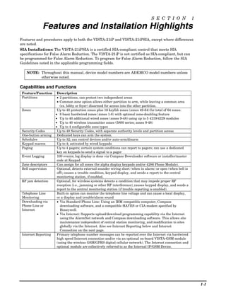
![Programming Overview
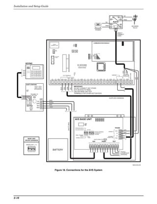
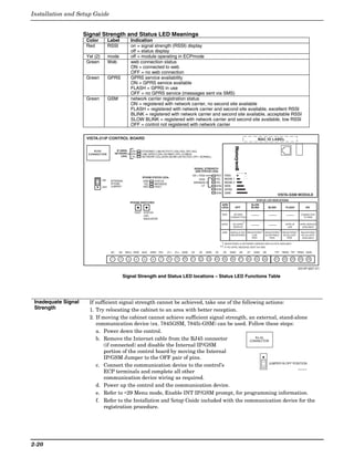
Audio Alarm Verification Using the AVS System with AVS Module and AVST Remote Stations
Connections The AVS system provides audio alarm verification via the phone line.
(AVS System) Refer to the instructions included with the AVS system for installation procedures. The
following is a summary.
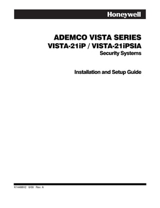
Mounting the AVS Base Unit
As shipped, the AVS Base unit board
comes pre-mounted on its mounting
bracket, which is designed to mount
inside the control cabinet. SECURE
WITH TWO (2)
Refer to the diagram at right. SELF-TAP SCREWS
(SUPPLIED)
a. Position the mounting plate/PC
board assembly in the bottom of
the control’s cabinet. CABINET
SYSTEM TIE-WRAP
b. Slide the mounting plate to the BATTERY LOOP
right so that the plate’s left-hand
ON
ON 4 5
2 3
1
3 4
1 2
tang slides under the cabinet’s tie- TANG
BENEATH
MOUNTING
wrap loop. PLATE
c. Secure the assembly to the cabinet SLIDE ASSEMBLY TO RIGHT UNTIL
using the two self-tapping screws TANG SLIPS UNDER CABINET LOOP
AVS-003-V0
provided.
BATTERY NOTE: When using a 7AH battery, mount the battery vertically on the
bottom left-hand side of the cabinet, with the terminals facing down and right (negative
terminal closest to the PC board bracket).
Wiring the AVS to the Control
The AVS Base unit board has several terminal blocks for making connections to remote
stations, telephone lines, and to the control panel. The AVS base unit connects to the
control’s ECP terminals, with all other ECP devices connecting to the AVS base unit ECP
terminals. See the diagram on the next page for specific wiring connections.
DIP Switch: Set the address AVS DIP switch to device address 11.
IMPORTANT: The AVS should be the only ECP device connected to the control’s
ECP terminals. Connect all other ECP devices (keypads, expander modules, etc.) to
the ECP terminals on the AVS board.
The following summarizes the programming steps for AVS operation (refer to the
Programming Guide for details of the AVS Quick Command options):
a. Install the AVS module according to its instructions.
b. Use one of the control’s AVS Quick Program commands as follows :
• installer code + [#] + 03: enable AVS operation without panel sounds on the AVST
• installer code + [#] + 04: enable AVS operation and enable panel sounds on the
AVST speaker
c. Use data field ∗55 Dynamic Signaling Priority to select the desired reporting paths.
2-15](https://image.slidesharecdn.com/honeywell-vista-21ip-install-guide-120804190306-phpapp02/85/Honeywell-Vista-21IP-Install-guide-21-320.jpg)
![Programming Overview
S E C T I O N 3
Programming Overview
About Programming
• You can program the system at any time, even at the installer's premises prior to the actual installation.
• Programming can also be performed remotely from the installer’s office/home, using an IBM personal
computer, a modem, and Compass downloading software.
• The Real-Time Clock must be set before completing the installation.
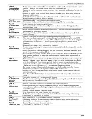
The following is a list of the various Programming modes used to program this system.
Programming Mode… Used to …
Data Field Programming Program basic data fields used for setting the various system options.
Most of the data fields in this system have been programmed for specific default
values. However, some fields must be programmed for each particular installation to
establish its specific alarm and reporting features.
∗29 Menu Mode for IP/GSM For programming the IP/GSM options.
∗56 Zone Programming Assign zone characteristics, report codes, alpha descriptors, and serial numbers for
5800 RF transmitters. See *56 Zone Programming in Section 5. Menu Mode
Programming for procedures for programming zones.
∗57 Function Key Program each of the four alphabet function keys to perform one of several system
Programming operations.
∗58 Zone Programming Similar to ∗56 mode, but provides a faster programming procedure and is intended for
(Expert Mode) those more experienced in programming controls of this type.
∗79 Output Device Mapping Assign device addresses used by 4229 or 4204 Relay modules and map specific relays
and device outputs, and assign unit codes for Powerline Carrier devices.
See About Output Device Programming in Section 5. Menu Mode
Programming for details on setting devices for manual/automatic operation.
∗80 Output Definitions Define up to 48 output definitions which can control the output relays mapped using
*79 Output Device Mapping mode.
∗81 Zone List Programming Create Zone Lists for relay/powerline carrier zones, chime, night-stay, cross zones,
and pager zones.
∗82 Alpha Programming Create alpha descriptors for easy zone identification.
Scheduling Mode Create schedules to automate various system functions.
(code + [#] +64)
Mechanics of Programming
To program the system from a keypad:
• You must use a 2-line Alpha display keypad.
• Both partitions must be disarmed.
Data Field Programming Procedures
Task Procedure
Entering Program Mode A) Press both [∗] and [#] at the same time within 50 seconds after power is applied,
OR
B) After power-up, enter [Installer code (4-1-1-2)] + 8 0 0 (long beep indicates one of the
partitions is armed and system cannot enter program mode).
(method “B” is disabled if you exit Program mode using ∗98)
Go to a Data Field Press [∗] + [Field Number]. A display of “EE” or “Entry Error” means you have entered a
nonexistent field. Simply re-enter [∗] plus a valid field number.
Entering Data When the desired field number appears, simply enter the digits required. The keypad
beeps three times after the last digit is entered and automatically displays the next data
field in sequence.
If entering less than the maximum digits available (e.g., phone number field), enter the
desired digits, then press [∗] to end the entry.
Review a Data Field Press [#] + [Field Number]. The field’s data is displayed, but no changes can be made.
Deleting an Entry Press [∗] + [Field No.] + [∗] (applies only to phone number, account number, and pager
character fields).
3-21](https://image.slidesharecdn.com/honeywell-vista-21ip-install-guide-120804190306-phpapp02/85/Honeywell-Vista-21IP-Install-guide-27-320.jpg)
![Installation and Setup Guide
Interactive Mode Programming (∗56, *57, ∗58, ∗79, ∗80, ∗81, ∗82)
∗
Entering Interactive Mode Press [∗] + [Interactive Mode No.] (for example, ∗56) while in Program Mode. The Alpha
display keypad will display the first of a series of prompts.
After making the appropriate entry, press the [∗] key to accept the entry and continue to
the next prompt.
Loading Factory Defaults/Initializing for Download
To Load Default Entries Press ∗97 while in Program Mode. This resets all data fields to the default values shown
on the Program Form. Use ∗97 only if you wish to return to the original factory-
programmed defaults.
To Initialize Download ID Press ∗96 while in Program Mode. This initializes the system for downloading and resets
all the subscriber account numbers and CSID.
Do not press ✱97 to load defaults if any programming has been done previously—data already
programmed into the system will be changed!
Exiting the Programming Mode
Prevent installer code Press ∗98. Exits Programming Mode and prevents re-entry by:
reentry Installer Code + [8] + [0] + [0]. To enter the programming mode if ∗ 98 was used to exit,
you must first power the system down. Then power up again, and press [∗] and [#] at the
same time, within 50 seconds of powering up.
See field *88 for other Program mode lockout options.
Allow installer code Press ∗99. Exits Programming Mode and allows re-entry by:
reentry Installer Code + [ 8] + [0] + [0] or by: Pressing [∗] and [#] at the same time, within 50
seconds of power-up.
Zone Type Definitions
Zone types define the way in which the system responds to faults in each zone.
Zone Type Description
Type 00 Program a zone with this zone type if the zone is not used.
Zone Not Used
Type 01 • Assign to zones that are used for primary entry and exit.
Entry/Exit • Provides entry delay when zone is faulted if control is armed in the Away, Stay, or Night-Stay
Burglary #1 modes.
• No entry delay provided when the panel is armed in the Instant/Maximum mode.
• Entry delay #1 is programmable for each partition (field *35).
• Exit delay begins whenever the control is armed, regardless of the arming mode selected, and
is programmable (field ✱34).
Type 02 • Assign to zones that are used for entry and exit and require more time than the primary
Entry/Exit entry/exit point.
Burglary #2 • Provides a secondary entry delay, in same manner as entry delay #1.
• Entry delay #2 is programmable for each partition (field *36).
• Exit delay is same as described for Type 01.
Type 03 • Assign to all sensors or contacts on exterior doors and windows.
Perimeter • Provides an instant alarm if the zone is faulted when the panel is armed in the Away, Stay,
Burglary Night-Stay, Instant or Maximum modes.
Type 04 • Assign to a zone covering an area such as a foyer, lobby, or hallway through which one must
Interior Follower pass upon entry (to and from the keypad).
• Provides a delayed alarm (using the programmed entry 1 time) if the entry/exit zone is faulted
first. Otherwise this zone type gives an instant alarm.
• Active when the panel is armed in the Away mode.
• Bypassed automatically when the panel is armed in the Stay or Instant modes;
if armed in Night-Stay mode, zones assigned to zone list 05 (night-stay zone list) are not
bypassed when system armed in Night-Stay mode.
3-22](https://image.slidesharecdn.com/honeywell-vista-21ip-install-guide-120804190306-phpapp02/85/Honeywell-Vista-21IP-Install-guide-28-320.jpg)
![S E C T I O N 4
Data Field Programming
About Data Field Programming
The following pages list this control’s data fields in numerical order. Valid entries for each field are shown in
italics. Explanations and special notes are presented below the entries.
Use the separate Programming Guide to record the data for this installation.
Data field programming involves making the appropriate entries for each of the data fields.
Start Data Field programming by entering the installer code + 8 + 0 + 0.
SIA Guidelines: Notes in certain fields give instructions for programming the VISTA-21iP for False Alarm Reduction.
Fields unique to the VISTA-21iPSIA are indicated by heavy borders and reverse type heading “V21iPSIA” for easy
identification.
System Setup Fields (∗20 – ∗29)
*20 Installer Code *27 Powerline Carrier Device (X-10) House ID
Enter 4 digits, 0-9 0 = A; 1 = B; 2 = C; 3 = D; 4 = E; 5 = F; 6 = G; 7 = H;
The Installer Code can perform all system functions 8 = I; 9 = J; # + 10 = K; # + 11 = L; # + 12 = M;
except it cannot disarm the system unless it was used # + 13 = N; # + 14 = O; # + 15 = P
to arm the system. Powerline Carrier devices require a House ID,
identified in this field. Program Powerline Carrier
*21 Quick Arm Enable devices in interactive modes ∗79, *80 and *81.
0 = do not allow quick arm; 1 = allow quick arm Not intended for fire or UL installations.
If enabled, a user code is not needed to arm the system.
Instead, users can press the [#] followed by an arming *28 Access Code for Phone Module
key to arm the system. However, the user code is always 1-9 = first digit of access code
needed to disarm the system. ∗ or # = second digit of access code
(# +11 for “∗”, or # +12 for “#”)
*22 RF Jam Option You must assign a 2-digit access code for the 4286
0 = no RF jam detection; 1 = send RF jam report Phone Module, if used. Example: If desired access code
If enabled, a report is sent if the system detects an RF is 7∗, then 7 is the first entry, and [#] + 11 (for ∗) is the
jamming signal. second entry.
UL installations must be 1 if wireless devices are used.
NOTE: A 0 in either digit disables the phone module.
*23 Quick (Forced) Bypass Must be 00 for UL Commercial Burglar Alarm
0 = no quick bypass installations.
1 = allow quick bypass (code + [6] + [#] )
Zones bypassed by this function will be displayed after
*29 Menu Mode for IP/GSM Enable
the bypass is initiated. For programming IP/GSM options. See ∗29 Menu Mode
UL installations must be 0 (no forced bypass) section for procedures.
∗
Zone Sounds & Timing (∗31–∗39) ∗
*24 RF House ID Code
00 = disable all wireless keypad usage *31 Single Alarm Sounding Per Zone (per armed period)
01–31 = House ID for partition 1, 2 and common 0 = no limit on alarm sounding per zone
The House ID identifies receivers and wireless keypads. 1 = limit alarm sounding at the bell output to once per
If a 5827 or 5827BD Wireless Keypad or 5804BD arming period for a given zone
Transmitter is being used, a House ID code must be V21iPSIA: If “0” selected, “alarm sounding per zone”
entered and the keypad set to the same House ID. You will be the same as the “number of reports in armed
can assign RF house ID for each partition. period” set in field *93 (1 if one report, 2 if 2 reports,
unlimited for zones in zone list 7).
*26 Chime By Zone List
0 = no zone list (chimes on fault of any entry/exit or
perimeter zone when chime mode on)
1 = use zone list (chimes on fault of specific zones
programmed in zone list 3 when Chime mode on)
If enabled, you can define the specific zones intended to
chime when faulted while the system is in Chime mode.
Use zone list 3 to assign these zones (see ∗81 Zone List
Programming section for details).
4-1](https://image.slidesharecdn.com/honeywell-vista-21ip-install-guide-120804190306-phpapp02/85/Honeywell-Vista-21IP-Install-guide-31-320.jpg)
![Installation and Setup Guide
*32 Fire Alarm Sounder Timeout *38 Confirmation Of Arming Ding
0 = yes; sounder timeout after time selected in field ∗33 0 = no ding; 1 = confirmation ding after arming system
1 = no timeout; sounds until manually turned off 2 = ding after arming from RF button or RF keypad only
This control complies with NFPA requirements for (except 5827/5827BD)
temporal pulse sounding of fire notification appliances. Confirmation of arming is 1/2-sec external sounder “ding.”
Temporal pulse sounding for a fire alarm consists of the If 1 selected, ding occurs when closing report is sent if
following: 3 pulses – pause – 3 pulses – pause – 3 pulses. open/close reporting is enabled, or at the end of Exit
UL fire alarm installations: must be 1. Delay. If 2 selected, ding occurs upon reception of the
wireless arming command.
*33 Alarm Sounder Timeout UL Installations: must be 1 for UL Commercial Burglar
0 = No timeout; 1 = 4 min; 2 = 8 min; 3 = 12 min; 4 = 16 min Alarm installations.
This field determines whether the external sounder will
shut off after time allotted, or continue until manually *39 Power-Up In Previous State
turned off. 0 = always power-up in a disarmed state
1 = assume the system status prior to power down
UL Installations: For residential fire alarm installation,
When the system powers up armed, an alarm will occur
must be set for a minimum of 4 min (option 1); for UL
1 minute after arming if a zone is faulted.
Commercial Burglary installations, must be minimum
of 16 min (option 4). Note that if the previous state was armed Away or Stay,
the system ignores sensor changes for 1 minute, which
*34 Exit Delay allows sensors such as PIRs to stabilize.
00 - 96 = 0 - 96 seconds; 97 = 120 seconds UL Installations: must be 1 (power-up in previous state)
V21iPSIA: 45 - 96 = 45 - 96 secs; 97 = 120 secs SIA Guidelines: must be 1
NOTE: Entries less than 45 will result in a 45-sec delay. V21iPSIA: Feature must be enabled.
The system waits the time entered before arming
entry/exit zones. If the entry/exit door is left open after Dialer Programming (∗40 – ∗50)
this time expires, an alarm will occur. Common zones
use same delay as partition 1.
*40 PABX Access Code or Call Waiting Disable
Enter up to 6 digits if PABX is needed to access an
UL installations: For UL Commercial Burglar Alarm
outside line. Do not fill unused spaces. 0–9, # + 11 for ‘∗’,
and UL Residential Burglar Alarm installations with
# + 12 for ‘#’, # + 13 for a pause (2 seconds)
line security, total exit time must not exceed 60
To clear entries from field, press ∗40∗. If fewer than 6
seconds.
digits need to be entered, exit by pressing [∗].
SIA Guidelines: minimum exit delay is 45 seconds
Call Waiting: If the subscriber’s phone service has
*35 Entry Delay 1 (*35), Entry Delay 2 (*36) “call waiting” (and is not using PABX), enter “*70” (“# +
11”) plus “# + 13” (pause) as the PABX entry to disable
*36 00 - 96 = 0 - 96 seconds; 97 = 120 secs; 98 = 180
“call waiting” during control panel calls. If the
secs; 99 = 240 secs
subscriber does not have “call waiting” and is not using
V21iPSIA: 30-96 = 30 - 96 secs; PABX, make no entry in this field.
97 = 120 secs; 98 = 180 secs; 99 = 240 secs NOTES: 1. The call waiting disable feature cannot be
NOTE: Entries less than 30 will result in a 30-sec delay. used on a PABX line. 2. Using Call Waiting Disable on
a non-call waiting line will prevent successful
Upon entering, the system must be disarmed before the
communication to the central station.
time entered expires, otherwise it sounds an alarm.
Common zones use same delay as partition 1. V21iPSIA: If call waiting is used, enter call waiting disable digits
UL Installations: For UL Residential Burglary Alarm as described above, and also set Call Waiting Disable option in
field *91.
installations, must be set for a maximum of 30 seconds;
entry delay plus dial delay should not exceed 1 min. For
UL Commercial Burglar Alarm, total entry delay may *41 Primary (*41) and Secondary (*42) Phone No.
not exceed 45 seconds. *42 Enter up to 20 digits. 0–9, # + 11 = ‘∗’, # + 12 = ‘#’,
SIA Guidelines: minimum entry delay is 30 seconds # + 13 = pause (2 secs)
If entering fewer than 20 digits, exit by pressing [∗] +
*37 Audible Exit Warning next field number. To clear entries, press ∗41∗ or *42*
0 = no; 1 = yes respectively. Do not fill unused spaces.
Warning sound consists of slow continuous beeps until NOTE: Backup reporting (see field *49) is automatic
the last 10 seconds, and then it changes to fast beeps. only if there is a secondary phone number (field ∗42).
Sound ends when exit time expires.
SIA Guidelines: must be enabled (enter 1) *43 Primary/Secondary Account Numbers
*44 Enter 4 or 10 digits, depending on selection in
V21iPSIA: Feature always enabled; field does not exist.
*45 *48 Report Format field. Enter 0–9; # + 11 = B,
*46 # + 12 = C, # + 13 = D, # + 14 = E, # + 15 = F.
*43: Partition 1 primary. To clear entries: ∗43∗.
*44: Partition 1 secondary. To clear entries: ∗44∗.
*45: Part. 2 prim. To clear entries: ∗45∗.
*46: Part. 2 second. To clear entries: ∗46∗.
4-2](https://image.slidesharecdn.com/honeywell-vista-21ip-install-guide-120804190306-phpapp02/85/Honeywell-Vista-21IP-Install-guide-32-320.jpg)
![Installation and Setup Guide
System Status Report Codes *60 Trouble Report Code
Zone report codes are programmed using interactive ✱56 (0 = no report; 1-F = see description above *59
or ✱58 Zone Programming modes, while system status Sent if a zone has a trouble condition. See UL System
(non-alarm) codes and restore codes are entered in data Reporting Note above *59.
fields *59 - *68, *70 - *76, *89. The actual report code *61 Bypass Report Code
digits that you enter depend upon the particular 0 = no report; 1-F = see description above *59
installation, and should agree with the Central Station Sent when a zone is manually bypassed. See UL System
office receiving the signals. Reporting Note above *59.
3+1 or 4+1 Standard Format: Enter a code in the
first box: 1–9, A, B, C, D, E, or F. Enter #+10 for A (this *62 AC Loss Report Code
reports a 0 on some receivers), #+11 for B, #+12 for C, 0 = no report; 1-F = see description above *59
#+13 for D, #+14 for E, #+15 for F. Timing of this report is random with up to a 4-hour
An entry of 0 in the first box disables a report. Entering delay. If AC restores before the report goes out, there is
0 in the second box advance to the next field. no “AC LOSS” report. See UL System Reporting Note
Expanded or 4+2 Format: Enter codes in both boxes above *59.
(first/second digits) for 1–9 or A–F, as described above. *63 Low Bat Report Code
A 0 in the first box disables a report. A 0 in the second 0 = no report; 1-F = see description above *59
box eliminates the expanded message for that report. Sent when the system’s backup battery has a low-battery
ADEMCO Contact ID® Reporting: Enter a digit in condition. See UL System Reporting Note above *59.
the first box to enable the zone to report. Use a different
digit for each zone until you have used up available *64 Test Report Code
digits. If the number of zones exceeds the number of 0 = no report; 1-F = see description above *59
available digits, begin with digit 1 again. This is an Sent periodically to test that the communicator and
“enabling” code only and is not the actual code sent to phone lines are operational. See System Reporting UL
the Central Station office. Entries in the second boxes Note above *59. Frequency of report is set in Scheduling
are ignored. An entry of 0 in the first box disables the mode (event 11) or by the following key commands:
report. installer code + [#] + 0 + 0 = test report sent every 24 hrs
installer code + [#] + 0 + 1 = test report sent once per week
UL Report codes are required in fields *61, *65, *71, *72, for
installer code + [#] + 0 + 2 = test report sent every 28 days
Each of these modes sets schedule 32 to the selected
UL Commercial Burglar Alarm installations.
repeat option; first test report sent 12 hours after
Report codes are required in fields *60, *62, *63, *64, *70, *73,
*74, *75, *76, for UL Commercial Burglar Alarm installations and command†.
required for Residential Fire Alarm installations. † NOTE: Make sure the Real-Time Clock is set to the proper
time before entering the test report schedule command to
*59 Exit Error Report Code ensure that test reports are sent when expected. (see Setting
0 = no report; 1-F = see description above the Real-Time Clock section)
V21iPSIA: [1] Always enabled. Also see field *69. *65 Open Report Code
0 = no report; 1-F = see description above *59
After arming the system, entry/exit and interior zones
Sent upon disarming the system in the selected
remaining open after exit delay expires cause an alarm
partitions. See UL System Reporting Note above *59.
sound at the keypad and external sounder (keypad also
displays “EXIT ALARM”), and entry delay begins. *66 Arm Away/Stay Report Code
Disarming before the end of the entry delay stops the 0 = no report; 1-F = see description above *59
alarm sounding and no message is sent to the central This option allows for independent programming of
station. The keypad will display “CA” (fixed-word) or Away and Stay reports for each partition, including the
“ALARM CANCELED” (alpha display). common lobby.
If the system is not disarmed before entry delay expires, NOTE: “OPEN” reports are not sent if the associated
an “EXIT ALARM” message (V21iPSIA: also zone alarm closing report is not enabled.
message) will be sent to the central station. The keypad
will display “EA” (fixed-word ) or “EXIT ALARM” (alpha *67 RF Trans. Low Batt. Report Code
display), and alarm sounding continues until the system 0 = no report; 1-F = see description above *59
is disarmed (or timeout occurs). Sent when a transmitter low-battery condition exists.
UL installations: must be enabled if wireless devices
An Exit Alarm condition will also result if a fault occurs
are used.
in an exit or interior zone within 2 minutes following the
end of the exit delay, and an “EXIT ALARM” message *68 Cancel Report Code
will be sent to the central station (except for V21iPSIA, 0 = no report; 1-F = see description above *59
see field *69 Recent Closing report). With Contact ID Sent upon disarming the system after an alarm
format, the message will contain the zone number condition was reported.
and error code 374 (“ALARM–EXIT ERROR”). V21iPSIA: [10] Report enabled.
4-4](https://image.slidesharecdn.com/honeywell-vista-21ip-install-guide-120804190306-phpapp02/85/Honeywell-Vista-21IP-Install-guide-34-320.jpg)
![Installation and Setup Guide
*87 Misc. Fault Delay Time *91 Option Selection
0 = 15 secs 4 = 90 secs 8 = 4 min #+12 = 8 min 0 = none
1 = 30 secs 5 = 2 min 9 = 5 min #+13 = 10 min 1 = Bell Supervision Processing†
2 = 45 secs 6 = 2-1/2 min #+10 = 6 min #+14 = 12 min 4 = using Audio Alarm Verification (AAV) unit
3 = 60 secs 7 = 3 min #+11 = 7 min #+15 = 15 min 8 = Enable Exit delay restart/reset ††
Used with zones assigned to a configurable zone type Select by adding the values of each option. E.g., for both
with fault delay on (configurable zone type digit “6”), AAV and Exit delay restart, enter # + 12 (4 + 8).
and sets a zone response time of 15 seconds to 15 min.
V21iPSIA: Options: Same as listed above.
It can be assigned to zones with sensors that provide a
Call Waiting Disable: 0 = call waiting not used
trouble indication when an oil tank is low, or similar 1 = call waiting disable digits (*70) entered in field *40;
applications for critical condition monitoring where a (when selected, the system dials the entry in field *40 only
non-alarm response is desired. on alternate dial attempts; this allows proper dialing in the
UL: May only be used on non-burglar alarm and non- event call waiting service is later canceled by the user).
fire alarm zones when used on a fire and/or UL burglar
† If bell supervision is selected, you must also cut the red PCB Bell
alarm installation. Supervision jumper.
*88 Program Mode Lockout Options ††“Exit Delay Restart/reset” option allows use of the [∗] key to restart
the exit delay at any time when the system is armed STAY or
0 = standard *98 installer code lockout INSTANT. This feature also enables automatic exit delay reset, which
1 = lockout [∗] + [#] reentry after *98 exit (reentry via resets exit delay if the entry/exit door is re-opened and closed before exit
installer code only) delay time expires after arming AWAY. Automatic Exit Delay Reset
2 = not used; 3 = lockout all local programming after *98 occurs only once during an armed AWAY period.
exit (reentry via downloader only) IMPORTANT: AAV should not be used when Paging or Alarm
Reports are sent to a secondary number unless the monitoring
The following table summarizes the Program mode
zone option is used (which pauses calls). Otherwise, the call to
lockout options: the secondary number by the communicator after the alarm
Exit *88 Reentry By: report will prevent the AAV from taking control of the telephone
Command Entry Installer Power-up† Downloader line, and the AAV “Listen in” session cannot take place.
*99 n/a yes yes yes
UL UL installations using the AAV feature must use the
*98 0 no yes yes
ADEMCO UVCM module (part of the ADEMCO UVS system).
*98 1 yes no yes Exit Delay Restart/Reset must be disabled.
*98 3 no no yes SIA Guidelines: Exit delay should be enabled.
† pressing [∗] + [#] within 50 seconds of power up
*92 Phone Line Monitor Enable
*89 Event Log Full Report Code Entry 1–Timeout:
0 = no report; 1-F = see description above *59 0 = disabled; 1-15 = 1 minute to 15 minutes respectively
If an Event Logging selection is made in field ∗90, a (2 = 2 min, 3 = 3 min, etc.; # + 10 =10 min, # + 11 = 11 min,
message can be sent to the central station receiver # + 12 = 12 min, # + 13 = 13 min, # + 14 = 14 min, # + 15 = 15 min)
when the log is 80% full. If the log becomes full, new Entry 2–Display/Sound:
messages overwrite the oldest messages in the log. 0 = keypad display only when phone line is faulted.
1 = keypad display plus keypad trouble sound when line is
*90 Event Log Enables faulted. Each partition turns off its own trouble sound. No
0 = no event logging; 1 = log Alarm and Restore; 2 = log automatic timeout.
Trouble and Restore 2 = Same as “1” plus programmed output device STARTS.
4 = log Bypass and Restore; 8 = log Open/Close If either partition is armed, external sounder activates. External
sounder will be turned off by normal bell timeout, or by security
x = log combination of events (add value of entries) code plus OFF from either partition (it does not have to be the
This system can record up to 100 system events in a one that was armed).
history log. At any time, the downloader operator can Entry 1: Sets the length of time a phone line fault must
then upload the log and view or print out all or selected remain after detected before the second digit option is
categories of the log. The downloader operator can also activated.
clear the log. Event log can also be viewed at an alpha Entry 2: Selects the desired phone line fault response.
keypad. The display/printout at the central station will Option 2 may be used even if a relay unit or Powerline
show the date, time, event, and description of the carrier device is not connected to the control.
occurrences. If option 2 used, programmed Output Device must
Data Entry Example: To select Alarm/Alarm Restore”
either be programmed to be STOPPED in field ∗80 or
and “Open/Close”, enter 9 (1+ 8); to select all events,
STOPPED by entry of [security code] + [#] + 8 + device
enter #15.
number. Partition in ∗80 should be set to “0,” for STOP.
UL Field *92 must be enabled for fire alarm installations, UL
commercial burglar alarm installations and UL residential
burglar alarm installations.
If the control unit is used on a UL commercial burglar alarm
system which requires 2 methods of remote communication,
then the control unit’s DACT and the other method of signal
transmission must monitor each other against communication
failure and line fault. The fault must be received and
annunciated within 200 seconds of its occurrence.
4-6](https://image.slidesharecdn.com/honeywell-vista-21ip-install-guide-120804190306-phpapp02/85/Honeywell-Vista-21IP-Install-guide-36-320.jpg)
![Data Field Programming
*93 No. of Reports In Armed Period per Zone *97 Command to Reset System to Factory
(Swinger Suppression) Default Values
0 = unlimited number of reports Pressing ∗97 resets all data fields to the factory default
1 = 1 report pair per zone per armed period values (shown on the Program Form).
2 = 2 report pairs per zone per armed period IMPORTANT: Do not press ∗97 to load defaults if any
Selection limits the number of alarm/alarm restore programming has been done previously—data already
message pairs per zone sent to the CS in an armed programmed into the system will be changed!
period and applies to burglary zones only.
SIA Guidelines: Must be set for option 1 or 2. *98 Command to Exit Program Mode (with
installer code lockout)
V21iPSIA: Exits Programming Mode and prevents re-entry by:
Report Pairs: 1 = 1 report pair; 2 = 2 report pairs
Installer Code + [8] + [0] + [0].
Unlimited Reports Enable:
0 = restrict reports to the setting in entry 1 To enter the programming mode if ∗ 98 was used to
1 = unlimited reports for zones listed in zone list 7; exit, you must first power down the system. Then power
(use zone list 7 to list zones that require unlimited up again, and press [∗] and [#] at the same time, within
reporting; these zones ignore the setting in entry 1) 50 seconds of powering up. See field *88 for other
Program mode lockout options.
*94 Download Phone Number
Enter up to 20 digits as follows: 0–9, # +11 for “∗”, *99 Command to Exit Program Mode
# + 12 for “#”, # + 13 for a pause. Exits Programming Mode and allows re-entry by:
Enter the phone number of the downloading computer. Installer Code + [ 8] + [0] + [0]
Do not fill unused spaces. End field by entering ∗. To or by: Pressing [∗] and [#] at the same time, within 50
clear entries from field, press ∗94∗. seconds of power-up.
UL: Up/downloading via phoneline may be performed Pager Programming Fields
only if a technician is at the site. The system can send various reports to up to four
Up/downloading via the Internet has not been pagers.
evaluated by UL. To program pager reporting, do the following:
1. Enter the pager phone number(s), preface characters,
*95 Ring Count For Downloading and pager report options in data fields *160 - *171:
0–15 = number of rings before control picks up phone line.
2. Enable Pager Delay, if desired, in field *172 (delays
Refer to the chart below and program accordingly.
phone answer down- alarm reporting for ALL pagers).
module machine loading Set field ∗95 to… 3. Make sure appropriate user open/close pager reports
yes no no 1-14 (not 0) are enabled (see Security Codes, Assigning
yes yes no higher than number of Attributes in Section 6. System Communication
rings set on answer and Operation). Users that perform actions in
machine (e.g., if ans.
machine is 4 rings, set this
partition 1 will, if enabled, attempt to report to all
field to 5). This allows pagers enabled for open/close reporting in partition
access to the phone 1. Users that perform actions in partition 2 will, if
module if the answer enabled, attempt to report to all pagers enabled for
machine is off. open/close reporting in partition 2.
yes no yes 1-14 (not 0)
yes yes yes 15 (bypasses answer
4. If using latchkey pager report, define the latchkey
machine†) report schedule using Scheduling mode (master code
no no no 0 + [#] [6] [4] then select event type 03). System must
no yes no 0 be armed for the Latchkey report to be sent.
no no yes 1-14 5. If using a function key to manually send a message
no yes yes 15 to a pager, use *57 Function Key Menu mode to
† NOTE: If “15” is entered to bypass an answering machine, define the key (function 01).
and a 4286 Phone Module is included in the system, you 6. If reporting zone alarms and troubles to a pager, use
should note the following: *81 Zone List menu mode to assign the zones
When calling in from an off-premises phone, the user associated with each pager (zone lists 9-12).
should make the initial call, allow 1 or 2 rings only, then
hang up, then call again. The phone module will now seize *160 Pager 1 Phone No.
the line, and 2 long tones sound, followed by the usual voice Enter up to 20 digits.
prompt for the access code. If this procedure is not followed,
If entering fewer than 20 digits, exit by pressing [∗] +
phone module operation will not be possible.
next field number. To clear entries, press ∗160∗.
*96 Command to Initialize CSID and Subscriber
Account Number
Use this command, if necessary, to reset all subscriber
account numbers and the internal CSID to the factory
default values.
4-7](https://image.slidesharecdn.com/honeywell-vista-21ip-install-guide-120804190306-phpapp02/85/Honeywell-Vista-21IP-Install-guide-37-320.jpg)
![Installation and Setup Guide
*161 Pager 1 Characters *167 Pager 3 Characters
Enter up to 16 characters. Enter up to 16 characters
Up to 16 optional characters may be sent as a prefix to See field ∗161 for explanation of entries. If fewer than
the 7-digit system status code sent to Pager #1 (if used). 16 characters, exit by pressing [∗] and next field
Phone number in field *160 must have been entered. If number. To clear entries, press ∗167∗.
fewer than 16 characters, exit by pressing [∗] and next
field number. To clear entries: press ∗161∗. *168 Pager 3 Report Options
The 16 characters may be composed of the following: See pager 1 reports, field *162, except use zone list 11
PIN number, Subscriber account number, *169 Pager 4 Phone No.
∗ (enter # + 11 to send ∗), # (enter # + 12 to send #), Enter up to 20 digits
Pause (enter # + 13 to allow a 2-second pause),† If entering fewer than 20 digits, exit by pressing [∗] +
special character(s) the user may decide to transmit next field number. To clear entries, press ∗169∗.
† Some paging systems require pause(s) before the prefix.
The Pager format for the 7-digit status code is defined *170 Pager 4 Characters
as follows: XXX-YYYY where: Enter up to 16 characters
XXX = 3-digit event code: 911 = Alarm, 811 = See field ∗161 for explanation of entries. If fewer than
Trouble, 101 = Opening (disarm), 102 = 16 characters, exit by pressing [∗] and next field
Closing (arm AWAY) number. To clear entries, press ∗170∗.
YYYY = 4-digit user or zone number (depending on
type of event). The first digit indicates partition (0 = *171 Pager 4 Report Options
system, 1 = part 1, 2 = part 2, 3 = common), followed See pager 1 reports, field *162, except use zone list 12
by the 3-digit user or zone number. *172Pager Delay Option for Alarms
Display Example 1. 9 1 1 – 1 0 0 4 Indicates an alarm 0 = none; 2 = 2 minutes; 1 = 1 minute; 3 = 3 minutes
(911) caused by a fault in zone 4 (0004) in part. 1. This field determines the delay of alarm reports to the
Display Example 2. 1 0 2 – 2 0 0 5 Indicates the system pager. This gives the Central Station enough time to
is reporting a closing–system arming (102) by User 5 verify the alarm report that it received, before the
(0005) in partition 2. dialer attempts to dial the pager.
*162 Pager 1 Report Options This delay is for ALL pagers in the system
0 = No reports sent; 1 = Open/close for all users enabled Miscellaneous System Fields
to page†; 4 = All alarms and troubles
5 = All alarms, troubles, and open/close for all users *174 Clean Me Option
enabled to page 0 = disable; 1 = enable
12 = Alarms and troubles for zones entered in zone list 9 This is a maintenance feature for ESL 2-wire smoke
13 = Alarms and troubles for zones listed in zone list 9 detectors on Zone 1. If used, this option limits the
and open/close for all users enabled to page
number of smoke detectors to a maximum of 10, rather
Enter the types of reports to be sent to Pager 1 for each
than 16. To enable the “clean me” feature, a time
partition.
response setting of “3” (1.2 seconds) must be entered in
† Reports to pager only when arming (close)/disarming (open)
∗56 Zone Programming for zone 1.
from a keypad using a security code; auto-arming/disarming,
arming with assigned button, and keyswitch arming do not *177 Device Duration 1, 2
send pager messages.
0 = 15 secs 4 = 90 secs 8 = 4 min #+12 = 8 min
*163 Pager 2 Phone No. 1 = 30 secs 5 = 2 min 9 = 5 min #+13 = 10 min
up to 20 digits 2 = 45 secs 6 = 2-1/2 min #+10 = 6 min #+14 = 12 min
3 = 60 secs 7 = 3 min #+11 = 7 min #+15 = 15 min
If entering fewer than 20 digits, exit by pressing [∗] +
These entries set the duration for output action options
next field number. To clear entries, press ∗163∗.
5 (duration 1) and 6 (duration 2) programmed in ∗80
*164 Pager 2 Characters Output Function Programming.
up to 16 characters
See field ∗161 for explanation of entries. If fewer than
*181 50/60 Hz AC Operation
0 = 60 Hz; 1 = 50 Hz
16 characters, exit by pressing [∗] and next field
Select the type of AC power applied to the control
number. To clear entries, press ∗164∗.
(option is used for Real-Time Clock synchronization)
*165 Pager 2 Report Options
See pager 1 reports, field *162 for entries, except use
zone list 10
*166 Pager 3 Phone No.
Enter up to 20 digits
If entering fewer than 20 digits, exit by pressing [∗] +
next field number. To clear entries, press ∗166∗.
4-8](https://image.slidesharecdn.com/honeywell-vista-21ip-install-guide-120804190306-phpapp02/85/Honeywell-Vista-21IP-Install-guide-38-320.jpg)
![Data Field Programming
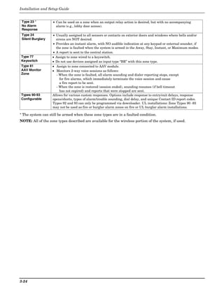
Configurable Zone Type Fields Configurable Zone Type Options
Auto Restore (entry 2): Faults on zones set for this option are
• The system allows you to define up to four custom cleared; restore messages sent upon restoral of faults.
zone types based on the options described at right.
Vent Zone (entry 2): Zones set for this option are ignored if
• All configurable zone types can be programmed via faulted when arming the system, but are protected if the zone
the downloader. is later restored (e.g., an open window can be ignored when
• Configurable zone types 90 and 91 can also be arming, but if the window is later closed, it will be protected;
programmed from a keypad using data fields *182- opening the window again causes an alarm.)
*185. Bypass Disarmed (entry 4): Zones set for this option can be
• IMPORTANT: Be careful when selecting combinations bypassed only while the system is disarmed.
of options for configurable zone types. Contradictory Bypass Armed (entry 4): Zones set for this option can be
options can cause unpredictable results. bypassed when the system is armed.
UL installations: Do not configure zones as fire alarm Dial Delay (entry 6): Alarms on zones set for this option
or UL burglar alarm zones. participate in dial delay central station reporting, if system
dial delay enabled in field *50.
*182 Configurable Zone Type 90 Fault Delay (entry 6): Faults on zones set for this option are
0-15 = values for each of 10 entries (0-9, # + 10 = 10, delayed by the time set in field *87. Do not use this option if
# + 11 = 11, # + 12 = 12, # + 13 = 13, # + 14 = 14, # + 15 = 15) using entry/exit delay for this zone type.
Enter the appropriate value for each entry, 1-10, based Faults Display (entry 7): Selects how faults on zones set for
on the charts on the next page. To calculate the value this zone type are displayed.
for each entry, add the values of the selected options in Power Reset/Verification (entry 7): Selects whether the
each of the entry’s columns shown in the respective system resets power (when user enters code + OFF), and
chart (one option per column). For example, to program whether the system performs alarm verification (see
entry 2 for “alarm response to short,” “auto restore on,” description for zone type 16 in Zone Type Definitions section)
but not a “vent zone,” enter 5 (“1” for alarm short + “4” when a fault occurs on these zones.
for auto restore-yes + “0” for vent zone-no). Use Entry Delay (entry 8): Selects whether to use the
system’s entry delay times.
*183 Zone Type 90 Report Codes Use Exit Delay (entry 8): Selects whether to use the system’s
90 ALARM ID: XXX exit delay time.
TROUBLE ID: XXX Interior Type (entry 8): Zones set for this option are treated
same as standard zone type 4 (bypasses when armed STAY,
Enter the desired 3-digit Contact ID® report codes for faults displayed).
alarms and troubles occurring on zones assigned to this Alarm Sounds (entry 9): Selects the type of alarms sound for
zone type. Use existing Contact ID® codes, if zones set for this zone type.
appropriate, or define unique codes in CID code range
Bell Timeout (entry 9): Alarm sounding on zones set for this
750-789. Press [∗] to accept and continue. option remain for the duration set in fields *32 / *33.
NOTE: Zone alarm report codes (prompt in ∗56 Menu Fire Zone (entry 9): Zones set for this option respond in the
mode) and trouble report code (∗60) and relevant same manner as if programmed for zone type 9. Do not set fire
restore codes (∗70, ∗71) must be enabled in order for the zones to respond as a “fault” in entries 1-6.
configurable zone type codes to be reported. Trouble Sounds (entry 10): Selects the type of trouble sounds
Important Notice on Report Codes: To avoid for zones set for this zone type (periodic beeps = once every 30
confusion at the central station, it is recommended that seconds; trouble beeps = rapid beeping).
existing Contact ID® codes be used with configurable Chime Enable (entry 10): Zones set for this option cause a
zone types whenever possible. See list in System chime when Chime mode is on.
Communication section and/or check with the central
station for a complete list of Contact ID® report codes.
If none of the codes are suitable, choose a code in the
reserved range of 750-789 and make sure to define the
code with your central station.
*184 Configurable Zone Type 91
0-15 = values for each of 10 entries (see field *182 for
explanation of entries.)
*185 Zone Type 91 Report Codes
91 ALARM ID: XXX See field *183 for explanation of
TROUBLE ID: XXX entries and read the Important
notice on using these codes.
4-9](https://image.slidesharecdn.com/honeywell-vista-21ip-install-guide-120804190306-phpapp02/85/Honeywell-Vista-21IP-Install-guide-39-320.jpg)
![Installation and Setup Guide
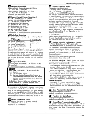
Configurable Zone Type Charts
ENTRY 1 ENTRY 2
Response when system disarmed and zone is: Auto
Intact EOL Open Shorted Restore Vent Zone
RF zone normal RF zone N/A RF zn off-normal
0 = normal 0 = normal 0 = normal 0 = no 0 = no INTACT OPEN SHORTED
EOL
1 = alarm 4 = alarm 1 = alarm 4 = yes 8 = yes ZONE-003-V0
2 = trouble 8 = trouble 2 = trouble Zone Conditions Represented
3 = fault 12 = fault 3 = fault in Entries 1-6
see note 5 see note 6
Entry 1 = EOL + Open Entry 2 = Short + auto restore + vent zone
Configurable Zone Type Notes
ENTRY 3 ENTRY 4
1. Do not use the “fault delay” option
Response when armed STAY and zone is: Byp. when Byp. when with a configurable zone type if it
Intact EOL Open Shorted disarmed armed
is set for an entry or exit delay,
RF zone normal RF zone N/A RF zn off-normal
otherwise unpredictable results
0 = normal 0 = normal 0 = normal 0 = no 0 = no
1 = alarm 4 = alarm 1 = alarm 4 = yes 8 = yes may occur.
2 = trouble 8 = trouble 2 = trouble 2. To create an interior type zone,
3 = fault 12 = fault 3 = fault
select “respond as interior zone
see note 5 see note 6
type” (entry 8, interior type = yes),
Entry 3 = EOL + Open Entry 4 = Short + byp. disarmed + byp. armed
and set zone response to “fault” in
ENTRY 5 ENTRY 6 entries 3-4 to ensure fault
Response when armed AWAY and zone is: Dial Delay Fault Delay displays; do not set as “normal,”
Intact EOL Open Shorted (see field *50) (see field *87) “alarm,” or “trouble.”
RF zone normal RF zone N/A RF zn off-normal
0 = normal 0 = normal 0 = normal 0 = no 0 = no 3. Do not set fire zones to respond as
1 = alarm 4 = alarm 1 = alarm 4 = use delay 8 = use delay a “fault” (entries 1-6), otherwise
2 = trouble 8 = trouble 2 = trouble faults will not display unless the
3 = fault 12 = fault 3 = fault see note 1 [∗] key is pressed.
see note 5 see note 6
Entry 5 = EOL + Open Entry 6 = Short + dial delay + fault delay 4. 4219/4229 modules must use
EOLRs or unpredictable results
ENTRY 7 ENTRY 8 may occur.
Display Faults Power Reset/ Use Entry Use Exit Respond as 5. RF Zones: The “open” options in
Verification Delay 1/2 Delay Interior Type entries 1, 3, and 5 are not
0 = show alarms 0 = no 0 = no 0 = no 0 = no applicable for RF zones. Use the
when armed 4 = power reset 1 = delay 1 4 = use exit 8 = yes “intact EOL” option for normal RF
& disarmed after fault 2 = delay 2 delay
(with code +
zone conditions and “shorted” for
1 = don’t show see note 2
alarms when OFF) off-normal RF zone conditions.
armed (show 12 = verification 6. a. Zone-Doubling/Double-
alarms, trbles, (see zone
faults when type 16) Balanced: A short on either
disarmed) zone of a zone-doubled pair or
3 = never show on a double-balanced zone
any alarms, causes a tamper condition.
trbles, faults b. For double-balanced zones, this
Entry 7 = fault display + power Entry 8 = entry delay 1/entry delay 2 + exit delay + entry must be “0”.
reset/verification interior zone type
c. For zone-doubled zones, both
ENTRY 9 ENTRY 10 zones of the doubled pair must
Alarm Sounds Use Bell Respond as Trouble Chime when Chime be assigned the same response
Timeout Fire Zone Sounds Mode On to a short.
0 = none 0 = no 0 = no 0 = none 0 = no
1 = steady 4 = yes 8 = yes 1 = periodic 4 = yes
keypad beep
2 = steady bell see fields *32, see zone type 2 = trouble
and keypad *33 09; see note 4 beeps
3 = pulsing bell
and keypad
Entry 9 = alarm sounds + bell timeout + fire zone Entry 10 = trouble sounds + chime
4-10](https://image.slidesharecdn.com/honeywell-vista-21ip-install-guide-120804190306-phpapp02/85/Honeywell-Vista-21IP-Install-guide-40-320.jpg)

![Installation and Setup Guide
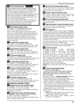
Enter Zn Num. Zone Number
(00 = Quit) 10 wired 01-08 (and 09-48†); wireless 09-48; RF button zones 49-64
91 = addr. device report enable; 92 = duress report enable; 95, 96, 99 =emerg. zones
[∗] to continue; 00 to quit † if zone expanders are used.
Enter the zone number that you wish to program. Zone 10 has been entered in the example
display at left.
Enter a report code for zone 91 to enable addressable device reporting.
Enter a report code for zone 92 to enable duress reporting.
95, 96, 99 are emergency (panic) key zones.
Zn ZT P RC In: L Summary Screen
10 00 1 10 RF: 1
[∗] to continue
A summary display appears.
OR
“IN: L” appears for wireless zones and indicates input type and loop.
Zn ZT P RC In: AD “IN: AD” appears for hardwire expansion zones (AW) and indicates the module’s address
10 00 1 10 AW: 07 (AD), which is based on the zone number.
OR “HW: RT” appears for hardwire zones and indicates configuration (EOL, NO, NC, zone
Zn ZT P RC HW: RT doubling, double-balanced) and response time selection.
10 00 1 10 EL 1
Zone Type (ZT)
10 Zone Type See table below.
Perimeter 03 Each zone must be assigned to a zone type, which defines the way in which the system
responds to faults in that zone. Enter the Zone Type code from the list below:
Note: If 00 is entered, Delete Zone ? will be displayed.
00 = Not used 07 = 24-Hr Audible 20 = Arm–STAY*
01 = Entry/exit #1 08 = 24-Hr Aux 21 = Arm–AWAY*
02 = Entry/exit #2 09 = Fire 22 = Disarm*
03 = Perimeter 10 = Interior w/Delay 23 = No Alarm Resp
04 = Interior Follower 12 = Monitor Zone 24 = Silent Burglary
05 = Day/Night 14 = Carbon Monoxide** 77 = Keyswitch
06 = 24-Hr Silent 16 = Fire w/Verify 81 = AAV Mon. Zone
*5800 button-type transmitters only 90-91 = Configurable
** For wireless zones set for zone type 14, use only compatible wireless carbon monoxide detectors (ex. 5800C0)
10 Partition Partition No. (P)
1-3 = partition (3 = common); [∗] to continue
1 Enter the Partition number for this zone. Partition 1 is shown entered.
10 Report Code Report Code (RC)
First Digit: 1-9, 10 for 0, 11 for B, 12 for C, 13 for D, 14 for E, 15 for F
1st 01 2nd 00 10 00 to disable
Second Digit: same as above; [∗] to continue
Enter the report code for this zone, which consists of 2 hexadecimal digits, each in turn
consisting of 2 numerical digits. For example, for a report code of “10,” enter 01 and 00.
For Contact ID®, entering any non-zero entry as the first digit enables the report code for
this zone. Refer to the System Communication section for information about report codes
and formats.
02 HARDWIRE TYPE Hardwire Type
0 = EOL; 1 = NC; 2 = NO; 3 = zn doubling (ZD); 4 = dble-balanced (DB)
EOL 0
[∗] to continue
This prompt appears only for zone numbers 02-08.
Zone 1 is automatically set for EOL operation.
02 Response Time Response Time (RT)
0 = 10mSec; 1 = 350mSec; 2 = 700mSec; 3 = 1.2 seconds; [∗] to continue
1 This prompt appears only for hard-wired zones 01-08 (zone 02 is the display shown).
Option 3: used for “clean me” option on zone 1 (see field ∗174).
NOTE: If zone doubling is being used, the response time selected for zones 02-08
automatically applies to each zone’s associated doubled zone.
5-2](https://image.slidesharecdn.com/honeywell-vista-21ip-install-guide-120804190306-phpapp02/85/Honeywell-Vista-21IP-Install-guide-44-320.jpg)
![Menu Mode Programming
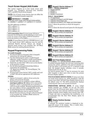
10 INPUT TYPE Input Device Type (In)
2 = AW (Aux wired zone)
RF TRANS 3 3 = RF (supervised RF transmitter)
4 = UR (unsupervised RF transmitter)
5 = Button type RF transmitter (unsupervised).
[∗] to continue
This prompt is skipped for zones 2-8, or 2-16 if zone-doubling was enabled at “Hardwire
Type” prompt.
All of the RF transmitters have one or more unique factory-assigned input (loop) ID codes.
Each of the inputs requires its own programming zone (e.g., a 5804's four inputs require
four programming zones).
RF Transmitters can be enrolled as one of the following types:
Type Description
RF Sends periodic check-in signals, as well as fault, restore, and low-
(Supervised RF) battery signals. The trans. must stay within receiver's range.
UR Sends all the signals that the “RF” type does, but the control does
(Unsupervised RF) not supervise the check-in signals. The transmitter may therefore be
carried off-premises.
BR Sends only fault signals. It will not send a low-battery signal until it
(Unsupervised is activated. The transmitter may be carried off-premises.
Button RF)
NOTE:
• For the built-in hardwired zones, the Input Device type is automatically displayed as HW
and cannot be edited.
• To change the input type of a previously programmed wireless device (type RF, UR, BR)
to a wired zone (type AW), you must first delete transmitter’s serial number (see To
Delete A Serial Number prompt on next page)
10 INPUT S/N: L Serial number Entry and Loop Number Entry
[∗] to continue
A022-4064 1 Used only when enrolling wireless transmitters.
a. Transmit two open/close sequences. If using a button-type transmitter, press and
release the button twice, but wait about 4 seconds before pressing the button the second
time.
OR
b. Manually enter the 7-digit serial number printed on the label of the transmitter. Then
press the [✱] key – the cursor will move to the “L” position. You can edit the loop
number, if necessary. When the loop number is acceptable, press [✱].
c. Press key [C] to copy the serial number previously enrolled (used when programming a
transmitter with several input loops).
10 INPUT S/N L Loop Number Change
[∗] to continue
A022-4064 ? NOTE: If the [C] key is used to copy the previously enrolled serial number, the cursor will
move to the Loop column (L) with the previous serial number displayed, and display a
highlighted question mark for the loop number.
Enter the loop number and press [✱]. The system will now check for a duplicate serial/loop
number combination.
10 INPUT S/N L Enroll Summary
[∗] to continue
A022-4064 1 If the serial/loop number combination is not a duplicate in the system, a display showing
the serial number and loop number entry will appear.
XMIT TO CONFIRM Confirmation Option
[∗] to continue
PRESS ✱ TO SKIP This prompt will only appear if you answered “Yes” at the first prompt in this section.
The system will enter a confirmation mode so that the operation of the actual programmed
input can be confirmed.
Activate the loop input or button that corresponds to this zone.
5-3](https://image.slidesharecdn.com/honeywell-vista-21ip-install-guide-120804190306-phpapp02/85/Honeywell-Vista-21IP-Install-guide-45-320.jpg)
![Installation and Setup Guide
Entd A022-4063 1 If Serial or Loop Numbers do not match after activating the transmitter
Rcvd A022-4064 1
[∗] to continue
If the serial number transmitted does not match the serial number entered, a display
similar to the one shown appears. If the loop number does not match, it will also be
displayed.
If so, activate the loop input or button on the transmitter once again. If a match is not
obtained (i.e., summary display does not appear), press the [#] key twice and then enter (or
transmit) the correct serial number.
10 INPUT S/N: L To Delete a Serial No.
0 in loop number field = delete serial number; # = undo deletion; [∗] to continue
A000-0000 0 To delete an existing serial number, enter 0 in the loop number field. The serial number
will change to 0's.
If 0 was entered in error, simply re-enter the loop number or press [#], and the serial
number will return to the display.
Zn ZT RC In: L Summary Screen
[∗] to continue
10 03 10 RF: 1s If the serial number transmitted matches the serial number entered, the keypad will
beep 3 times and a summary display will appear, showing that zone's programming.
Note that an “s” indicates that a transmitter’s serial number has been enrolled.
Press [∗] to accept the zone information and continue.
PROGRAM ALPHA? Alpha Descriptors
0 = no; 1 = yes; [∗] to continue
0 = NO 1 = YES 0
If you want to program descriptors for zones now, enter 1 (Yes) and refer to the Alpha
Descriptor Programming section for available descriptors.
E N TE R Z N N U M . Next Zone Number
[∗] to continue; 00 = quit
(00 = QUIT) 11 If 0 (No) was entered above, the system will return you to the ENTER ZN NUM. prompt
for the next zone.
When all zones have been programmed, enter 00 to quit.
Completing Zone Programming
• When you have finished programming all zones, test each zone using the system’s TEST mode.
• Do not use the Transmitter ID Sniffer Mode for checking wireless transmitting devices, as it will
only check for transmission of one zone on a particular transmitter, NOT the zones assigned to each
additional loop.
NOTE: Following the successful enrollment of each wireless device, note the device serial number in the
appropriate column on the ENROLLED TRANSMITTERS worksheet in the Programming Form; then enter
the other information (zone number, zone type, loop number, etc.) relevant to that device.
∗58 Expert Programming Mode Procedures
This method is designed for use by installers with previous experience in programming ADEMCO control
panels. This mode is also used to program wireless keys using pre-defined templates.
Start Expert Programming mode by pressing ✱58 while in Data Programming mode.
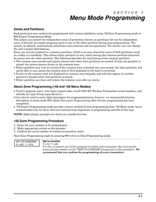
SET TO CONFIRM? Confirm?
0 = no; 1 = yes; [∗] to continue
0 = NO 1 = YES 0 This display appears upon entry into this mode.
The default is 0 (No).
If 1 (Yes) is entered, you will be prompted to confirm each transmitter after entering the
serial and loop numbers (at the “XMIT TO CONFIRM” prompt later).
5-4](https://image.slidesharecdn.com/honeywell-vista-21ip-install-guide-120804190306-phpapp02/85/Honeywell-Vista-21IP-Install-guide-46-320.jpg)
![Menu Mode Programming
Zn ZT P RC HW: RT Summary Screen
01 09 1 10 EL 1
01-64 = zone number; [∗] to continue; 00 = quit
OR [D] to go to prompts for wireless key programming templates
A summary screen appears, showing zone 1’s currently programmed values.
Zn ZT P RC IN: L Enter the zone number being programmed, then press [∗], which displays a summary
10 00 1 10 :RF – screen for that zone. See next prompt (zone 10 in this example).
If programming a wireless key, press the [D] key then skip to the Wireless Key
Programming Templates section following this section. When [D] is pressed, you can choose
from a series of preset templates for easy programming of wireless key zones.
When all zones have been programmed, press 00 at this prompt to quit this menu mode.
Zn ZT P RC IN: L Zone Programming
ZT = see Zone Type chart shown in *56 Menu Mode “Zone Type” prompt
10 00 1 10 RF 1 P = partition 1, 2, 3 (common); RC = 1 (send CID report); 0 (no report)
IN = input type; L = loop number
[∗] to continue
A summary screen with the selected zone’s current programming appears.
Begin programming zone information as follows:
• Enter Zone Type (ZT), Partition (P), Report Code (RC; 0-9 only; use *56 mode to enter
hex codes), and Input Device Type (IN)* sequentially, but not the Loop No. (L).
• Use the [A] (Advance) and [B] (Back) keys on the keypad to move the cursor within the
screen.
• Use the [C] key to copy the previous zone’s attributes.
Press [✱] to save the programming and continue to the serial number/loop number prompt.
If needed, you can press the [#] key to back up without saving.
* If HW (hardwired) or AW (Auxiliary) is entered for Input Device Type, the next screen
will be similar to the prompt shown, except that HW or AW will be displayed under “IN”.
If RF, BR, or UR is entered, a prompt for Serial and Loop number will be displayed, as
follows.
10 INPUT S/N: L Serial number
S/N = serial number; L = loop number; [∗] to continue
AXXX-XXX – Manually enter the serial number (found on the transmitter label), by typing digits in the
“X” locations, using the [A] (advance) or [B] (back) keys as required. You can also perform
two open and close sequences; for button-type transmitters that means pressing and
releasing the button twice.
NOTE: If you want to copy the previous zone’s serial number, press the [C] key.
Press [✱] to advance to the loop number, then enter loop number.
Press [✱] to accept the existing serial and loop number and continue to the “Confirm”
prompt below. If necessary, press [#] to back up and re-enter or edit the serial number.
10 INPUT S/N: L To Delete a Serial Number
[∗] to continue
A000-0000 0 To delete an existing serial number, enter 0 in the loop number field. The serial number
will change to all 0's as shown.
If 0 was entered in error, simply re-enter the loop number, and the serial number will
return to the display.
10 XMIT TO CONFIRM Confirm
PRESS ✱ TO SKIP
[∗] to continue
The prompt to confirm appears. This prompt will only appear if the first prompt after
entering ✱58 was answered “Yes.” To confirm, activate the loop input or button that
corresponds to this zone.
The system checks for duplicate. If a duplicate exists, a long error beep will sound.
Press [#] to back up and re-enter the serial and/or loop number.
5-5](https://image.slidesharecdn.com/honeywell-vista-21ip-install-guide-120804190306-phpapp02/85/Honeywell-Vista-21IP-Install-guide-47-320.jpg)
![Installation and Setup Guide
Entd A022-4063 If Serial or Loop Numbers do not match after activating the transmitter
[∗] to continue
Rcvd A022-4064 If the serial/loop number combination transmitted does not match the serial and loop
number entered, a display similar to the one below will appear. If the loop number does
not match, it will also be displayed. If so, activate the transmitter’s loop input or
button one or more times.
If a match is still not obtained (i.e., summary display does not appear), press the [#] key
twice and enter the correct loop input or, if correct, press [#] again and then enter the
correct serial number.
Zn ZT P RC In L Summary Screen
If the serial number transmitted matches the serial number entered, the keypad will beep
10 03 1 10 RF: 1s 3 times and a summary display will appear, showing the programmed information for that
Note that an “s” indicates zone.
that a transmitter’s serial
number has been Press [∗] to begin programming the next zone. See first “Summary Screen” prompt
enrolled. paragraph on previous page.
To exit this mode, enter 00 at the Summary Screen prompt.
Wireless Key Programming Templates
This procedure programs the wireless keys, but a key is not active for arming/disarming until it is
assigned to a user number (see System Operation section, assigning attributes command).
Enter this mode by pressing the D key while at the *58 Menu mode Summary Screen. The following prompts
appear.
TEMPLATE ? Template Number
1–3 = 5804 templates; 4–6 = 5804BD templates
1–6 1 • Enter Template number 1–6 (see chart on next page).
See the defaults provided for each template in the chart that follows these procedures.
• Select from templates. Press [∗] to display template (1 shown selected).
NOTE: If necessary, press [#] to back up and re-enter template number.
• Press [#] if you want to return to *58 Menu mode summary screen.
L 01 02 03 04 Template Display
• When [∗] is pressed, the selected template will be displayed.
T 23 22 21 23
Top line of display represents loop numbers; bottom line represents zone type assigned
for each loop.
• Press [∗] to accept template.
PARTITION Partition
1 = partition 1; 2 = partition 2
1 • Enter the partition in which the key is to be active, then press [∗] to continue.
ENTER START ZONE Start Zone Number
• The system will search for the highest available consecutive 4-zone group (the four zones
00 = QUIT 36
in the case of the 5804 and 5804BD), and display the lowest zone number of the group.
If you want to start at a different zone, enter the zone desired, and press [✱]. If that zone
number is displayed, the system has the required number of consecutive zones available,
beginning with the zone you entered. If not, the system will again display a suggested
zone that can be used.
If the required number of consecutive zones is not available at all, the system will display
“00”.
To quit this mode and return to *58 Menu mode, enter 00 at this prompt.
• Press [∗] to accept.
INPUT S/N L Serial Number
• Manually enter the serial number printed on the label for the wireless key or press and
AXXX-XXXX –
release the button to transmit its serial number.
• Press [∗] to accept the serial number. The system will check for a duplicate.
• If necessary, press the [#] key to back up without saving, and re-enter the serial number.
• Use the [A] key to move forward within the screen, and the [B] key to move backward.
5-6](https://image.slidesharecdn.com/honeywell-vista-21ip-install-guide-120804190306-phpapp02/85/Honeywell-Vista-21IP-Install-guide-48-320.jpg)
![Menu Mode Programming
XMIT TO CONFIRM Confirm
[∗] to continue
PRESS ✱ TO SKIP
• If “Yes” was entered at the SET TO CONFIRM? prompt previously (see first prompt
following entry into the ∗58 Expert Programming Mode), the display on the left will
appear. Confirm serial and loop numbers by activating the wireless key.
IMPORTANT:
When confirmed, the key is not active for arming/disarming until it is assigned to a user
number (using the assigning attributes command, attribute “4”). See System Operation
section for procedure.
Entd A022-4063 Not Confirmed
[∗] to continue
Rcvd A022-4064 If the serial number transmitted does not match the serial number entered, a display
similar to the one shown will appear. If the loop number does not match, it will also be
displayed.
If so, activate the button on the wireless key once again. If a match is not obtained (i.e.,
summary display does not appear), press the [#] key and then enter the correct serial
number.
If the serial number transmitted matches the serial number entered, the keypad will beep
3 times and will return you to the Zone Number prompt to enter the starting zone for the
next wireless key.
Or you can return to *58 Menu mode by pressing 00 at the Zone Number prompt.
NOTE: Following the successful enrollment of each wireless device, remove ONE of the
serial number labels from the device and affix it in the appropriate column on the ZONE
PROGRAMMING worksheet of the Programming Form; then enter the other information
(zone number, zone type, loop number, etc.) relevant to that device.
Wireless Key Predefined Default Templates
LOOP 3 GREEN/YELLOW
LED LOOP 2
YOU MUST OFF LOOP 2
PROGRAM ON
THIS BUTTON Note: RED/YELLOW
LOOP 4 LOOP 1 LOOP 4
These transmitters LED (YOU MUST
are not intended for PROGRAM
THIS BUTTON)
use in UL
installations. LOOP 3
LOOP 1
••
••
• • • ••
•• • • ••
••
•
ENROLL AS "BR" •
ENROLL AS "BR" 5804BD-007-V0
5804-001-V1
5804 Wireless Key Transmitter 5804BD 2-Way Wireless Key
Transmitter
For 5804 For 5804BD
TEMPLATE 1 Loop Function Zone Type TEMPLATE 4 Loop Function Zone Type
1 No Response 23 1 No Response 23
2 Disarm 22 2 No Response 23
3 Arm Away 21 3 Arm Away 21
4 No Response 23 4 Disarm 22
TEMPLATE 2 Loop Function Zone Type TEMPLATE 5 Loop Function Zone Type
1 No Response 23 1 No Response 23
2 Disarm 22 2 Arm Stay 20
3 Arm Away 21 3 Arm Away 21
4 Arm Stay 20 4 Disarm 22
TEMPLATE 3 Loop Function Zone Type TEMPLATE 6 Loop Function Zone Type
1 24-hour audible 7 1 24-hour audible 7
2 Disarm 22 2 Arm Stay 20
3 Arm Away 21 3 Arm Away 21
4 Arm Stay 20 4 Disarm 22
5-7](https://image.slidesharecdn.com/honeywell-vista-21ip-install-guide-120804190306-phpapp02/85/Honeywell-Vista-21IP-Install-guide-49-320.jpg)
![Installation and Setup Guide
About Output Device Programming (*79/*80 Menu Mode)
Output Devices: The system supports up to 16 relays and/or Powerline Carrier devices (X-10 devices)
plus 2 built-in trigger outputs in any combination. These 18 “outputs” are assigned to
system-wide output numbers (01-18). Use *79 Menu Mode to assign output numbers
and map them to device addresses.
Output Functions: The system also provides installer-defined output functions, which can be assigned to
any of the physical outputs. Therefore, the action of any one of the outputs can be
based on as many of these functions as desired. This lets a single relay or X-10 device
perform many functions.
The controls support up to 48 output functions.
Use *80 Menu Mode to define output functions.
Relays and output devices are not recommended for life safety applications.
NOTE: When navigating the *79 and *80 menus: The [✱] key is used to accept an entry and advance to the
next prompt. The [#] key is used to revert back to the last question to check or change an entry. Press [✱] to
go forward again.
Programming Output Devices
1. Use *79 Menu Mode to assign module and output numbers and map them to device addresses.
NOTE: You must map output devices using *79 Menu Mode before you can use *80 menu Mode.
2. Use *80 Menu Mode to create output definitions, which control the output devices, if desired.
3. Use *81 Zone List Menu mode to define zone lists for use with output devices if the device action is based
on more than one zone.
• To program a device for manual activation (user code + [#] [7] / [#] [8] + 2-digit device number) or for
scheduled automatic activation, simply map the device using *79 Menu mode.
• To program a device to automatically activate upon a system event (or function key), use *79 Menu mode to
map the device, then use *80 Menu mode to define the automated device action.
*79 Menu Mode: Output Device Mapping
Use this menu to assign Relay Module device addresses and specific relay numbers, and Powerline Carrier
unit numbers. The system is based on predefined module addresses for 4204 and 4229 modules. Refer to the
table shown at the “Module Address” prompt on the next page and set the modules’ addresses (via module DIP
switches) accordingly.
The following table shows how these outputs are identified.
Output Identification
This output… is identified by…
Relays the Relay Module’s device address and the relay position on that module (i.e. the physical relay
number, 1-4, on that module).
X-10 Device a house ID (entered in data field *27) and the unit number of the device.
Built-in Outputs the output number assigned, 17 for Trigger 1 and/or 18 for Trigger 2.
5-8](https://image.slidesharecdn.com/honeywell-vista-21ip-install-guide-120804190306-phpapp02/85/Honeywell-Vista-21IP-Install-guide-50-320.jpg)
![Menu Mode Programming
Start Output Device Mapping by pressing *79 while in Data Programming Mode.
∗79 Output Device Menu Mode
ENTER OUTPUT NO. Device Output Number
01-18 = relays/X-10
00 = QUIT xx
[∗] to continue; 00 to quit
This is the logical (or reference) relay number as used in the system. Relays and X-10
devices are numbered 01-16; the on-board triggers are numbered 17 and 18 and can be
programmed for inverted output, if required.
17 OUT NORM LOW Output Normally Low (prompt appears only for Triggers 17 and 18)
0 = no (standard default); 1 = yes
0 = NO 1 = YES 0
[∗] to continue
Selecting 0 (no) sets the output level normally high (default setting).
Selecting 1 (yes) sets the output normally low.
Output Trigger 17 can be used for resetting 4-wire smoke detectors by connecting it to the
negative power terminal of the smoke detector, selecting 1 at this prompt, and setting as
zone type 54, fire zone reset, in *80 Menu mode.
After entry, display returns to Output Number prompt. Use *80 Menu mode to program
the function of the trigger.
XX OUTPUT TYPE Output Type
0 = delete; 1 = relay on 4204/4229 module; 2 = Powerline Carrier device (X-10)
DELETE 0
[∗] to continue
Select whether this is a relay or a Powerline Carrier (X-10) device.
If Powerline Carrier is selected, go to “A” prompt.
If relay is selected, skip to “B” prompt.
“A”
XX UNIT No. Unit Number (prompt appears if X-10 is selected)
01-16 = predefined address
yy
[∗] to continue
Enter the unit code (set at the device) and press [∗].
The system returns to the Output Number prompt.
“B”
XX MODULE ADDR Module Address (prompt appears if relay is selected)
07-15 = predefined address
07-15 yy
[∗] to continue
Enter the predefined address for this module as listed below. Make sure the module’s DIP
switches are set to the selected address.
NOTE: If using Multi-Mode (IP/GSM feature), select one of the 4204 addresses, though a
physical 4204 module is not installed. If using 2-4204 multi-mode option, the second 4204
address is automatically one number higher than the first one selected. Make sure these
addresses are not used by physical 4204 modules that may be installed. See ∗29 Menu
Mode section for enabling Multi-Mode.
Module Addresses
Address Module
07 1st 4229 (with zones 09-16)
08 2nd 4229 (with zones 17-24)
09 3rd 4229 (with zones 25-32)
10 4th 4229 (with zones 33-40)
11 5th 4229 (with zones 41-48)
12 1st 4204
13 2nd 4204
14 3rd 4204
15 4th 4204
5-9](https://image.slidesharecdn.com/honeywell-vista-21ip-install-guide-120804190306-phpapp02/85/Honeywell-Vista-21IP-Install-guide-51-320.jpg)
![Installation and Setup Guide
XX REL POSITION Relay Position
1-4 = relay position
1-4 zz
[∗] to continue
This is the actual (or physical) relay number with respect to the Relay Module upon which
it is located. For 4204 modules, relay numbers are 1-4. For 4229 modules, relay numbers
are 1-2.
The system returns to the Output Number prompt for programming the next device.
NOTE: If using multi-mode, program the relays to trigger on those system events to be sent
to the user’s email address. See ∗29 Menu Mode section for enabling Multi-Mode.
*80 Menu Mode: Defining Output Functions
Use this mode to program output function definitions (up to 48 functions) that provide automated control of
any of the output devices, based on events occurring on individual zones or zones with certain zone types.
Each output definition is identified by an output function number, and includes the following components:
Output Definition Components
Component Description
Output Function No. A reference number that defines an output’s characteristics.
Activated By Determines whether the initiating event occurs on a zone, a zone list, or a zone type.
Event Event that triggers the output action. Can be an event occurring on a specific zone number or
a zone list, or a specific zone type.
Partition If the output is activated by zone type, this defines the partition in which the programmed
event is to cause the device action.
Output Action Defines the action of the relay/X-10 device when the defined event occurs. Can close for 2
seconds, stay closed until reset, continuously pulse (1-second close-open-close-open, etc.),
toggle the device state, or activate for a defined duration (set in data field *177).
Output No. Assigns this function to a specific output number (defined in *79 Menu Mode). This is the
output number that will perform this function upon the triggering event. Note that each
defined function is associated with only one output number. This means that if more than one
output device needs to perform this particular function, you need to define another output
function number with the same attributes, but assign the appropriate output number. (i.e.
output devices can be assigned more than one function number, but each function number can
only be assigned a single output number.
For example, if you want to pulse a strobe light upon fire alarms on zone 4 using a relay mapped to output
number 2 (as programmed in *79 Menu Mode), program the following in *80 Menu Mode:
Prompt Entry
Output Funct. # = 01 (assuming this is the first output function)
Activated By: = 3 (zone number)
Enter Zn No. = 04 (requires 2-digit zone numbers)
Output Action = 3 (continuous pulse)
Output Number = 02 (device mapped in *79 Menu Mode)
Start Output Definition mode by pressing ✱80 while in Data Programming mode.
∗80 Output Function Menu Mode
Output Funct. # Output Function No.
01-48 = output function number
(00 = Quit) 01 [∗] to continue; 00 to quit
Enter the output function number to be defined (or 00 to exit).
01 A E P Trig Summary Screen
[∗] to continue
?00 0 0 – ZL=00 This screen displays a summary of the current output programming (for this example, Zone
List has been selected-this is the default screen).
A = Output Action; E = Triggering event; P = Partition; Trig = Trigger type
NOTE: A question mark in the summary screen indicates that the device number shown
has not been mapped. Use *79 Menu mode to map the device.
5-10](https://image.slidesharecdn.com/honeywell-vista-21ip-install-guide-120804190306-phpapp02/85/Honeywell-Vista-21IP-Install-guide-52-320.jpg)
![Menu Mode Programming
01 Activated By: Activated By
0 = delete
Zone List 1 = zone list (go to “A” prompt)
2 = zone type (go to “B” prompt)
3 = zone number (go to “C” prompt;)
[∗] to continue
Select where the initiating event for this output definition is to occur as follows:
If you enter “0,” the following prompt appears:
Delete? Press 1 to delete this output definition. The system
0 = NO, 1 = YES deletes the output function and any previous programming.
“A”
01 Zn List Zone List (prompt appears if zone list was selected)
01-08 = zone list; [∗] to continue
1 Enter the desired zone list number associated with this output number.
NOTE: Do not use pager zone lists 09-12 in output definitions.
Enter the zone list event that will activate this output.
Enter Event 0 = restore; 1 = alarm;
Alarm 1 2 = fault; 3= trouble
NOTE: For alarm, fault, and trouble, an event on ANY zone in the list activates the output,
but ALL zones in the list must be restored before the output is restored.
Press [✱] to continue and skip to the “Output Action” prompt.
“B”
01 Enter Zn type Zone Type (prompt appears if zone type was selected)
Enter the desired zone type associated with this output number. See below for a list of
Perimeter 03 available zone types.
CHOICES FOR ZONE TYPES:
00 = Not Used 05 = Day/Night 12 = Monitor Zone
01 = Ent/Exit #1 06 = 24 Hr Silent 14 = Carbon Monoxide††
02 = Ent/Exit #2 07 = 24 Hr Audible 16 = Fire w/verification
03 = Perimeter 08 = 24 Hr Aux 23 = No Alarm Response
04 = Interior Follower 09 = Fire 24 = Silent Burglary
10 = Interior w/Delay 77 = Keyswitch Zone
81 = AAV Monitor Zone
90-91 = Configurable
CHOICES FOR SYSTEM OPERATION:
20 = Arming–Stay 36 = **At Bell Timeout*** 58 = Duress
21 = Arming–Away 38 = Chime 60 = AAV
22 = Disarming 39 = Any Fire Alarm 61 = AVS session begin §
31 = End of Exit Time 40 = Bypassing 62 = AVS session end §
32 = Start of Entry Time 41 = **AC Power Failure 66 = Function Key†
33 = Any Burglary Alarm 42 = **System Battery Low 67 = Bell Fail
43 = Comm. Failure 68 = Telco Line Cut
52 = Kissoff 78 = Keyswitch Red LED
54 = Fire Zone Reset 79 = Keyswitch Green LED
** Use 0 (Any) for Partition No. (P) entry.
*** Or at Disarming, whichever occurs earlier.
† Use *57 Menu Mode to assign the function key (function “07”).
†† when used with an output function, the carbon monoxide zone type activates upon CO alarms only.
Does not activate for trouble conditions.
§ automatically set when appropriate AVS Quick Command performed.
Note: In normal operation mode:
Code + # + 7 + NN Key Entry starts Device NN.
Code + # + 8 + NN Key Entry stops Device NN.
Enter the partition in which this zone type will occur.
01 Partition 0 = any partition; 1 = partition 1;
Any partition 0 2 = partition 2; 3 = common
Press [✱] to continue and skip to the “Output Action” prompt.
5-11](https://image.slidesharecdn.com/honeywell-vista-21ip-install-guide-120804190306-phpapp02/85/Honeywell-Vista-21IP-Install-guide-53-320.jpg)
![Installation and Setup Guide
“C”
01 Enter Zn No. Zone Number (prompt appears if zone number was selected)
Enter the desired zone number associated with this output number.
12 Press [✱] to continue.
Enter the zone event that will activate this output.
01 Enter Event 0 = restore; 1 = alarm/fault/trouble
Restore 0
Press [✱] to continue to the “Output Action” prompt
01 Output Action Output Action
0 = off 4 = Change Device State
Close for 2 sec 1 1 = Close for 2 seconds 5 = Duration 1 (see data field *177)
2 = Stay Closed 6 = Duration 2 (see data field *177)
3 = Pulse on & off (1 sec ON, 1 sec OFF)
Enter the desired device action as listed above. Press the [✱] key to continue.
Enter Output No. Output Number
01-16 = output no.; 17-18 = on-board triggers
R02 02 Enter the device output number (programmed in *79 Menu Mode) you want associated with
this output. Press [✱] to continue.
02 A E P TRIG Summary Screen
A summary screen appears showing the programmed settings.
R02 1 1 3 ZL=00 Press [✱] to continue.
About Zone Lists (*81 Menu Mode)
Zone lists let you group individual zones for use with certain system actions. The following table shows the
available zone lists and their purposes:
List No. Used for… Notes
1, 2 general purpose (GP) • Any list may include any or all of the system's zone
3 chime-by-zone (see field *26 to enable option) numbers.
4 cross zones (see note at right) • A zone list can be assigned to more than one output relay.
5 night stay zones • Zone List 4: When creating zone list 4 for cross zoning,
6 general purpose include only zones assigned to zone types 3, 4, or 5. Do not
V21iPSIA: dial delay disable include zones that have delays (entry/exit zones, interior
7 general purpose w/delay) or 24-hour zones, as these zone types may produce
V21iPSIA: unlimited reports unpredictable operation and may not function as intended.
8 general purpose See field *85 for Cross Zone Timer option.
9 zones that activate Pager 1 • Zone List 6: V21iPSIA: See field *50 for Dial Delay Disable
10 zones that activate Pager 2 option.
11 zones that activate Pager 3 • Zone List 7: V21iPSIA: See field *93 for Unlimited Reports
12 zones that activate Pager 4 option.
5-12](https://image.slidesharecdn.com/honeywell-vista-21ip-install-guide-120804190306-phpapp02/85/Honeywell-Vista-21IP-Install-guide-54-320.jpg)
![Menu Mode Programming
Zone List Programming
1. Select an appropriate zone list number.
2. Add the desired zone numbers to be included in that list.
Start Zone List Program Mode by pressing ✱81 while in Data Programming mode.
*81 Menu Mode
Zone List No. Zone List Number
01-12 = zone list number; [∗] to continue
(00 = Quit) 01 Enter the Zone List Number to program (or 00 to quit). Press [✱] to advance.
In the following displays, zone list 01 has been selected for programming.
01 Enter Zn Num. Zone Number
01-64 = zone numbers followed by [∗] to accept each zone; 00 to continue
(00 = Quit) 00 Enter each zone number to add to the zone list, followed by pressing [✱] (example, 01✱,
02✱, 03✱). After all zones are entered, press 00 to continue.
IMPORTANT: Do not include fire zones in zone lists that are used to STOP device actions.
01 Del Zn List? Deleting Zone Lists
0 = don’t delete list; 1 = delete this zone list; [∗] to continue
0 = No 1 = Yes 0 To delete the zone list, enter 1. All zones in the zone list will be deleted automatically and
the system returns to the Zone List No. prompt.
To save the zone list, enter 0.
01 Delete Zone? Deleting a Zone
0 = don’t delete zones; 1 = go to next prompt to delete zones; [∗] to continue
0 = No 1 = Yes 0 To save the zone list, enter 0 and the system returns to the Zone List No. prompt.
To delete a zone or zones in a zone list, enter 1 to continue.
01 Zn to Delete? Delete the Zone
01-64 = zones to be deleted from list followed by [∗] to accept each zone; 00 to continue
(00 = Quit) 00 Enter each zone to be deleted from the list, followed by [✱]. After all zones to be deleted are
entered, enter 00 to return to the Zone List No. prompt so that another list can be
programmed, if desired.
5-13](https://image.slidesharecdn.com/honeywell-vista-21ip-install-guide-120804190306-phpapp02/85/Honeywell-Vista-21IP-Install-guide-55-320.jpg)
![Installation and Setup Guide
About Function Keys (*57 Menu Mode)
The system provides the ability to program each of the four keypad function keys to perform one of 12
system operations. The end user can then activate the function by simply pressing and holding the
programmed key for 2 seconds. Typical functions (listed below) include single-button arming, turning lights
on/off, or single-button paging.
To assign emergency key functions (function key option “00”), first program the respective emergency zone
number (95 for “A” key, 96 for “C” key, 99 for “B” key) with the desired zone type using *56 Zone
Programming mode, then use *57 Function Key menu mode to assign the desired key.
To use a function key to activate a relay action (*57 Menu mode key function 07), use *79 Menu mode to map
the output, and use *80 Menu mode to define the output’s action; select system operation type “66.”
To use a function key for a user macro, use *57 menu mode to activate the desired key, then define the
actual macro functions using the user code + [#] + [6] [6] command.
Programming Function Keys
1. Assign the function key number and partition.
2. Select the desired function for that key.
Start Function Key Programming mode by pressing ∗57 while in Data Programming mode.
Press Key to Pgm Function Key
Press the desired function key, A-D. A 1 OFF 2 AWAY 3 STAY
0 = Quit 0 [∗] to continue
0 = Exit this mode B 4 MAX 5 TEST 6 BYPASS
keypad_keys-00-001-V0
Press the desired function key (A-D) you
want to program. C 7 INSTANT 8 CODE 9 CHECK
NOTE: A key programmed as a function
D 0 #
key is no longer available to be used as
an end-user macro key or panic key.
* READY
Partition Partition Number
1 = partition 1
1 2 = partition 2
3 = common partition
[∗] to continue
Enter the partition in which the function key is active.
Key "A" Func Define Key Function
Zone 95 00 00† = For the Function key selected, the functions are pre-defined as follows:
If A selected = Zone 95 (emergency key, same as [1] [∗] pair)
If B selected = Zone 99 (emergency key, same as [∗] [#] pair)
If C selected = Zone 96 (emergency key, same as [3] [#] pair)
† System defaults to If D selected = Single-button paging
these function key 01 = Single-button paging (sends a 999-9999 message to pager)
settings. 02 = Display time
03 = Arm AWAY (reports as User 00 if closing reports are enabled)
04 = Arm STAY (reports as User 00 if closing reports are enabled)
05 = Arm NIGHT-STAY (reports as User 00 if closing reports enabled)
06 = Step Arming (arms STAY, then NIGHT-STAY††, then AWAY)
†† If Night-Stay zones 07 = Output Device Command (for device programmed as system operation type 66–function
are listed in zone list 5. key in *80 Menu Mode)
08 = Communication Test (sends Contact ID code 601)
09 = Macro Key 1 (define macro by user code + [#] [6] [6] command)
10 = Macro Key 2 (define macro by user code + [#] [6] [6] command)
11 = Macro Key 3 (define macro by user code + [#] [6] [6] command)
12 = Macro Key 4 (define macro by user code + [#] [6] [6] command)
[∗] to continue
Enter the desired function for this key, 00 to 12, from the options listed. (00 selected for
example display shown at left). Press [∗] to returns to key number prompt with the next
function key letter displayed.
5-14](https://image.slidesharecdn.com/honeywell-vista-21ip-install-guide-120804190306-phpapp02/85/Honeywell-Vista-21IP-Install-guide-56-320.jpg)
![Menu Mode Programming
About Descriptor Programming (*82 Menu Mode)
The system lets you assign zone descriptors for protection zones, keypad panics, and RF receiver supervision
faults. Each description can be composed of a combination of words (up to 3) selected from a vocabulary of 196
words stored in memory (see a following page). In addition, up to 10 installer-defined words can be added to
those already in memory, plus 3 additional words can be assigned as partition descriptors. Thus, when an
alarm or trouble occurs in a zone, an appropriate description for that zone's location can be displayed at the
keypad. Zone descriptors are recommended for systems using Alpha display keypads, and are necessary if a
4286 Phone Module is used.
NOTE: You can enter zone descriptors when the zone is being defined in ✱56 Menu mode, but we
recommend you do it using ✱82 Menu mode.
If using a 4286 Phone Module, select from those words in the Alpha Vocabulary List shown in boldface
type. The phone module will not provide annunciation of the other words.
If a 4286 Phone Module is added to an existing system, the Alpha descriptors presently in the system
should be reprogrammed, selecting from those words shown in boldface type in the Alpha Vocabulary
List. The phone module will not provide annunciation of any other words.
Programming Zone Descriptors (Menu Mode ∗82)
1. Enter index numbers for up to three words from the Alpha Vocabulary List for each descriptor by
following the prompts.
2. Enter up to ten 10-digit custom words, if desired, which can then be used in descriptors.
When defining descriptors:
Pressing... Does This...
[6] Accepts the entered index number and moves the cursor to the next position for a descriptor.
[8] Saves the entered descriptor and moves to the next descriptor.
Start Zone Descriptor Programming mode by pressing *82 while in Data Programming mode.
Program Alpha ? Program Alpha
0 = no; 1 = yes; [∗] to continue
0=No, 1=Yes 00 The “Program Alpha ?” prompt will appear. Press 1 to continue.
Custom W ords ? Custom Words
0 = no; 1 = yes; [∗] to continue
0=No, 1=Yes 00 The “Custom Words” prompt will appear.
Press 0 to program standard alpha descriptors from the fixed vocabulary. The system will
then automatically display the descriptor for zone 1.
Press 1 to define custom words (described later in “Adding Custom Words” section).
✱ ZN 01 Summary Screen
[∗] to continue
Note that this is a “Summary mode,” and that no entries can be made. Entries can be made
only when the display contains a flashing cursor, which signifies the “Entry mode.”
To exit the Alpha descriptor mode, press ✱ + 0 + 0 at the summary display.
Flashing Cursor
✱ ZN 01
[∗] to continue
To delete or change the default descriptor for zone 1, press the same zone number (01). This
will clear that descriptor and allow changes to be made at the flashing cursor.
NOTE: If you do not wish to change the existing descriptor for zone 1, enter the next zone
number for which you wish to enter (or check) a descriptor. A summary display for that
zone will appear. You must then press [✱] plus the same zone number again to gain access
to the entry mode (flashing cursor) for that zone.
First 3-Digit Index No.
✱ ZN 01 B ACK see index for entries; [∗] to continue
Press [#] plus the 3-digit number for the first word from the Alpha Vocabulary List.
Example: If the descriptor for zone 1 is BACK DOOR. From the list, BACK = 013.
Therefore, you would enter #013. If you accidentally enter the wrong word, simply press [#]
plus the correct 3-digit number for the word you want.
5-15](https://image.slidesharecdn.com/honeywell-vista-21ip-install-guide-120804190306-phpapp02/85/Honeywell-Vista-21IP-Install-guide-57-320.jpg)
![Installation and Setup Guide
✱ ZN 01 BACK Accept First Word
6 = save word and go to next word in this descriptor; 8 = save word and go to next zone
Press [6] to accept the selected word and continue to the next word, or press [8] if this is
the only word you are using for the descriptor.
✱ ZN 01 BACK
Second 3-Digit Index No.
see index for entries; [∗] to continue
D OOR Enter the 3-digit number for the next word. In our example, the word is DOOR, whose
number is “057.” Enter # 0 5 7.
✱ ZN 01 BACK
Accept Second Word
6 = save word and go to last word in this descriptor; 8 = save word and go to next zone
DOOR Press [6] to accept the selected word and continue to the next word, or press [8] if these are
the only words you are using for the descriptor.
When descriptor is finished, press [8] to save all words in memory.
✱ ZN 01 BACK Summary Screen
[∗] to continue
DOOR The flashing cursor will disappear, indicating that the word(s) are stored in memory for
that zone, as shown in the summary display at the left.
To enter a descriptor for the next zone, press [✱] plus the desired zone number. The
summary display appears. Repeat the previous steps to enter the descriptor for the zone.
Adding Custom Words (will not be annunciated by 4286 Phone Module)
You can add up to 10 installer-defined words to the built-in vocabulary, which can then be used when
programming zone descriptors. Each of the 10 words can actually consist of a word string of one or more
words, but no more than ten characters can be used for each word or word string.
When adding custom words, the keypad keys perform the following functions:
[4] Moves cursor one space to the left.
[6] Moves cursor one space to the right.
[8] Saves the new word in the system's memory.
1. Select Custom Word mode (enter 1) when the prompt “CUSTOM WORD ?” is displayed.
2. Enter the number (01–10†) of the custom word or word string to be created, corresponding to index
numbers 245 - 254 respectively (for example, if you are creating the first custom word or word-string,
enter 01, for the second, enter 02, etc.). A cursor will now appear at the beginning of the second line.
† or 11, 12, 13 for partition 1, partition 2 and common lobby descriptors respectively. See Assigning Partition Descriptors
paragraph below.
NOTE: Custom words 8, 9, and 10 are “reminder words” that are programmed using Scheduling Mode.
3. Refer to the Character List of letters, numbers, and symbols on a following page.
Press [#], followed by the two-digit entry for the first letter you would like to display (e.g., # 65 for “A”).
The cursor will then move to the right, in position for the next character.
To delete a character, simply enter the SPACE character (#32).
4. Repeat Step 3 to create the desired word(s). Note that the “4” key can be used to move the cursor to the
left, if necessary. Remember, no word or word-string can exceed 10 characters.
5. Press the [8] key to save the custom word(s) and return to the “CUSTOM WORD ?” display.
Repeat Steps 2–5 for other custom words to be entered. To change a custom word, just overwrite it. If no
more are to be entered now, press [0] to return to the Descriptor entry. The custom word(s) will be
automatically added to the built-in vocabulary.
Assigning Partition/Custom Message Descriptors
You can assign a partition descriptor (up to 16 characters) for each partition plus the common lobby. The
system displays the appropriate partition’s word instead of “DISARMED READY TO ARM.”
Use the same procedure as for adding custom words (described above), but use these word numbers in step 2:
11 = partition 1 ___________________________________________
12 = partition 2 ___________________________________________
13 = common lobby ________________________________________
Once a custom word is entered in any of these word locations (11-13), the system displays the appropriate
partition’s word instead of the default “DISARMED READY TO ARM” message.
5-16](https://image.slidesharecdn.com/honeywell-vista-21ip-install-guide-120804190306-phpapp02/85/Honeywell-Vista-21IP-Install-guide-58-320.jpg)
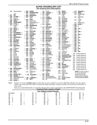
![Installation and Setup Guide
∗29 Menu Mode for IP and GSM Module Programming
This mode is for programming the Internet connection (IP) and optional GSM Module configuration,
collectively referred to as the Internal Device.
NOTE: The Internal Device is automatically set to address 3 and cannot be changed.
The following section describes the programming of the Internal Device using an alpha keypad.
Alternatively, these options can be programmed via the AlarmNet Direct website. After programming is
complete, the control must be registered with AlarmNet via the Internet connection. Refer to the
Registration with AlarmNet section for procedures.
IMPORTANT: The use of the IP connection or the VISTA-GSM module requires an AlarmNet–I account.
Please obtain the account information from the central station prior to programming this module.
Using an Alpha Keypad as a 7720P Programming Tool
When programming IP/GSM features (with ∗29
menu mode), the alpha keypad mimics the
functions of the 7720P Programming Tool. See
figure at right and table below for 7720P key
functions. Each key has two possible functions: a
normal function and a SHIFT function.
Normal functions: The numeric values labeled A B C
directly on the keys and the left-hand functions ARMED (A) BS/ESC 1 OFF 2 AWAY 3 STAY
D E F
shown in diagram on the ABC keys. To perform a READY (B) / 4 MAX 5 TEST 6 BYPASS
normal key function, simply press the desired key. S T X
SHIFT
(C) N/Y 7 INSTANT 8 CODE 9 CHIME
SHIFT functions: Those functions shown in FUNCTION SPACE ENTER
WHEN LIT (D) SHIFT READY 0 #
diagram above the numerical keys and the right-
hand functions shown on the ABC keys. To
perform a SHIFT key function, press SHIFT key 6160-7720P-001-V0
(D key), then press the desired function key (shift 7720P Emulation Template for Alpha Keypads
function is indicated by the lit READY LED).
Normal and SHIFT key Functions While in ∗29 Menu Mode
Key Normal Key Function SHIFT Key Function
(A) = BS/ESC [BS]: Press to delete entry [ESC]: Press to quit Program Mode
†
Also, can reset EEPROM defaults
(B) = ↓/↑ [↓]: Scroll down programming [↑]: Scroll up programming
(C) = N/Y [N]: Press for "NO" answer [Y]: Press SHIFT-Y for "YES" answer
(D) = SHIFT Press before pressing a SHIFT key function. Will light READY LED. LED goes out once a key is pressed. Press again
for each SHIFT function desired.
1/A [1]: For entering the number 1 [A]: Used for entering C.S. ID number
2/B [2]: For entering the number 2 [B]: Used for entering C.S. ID number
3/C [3]: For entering the number 3 [C]: Used for entering C.S. ID number
4/D [4]: For entering the number 4 [D]: Used for entering C.S. ID number
5/E [5]: For entering the number 5 [E]: Used for entering C.S. ID number
6/F [6]: For entering the number 6 [F]: Used for entering C.S. ID number
7/S [7]: For entering the number 7 [S]: Press to display diagnostic status
8/T [8]: For entering the number 8 [T]: Press to send TEST messages
9/X [9]: For entering the number 9 [X]: Press to reset the IP/GSM
[∗] / SPACE [∗]: Used to select programming options [SPACE]: Not used
0 [0]: For entering the number 0
[#] / ENTER [#] / ENTER: Press to accept entries No SHIFT function
† Active only when the "REVIEW?" prompt is displayed
5-18](https://image.slidesharecdn.com/honeywell-vista-21ip-install-guide-120804190306-phpapp02/85/Honeywell-Vista-21IP-Install-guide-60-320.jpg)
![Menu Mode Programming
Internal Device (Ip and GSM) Default Values
The programming default values for ∗29 Menu Mode are listed in the Table below.
OPTION STANDARD DEFAULT VALUE ACTUAL ENTRY
1 Internal Device IP
2 Primary City ID ??
3 Primary CS ID ??
4 Primary Sub ID ????
5 Supervision 24 Hours
6 GSM Rollover Y/N N (if GSM enabled)
7 GSM 24Hr Tst Y/N N (if GSM enabled)
8 Old Alarm Time 10 Minutes
9 IP Fault Time 00 Minutes
10 GSM Fault Time 00 Minutes (if GSM enabled)
11 Notify Panel Of Neither Fault (if IP and GSM enabled)
12 Use DHCP Y/N Y (if IP or IP/GSM enabled)
13 NIC IP Address 255.255.255.255 (if DHCP not used)
14 Subnet Mask 255.255.255.255 (if DHCP not used)
15 Gateway IP Addr 255.255.255.255 (if DHCP not used)
16 DNS IP Addr. 255.255.255.255 (if DHCP not used)
Status and Contact ID Reporting Codes
The Internal Device (IP/GSM) sends status messages to the control panel for network connectivity failures.
Trouble messages are displayed on the keypad as “Check 103,” with status displayed as “LngRng Radio”
followed by a 4-digit keypad display status code, defined below.
Keypad Display Status Codes Contact ID Codes (as displayed at 685) sent to CS via IP/GSM
CODE DESCRIPTION CODE DESCRIPTION
0000 Control panel lost communication with internal device E339 C803 Power-on reset
0005 internal device has lost contact with AlarmNet E350 C951 Primary communication path failure (Ethernet) **
000F internal device is not registered; account not activated R350 R951 Primary communication path restore (Ethernet) **
0019 GSM module shut down E350 C952 Secondary communication path failure (GSM) **
0400 internal device Power-on reset AND the control panel lost R350 C952 Secondary communication path restore (GSM) **
communications with IP/GSM E355 C000 Module lost ECP communication with control
R355 C000 Module restore ECP communication with control
E353 C103 Long range transmitter fault trouble
R353 C103 Long range transmitter fault restore
** reports only if IP and GSM enabled
Start ∗29 Menu Mode by pressing *29 while in Data Programming mode.
ENABLE IP/GSM? Enable INT IP/GSM?
0=No, 1=Yes
0 = no, not using either IP or GSM; 1 = yes using IP and/or GSM module; [∗] to continue
NOTE: Default = 1 (IP and/or GSM)
IMPORTANT: If using an external communication device, first follow the instructions in
the Inadequate Signal Strength paragraph in the VISTA-GSM Module Installation section
for physical installation of an external communication device. When complete, enter 1 at
this prompt and enter 1-Prog at the next prompt. Then program the external device using
the Installation and Setup Guide included with the external communication device.
1=PROG 2=DIAG Programming/Diagnostics Select
1= Prog (program the IP/GSM options)
0=QUIT
2 = Diag (enter diagnostic mode) NOTE: If using an external communicator, Diagnostic
mode option available only for communicators with firmware version 2.4.16 or higher.
0 = Quit; return to data field programming mode
Internal Device Programming Prompts
The keys used to select and enter options now follow 7720P keypad emulation. Refer to the table on the
previous page for detailed key functions. The following is a summary:
[∗] = scroll the options of a particular prompt
[#] = accept the entry and move to the next prompt
[A] = backspace or shift-[A} for escape
[B] = scroll to next prompt or shift-[B] scroll to previous prompt
[C] = answer No or shift-[C] answer Yes to prompt
[D] = shift key
5-19](https://image.slidesharecdn.com/honeywell-vista-21ip-install-guide-120804190306-phpapp02/85/Honeywell-Vista-21IP-Install-guide-61-320.jpg)
![Installation and Setup Guide
Internal Device Internal Device Selection
Disable – IP – GSM – IP & GSM
IP Select the desired type of internal device usage, IP and/or GSM (press [∗] to scroll choices).
Press [#] to continue
Multi mode Multi-Mode (email reporting)
Disabled = no email reporting of events
Disabled 4204 Sourced = up to four types of events reported (relay numbers 1-4 report as events 1-4
respectively)
2-4204 Sourced = up to eight types of events reported (first module’s relay numbers 1-4 report
as events 1-4 respectively; second module’s relay numbers 1-4 report as
events 5-8 respectively)
[#] to continue
Select the desired multi mode option (press [∗] to scroll choices).
This feature is available only after authorization for it is set via the web-based programming
tool on the AlarmNet Direct website.
Multi-mode emulates 4204 Relay Module outputs to send up to four (4204 sourced) or up to
eight (2-4204 sourced) reports of system events to the user via email (email address is
entered at the AlarmNet Direct website). Use the AlarmNet Direct website to customize
event titles, if desired. If enabled, a multi-mode address must be entered in the next prompt.
Use *79/*80 Menu modes to program each emulated relay output to trigger a desired system
event that, upon occurrence, will be sent to the user’s email address.
NOTES:
1. Multi-mode has not been evaluated by UL.
2. Multi-mode (email notification) is intended as a convenience for the user, and does not
replace Central Station reporting of critical events (alarms, troubles, etc.).
Multi mode Addr Multi-Mode Address
This prompt appears if Multi Mode is enabled.
(12) 12-15 =emulated 4204 Relay Module address.
Select the desired address. If using “2-4204-sourced,” the address of the second module is
automatically assigned an address one higher than the first module’s address.
NOTE: A 4204 Relay module address is required for multi-mode purposes, but an actual
4204 Relay module is not used.
Primary City ID Primary City ID
NOTE: Account information is provided by the central station administrator.
(??) 01-99 (decimal) = 2-digit primary city code
Primary CS ID Primary CS ID
01-FE (HEX)
(??) Enter the primary central station's system ID number,
Primary Sub ID Primary Subscriber ID
0001-9999 (decimal)
(????) Enter the 4-digit customer account number.
Remote AccessY/N Remote Access
(N)
This feature is available only after authorization for it is set via the web-based
programming tool on the AlarmNet Direct website.
[Y] = use remote services
[N] = do not use remote services
[#] to continue
Remote Services allow the end user to access their security system from their
computer via the remote services website. Most system functions can then be
performed.
5-20](https://image.slidesharecdn.com/honeywell-vista-21ip-install-guide-120804190306-phpapp02/85/Honeywell-Vista-21IP-Install-guide-62-320.jpg)
![Menu Mode Programming
K e yp a d A d d r e s s Keypad Address (for Remote Access)
This prompt appears if remote access is enabled.
(28) 1, 2, 5, 6 = emulated AUI address
17-23 = emulated standard keypad address
For enhanced remote access features, choose an AUI address. If no AUI addresses are
available (all four AUIs are being used), choose an available standard keypad address (some
remote access features will be unavailable).
NOTE: An AUI or standard keypad address is required for remote access purposes, but an
actual AUI device or keypad is not used.
Supervision Supervision
if using IP and/or GSM if using IP only (not for GSM usage)
24 Hours • 30 day • US UL Line (6 Min)
• 24-hours • US UL Line (90 Sec)
• None (no supervision) • CN UL Line Lv1 3 (3 Min)
• CN UL Line Lv1 4 (90 Sec)
• CN UL Line Lv1 5 (75 Sec)
• 1 hour
To scroll the choices: [∗] key scrolls forward; [backspace] key scrolls backward
[#] to continue
The supervising station must hear from the IP/GSM at least once during the supervision
period. AlarmNet transmits a communications failure alarm to the central station if the
supervision message is not received within the period.
This selection sets the supervision timing for one of the following values:
GSM Rollover Y/N GSM Rollover
Appears only if IP & GSM is selected as Internal Device option.
(N)
[Y] = all messages (including AlarmNet network supervisory messages) are sent over the GSM
network in the event of an Internet failure
[N] = all messages (except AlarmNet network supervisory messages) are sent automatically
over the GSM network in the event of an Internet failure
GSM 24Hr Tst Y/N GSM 24Hr Tst
N Appears only if IP & GSM is selected as Internal Device option.
[Y] = have a message sent once a day to verify GSM operation. A "secondary communication
path loss" message is generated if the message is not successfully delivered.
[N] = disable 24hr test
O l d A l a r m Ti m e Old Alarm Time
The old alarm time sets how long an undeliverable alarm is retried for delivery to
1 0 Mi n u t e s AlarmNet. If the message is not validated, it is retried until the old alarm time is reached
or the message is validated. The choices available are:
• 10 Minutes • 4 Hours
• 15 Minutes • 8 Hours
• 30 Minutes • 12 Hours
• 1 Hour • 24 Hours
• 2 Hours
To scroll the choices: [∗] key scrolls forward; [backspace] key scrolls backward
[#] to continue
I P F a u l t Ti m e IP Fault Time
Appears only if IP or IP & GSM is selected as Internal Device option.
(00 mins) 00-99 = time delay (in minutes) before the control notifies the central station that there is a loss
of contact with the network over the Ethernet (IP) connection.
0 = no delay (valid only If using IP only)
Must be two (2) minutes for UL installations.
G S M F l t Ti m e GSM Flt Time
Appears only if GSM or IP & GSM is selected as Internal Device option.
(00 mins) 00-99 = time delay (in minutes) before the control notifies the central station that a loss of
contact with AlarmNet network has occurred.
0 = no delay (valid only if using GSM only)
Must be two (2) minutes for UL installations.
5-21](https://image.slidesharecdn.com/honeywell-vista-21ip-install-guide-120804190306-phpapp02/85/Honeywell-Vista-21IP-Install-guide-63-320.jpg)
![Installation and Setup Guide
Notify Panel Of _ Notify Panel Of
Appears only if IP & GSM is selected as Internal Device option.
Neither Fault Select from the following choices:
• Neither Fault
• Both IP and GSM must fail before fault code is sent (status code 4005 displayed); panel
receives primary and secondary path failure messages. No message sent if only one or the
other path fails.
To scroll the choices: [∗] key scrolls forward; [backspace] key scrolls backward
• [#] to continue
NOTE: IP failure will always be sent to the central station as Primary Path Failure, and
GSM failure will always be sent as Secondary Path Failure.
IP address information prompts
The following prompts appear only if IP or IP & GSM is selected as Internal Device.
It is recommended to use dynamically allocated IP addresses, but if fixed IP addresses are desired, contact your
network administrator for the appropriate information.
NOTE: A valid IP address must be entered in each prompt before the system continues to the next prompt.
Entries cannot be left with the default values.
Use DHCP Y/ N Use DHCP
[Y] = have the IP addresses dynamically allocated (recommended), skip to Review prompt.
( Y) [N] = use fixed IP addresses; continue with next prompt
[#] to continue
NIC IP Address NIC IP Address
Enter the 4-part IP address for this device, separating each part with a space ([∗] key,
255.255.255.255
displayed as periods).
[#] to continue
Subnet Mask Subnet Mask
Enter the 32-bit address mask used to indicate the portion (bits) of the IP address that is
255.255.255.255
being used for the subnet address, separating each part with a space ([∗] key, displayed as
periods).
[#] to continue
G a t e wa y I P A d d r Gateway IP Addr
Enter the 4-part IP address assigned to the Gateway, separating each part with a space
255.255.255.255
([∗] key, displayed as periods). If unused set to 0.0.0.0.
[#] to continue
DNS IP Addr DNS IP Addr
Enter the 4-part IP address assigned to the DNS (Domain Name System) server,
255.255.255.255
separating each part with a space ([∗] key, displayed as periods). If unused set to 0.0.0.0.
[#] to continue
Review? Y/ N Review (and Exit ∗29 Menu mode or Reset Defaults)
You can review the ∗29 Menu mode options to ensure that the correct responses have been
made. When satisfied with entries, select [N] to exit ∗29 Menu mode.
To review prompts or exit ∗29 Menu mode:
[Y] = review prompts and entries, starting with Internal Device. Use the up/down arrow keys to
scroll through the program fields without changing any of the values. If a value requires
change, simply type in the correct value. When the last field is displayed, the “REVIEW?”
prompt again appears.
[N] = Exit *29 menu mode and return to data field programming mode. The prompt briefly
displays “DONE” before returning to data field mode prompt “Enter ∗ or #.”
[#] to accept Y or N selection (# alone exits same as N)
To reset ∗29 Menu mode defaults:
Press [ESC] at the Review prompt to display the “Reset Factory Defaults” prompt.
[Y] = reset ∗29 menu mode options to factory values; if selected, all programmed ∗29 Menu
mode options are reset to the factory settings
[N] = cancel reset defaults function
5-22](https://image.slidesharecdn.com/honeywell-vista-21ip-install-guide-120804190306-phpapp02/85/Honeywell-Vista-21IP-Install-guide-64-320.jpg)
![Menu Mode Programming
Programming IP/GSM Options via AlarmNet Direct Website
To program the IP/GSM options via the AlarmNet Direct website (if you are already signed up for this
service), go to: https://services.alarmnet.com/AlarmNetDirect/userlogin.aspx
If you are not signed up for this service, click on “Dealer Sign-Up.
Log in and follow the on-screen prompts.
Please have the following information available:
1. Primary City ID (two-digit number)
2. Primary Central Station ID (two-digit hexadecimal number)
3. Primary Subscriber ID (four-digit number)
4. MAC ID and MAC CRC number (located on the outside of box and on label inside module) or MIN number
of the device you are replacing
5. Mode of operation of existing module if replacing a "C" series radio.
After programming is complete, you must transfer the data to the module and the module must be registered.
Refer to the Registration section for details.
∗
IP/GSM Diagnostic Commands (∗29 Menu Mode)
Diagnostic commands can be used to quickly view your Internet and GSM connectivity settings and options.
For each command (except [↓] and [0]) press the [shift] key and then the designated command key. For
example, press [shift] then [1/A] to display the software revision screen.
To enter Diagnostic mode:
1. Press ∗29 while in data field programming mode.
2. Enter “1” at the “Enable IP/GSM” prompt then press [∗].
3. Select “2” (Diag) at the next prompt.
4. Enter the desired command at the “Sel Key Command” prompt.
For subsequent commands, enter the next command at the currently displayed screen.
To exit Diagnostic mode, press ESC (shift-[A]).
Key Prompt Function Key Prompt Function
Software Revision [D] Physical Link Physical Link
[A] INTERNAL IP/GSM "x.x.xx" indicates the Good/Bad Only if IP or IP/GSM
x.x.xx mm/dd/yy installed software enabled. Indicates whether
Revision. Mm/dd/yy the device has detected a
indicates month, day and physical connection to the
year of the revision. internet. [∗] to continue to
MAC, SCID, IMEI NIC IP address.
[B] MAC xxxxxxxxxxxx
MAC CRC yyyy “xxxxxxxxxxxx” indicates NIC IP Address IP Information Displays
the IP/GSM’s unique xxx.xxx.xxx.xxx Displays the IP address
identification number. assigned to this device.
Yyyy indicates the 4 digit [∗] to go to subnet mask.
MAC CRC needed to enroll Displays the 32-bit address
the device in dealer direct. Subnet Mask
xxx.xxx.xxx.xxx mask used to indicate the
[∗] to go to SCID. portion (bits) of the IP
SCID xxxxx xxxxx Only if GSM or IP/GSM Address that is being used
xxxxx xxxxx enabled. Displays the for the subnet address.
identification number [∗] to go to gateway IP.
assigned to the SIM card Displays the IP Address
(SCID) in this device. Gateway IP Addr
xxx.xxx.xxx.xxx assigned to the Gateway.
[∗] to go to IMEI. [∗] to go to DNS server IP.
IMEI xxxxxxxx Only if GSM or IP/GSM Displays the IP Address
enabled. Displays the DNS Serv IP
Xxxxxx x xxx.xxx.xxx.xxx assigned to the DNS
identification number (Domain Name System)
assigned to the GSM server.
module in this device. [∗] to go to encryption test.
[∗] returns to MAC.
Encryption Test Performs a self-test of the
[C] Mon 01 Jan 2006 Time AES encryption algorithm.
AES Passed!
05:48:39 am Retrieves the current date [∗] to go to DHCP.
and time from the
AlarmNet network in DHCP (Dynamic Host
Greenwich Mean Time DHCP Configuration Protocol)
OK indicates server is okay.
(GMT). This display
confirms that the module [∗] returns to Physical Link
is in sync with network. prompt.
5-23](https://image.slidesharecdn.com/honeywell-vista-21ip-install-guide-120804190306-phpapp02/85/Honeywell-Vista-21IP-Install-guide-65-320.jpg)
![Installation and Setup Guide
IP/GSM Diagnostic Commands (continued)
Key Prompt Function
[E] GSM Status Displays
PriRSSI GPRS REG Only if GSM or IP/GSM [S] Status request
-xxxdbm x x enabled. FLT OK = normal
PriRSSI – Primary Site OK i = IP off line
RSSI level in dbm I = IP fault reported
GPRS – GPRS Service g = GSM off line
availability where “x” can G = GSM fault reported
be: Test Alarm
[T]
“Y” if GPRS is available Test Msg Sent Sends a Test alarm to
“N” if GPRS not available AlarmNet. Functional for a
REG – Registration status registered IP/GSM only. If
from GSM module where the device is not
“x” can be: registered, a message is
N – Not Registered displayed indicating that
H – Registered Home the command cannot be
S – Searching executed.
D – Registration Denied
R – Registered Roaming [X]
? – Unknown Reg. State Reset CPU Y/N Reset the IP/GSM.
[∗] to continue to next [N] = return to diagnostic
screen. mode (blank screen =
Cntry – Country Code enter next command
Cntry Netw LAC Netw – Network Code or escape).
xxx xxx xxxxx LAC – Reg. status from [Y] = resets the module
GSM. (blank screen = when
[∗] to continue to next reset complete, enter
screen. next command or
escape).
Cell – Base Station ID
Cell BaseSt Chan BaseSt – Base Station
Xxxxx x xxx ↑
[↑] Registering … Registration
Antenna Sector
Chan – Control Channel
(Shift-UP arrow)
Registers a programmed
in use
IP/GSM with AlarmNet. If
[∗] to continue to next
it is configured to report to
screen.
AlarmNet, the IP/GSM will
Secondary GSM Site RSSI register with AlarmNet.
Second Site RSSI level in dbm.
-xxxdbm [∗] to continue to next
screen. ↓
[↓] Enter PIN# Registration with PIN
for Replacement
[F] Network Diagnostic Module (DN arrow)
Testing Gateway Test
Redir 1 Registers a programmed
Only if IP or IP/GSM
IP/GSM with AlarmNet if
enabled.
it is configured to report to
Performs a set of network
AlarmNet.
diagnostics that tests the
integrity of the links
between the IP/GSM and [0] Force Upload of
Force Server Update
the various connection Y/N Configuration File to
points (Redirs) to Server
AlarmNet. [Y] = force the device to
upload its entire
configuration file to the
server.
[N] = cancel the operation.
NOTE: If the internet is
not available, and the
module is not initialized
when you enter this
command, the following
screen will be displayed:
Cannot Upload
Try Later! _
Wait for the RSSI LEDs to
light, indicating the
module has completed its
initialization, and try
again.
5-24](https://image.slidesharecdn.com/honeywell-vista-21ip-install-guide-120804190306-phpapp02/85/Honeywell-Vista-21IP-Install-guide-66-320.jpg)
![Registering the Control with AlarmNet
The control must be registered with AlarmNet before internet communication (via IP or GSM) can occur.
To register, the control must be connected to the Internet.
Register the control by using one of these methods:
Register by phone
1. Call 1-800-222-6525
You will need the following information:
• MAC ID and MAC CRC number (found on the label)
• Subscriber information (provided by the central station), including a city code, CSID, and a
subscriber ID
• Activation ID (AID) and AID CRC numbers (found on the module’s label or on its carton)
2. When instructed to do so, triple-click the Test switch to complete the registration.
Register with AlarmNet Direct Website
To register via AlarmNet Direct Website, please go to:
https://services.alarmnet.com/AlarmNetDirect/userlogin.aspx.
Log in and follow the on-screen prompts. Please have the following information available:
• Primary City ID (two-digit number provided by central station)
• Primary Central Station ID (two-digit hexadecimal number provided by central station)
• Primary Subscriber ID (four-digit number provided by central station)
• MAC ID and MAC CRC number (located on outside of box and on label on control’s PC board)
• Activation ID (AID) and AID CRC numbers (found on the module’s label or on its carton)
If you are not signed up for this service, click on “Dealer Signup” from the login screen to gain access to the
Honeywell web-based programming.
Dealer Sign-Up Direct Link: https://services.alarmnet.com/AlarmNetDirectP_Sign-Up.
You will be instructed how to proceed upon completing the sign-up form. Only one sign-up per dealer is
required. Once an initial user is established, additional logins may be created by that user.
Once the control is registered, you may log out of the AlarmNet Direct website.
Register with Alpha Keypad using *29 Menu mode
1. Enter *29 Menu mode, select Diagnostic mode, then press Shift then [↑] key (D key followed by the B
key). The registration message is sent (“Registering” displayed) and the control waits for the
acknowledgment.
2. “Registration SUCCESS” displayed, indicating successful registration.
Register with Test Switch on control’s PCB (triple-click)
1. Click the switch three times.
2. Watch the GSM Status LEDs: The Message (yellow) LED and the Status (green) LED will blink slowly
in unison while registration is in progress.
3. When registration is complete, the Status (green) LED goes out.
Upload/Download via the Internet
This control supports upload/download programming capability via the Internet by using the AlarmNet
network and Compass downloading software. The control must be connected to the Internet (via the on-board
RJ45 connector or VISTA-GSM module), have all IP features programmed (∗29 Menu mode), and be registered
with AlarmNet. The following is required at the Downloading Office:
• Broadband Internet Access and Broadband (Cable/DSL) Modem
• Broadband (Cable/DSL) Router (optional, if connecting more than one device to the Internet)
• Computer running Compass Downloading Software version that supports Internet upload/download for this
control.
To perform upload/download functions:
1. Connect the computer to the Internet and start the Compass downloading software.
2. Open the control’s account, then select the Communications function and click the Connect button.
3. At the Connect screen, check that the control’s MAC address is entered and the TCP/IP checkbox is checked.
4. Click Connect. The Internet connection to the control is made automatically via AlarmNet.
5. Once connected, use the Compass downloading software as normal to perform upload/download functions.
5-25](https://image.slidesharecdn.com/honeywell-vista-21ip-install-guide-120804190306-phpapp02/85/Honeywell-Vista-21IP-Install-guide-67-320.jpg)
![Installation and Setup Guide
Programming Installer and User Schedules
The system provides up to 32 schedules, which can be used to automatically control 11 types of system events
at pre-defined times. Some events are reserved for the installer only.
There are 16 schedules for use by the end-user, 16 for use by the installer.
NOTES:
• The master code can only access schedules 01-16 and events 00-07.
• System clock must be set before schedules can be used.
• Programmed schedules do not take effect until the next scheduled “start” time. (e.g., if programming a
schedule time window for 8AM to 5PM, the schedule does not take effect until 8AM after the schedule has
been programmed.)
Start Scheduling mode by entering installer code + [#] + [6] [4] while in normal operating mode.
ENTER SCHED NO. Schedule Number
01-16 = end-user schedules
00=QUIT 00
17-32 = installer-only schedules
[∗] to continue
Enter the desired schedule number.
ENTER EVENT Enter Event
00 = clear event 05 = Forced Away Arming†
01 = Relay On/Off 06 = Auto Disarm
02 = User Access 07 = Display “Reminder”
NOTE: Events 07 and 03 = Latch Key Report to Pager 10 = Display custom words ††
10 cause the keypad to 04 = Forced Stay Arming† 11 = Periodic Test Report†††
beep every 30 seconds Press [∗] to continue
when messages are Enter the desired event number for event you want to occur at a specified time.
displayed. Stop the
Events 10-11 are reserved for the installer only.
beeps by pressing any
key. Latch key report (option 03) is sent to all pagers in the user’s partition and is active only
when the system is armed (message sent is 777-7777). User must be enabled for paging
(see User Attributes in System Operation section).
† Forced bypass is automatically enabled regardless of setting in field *23.
†† If selected, system displays custom words 8, 9, and 10 at defined time. Can be used as
installer’s reminder message to the end user.
††† See key commands in Testing the System section to quickly set periodic test
reporting intervals.
DEVICE NUMBER Device Number (For event 01-relay on/off)
XX
01-18 = device number; press [∗] to continue
Enter the physical device number as programmed in ∗79 Menu Mode, then press [*] to
continue to the “Start” prompt.
Device numbers 17 and 18 designate built-in triggers 1 and 2 respectively.
GROUP NUMBER Group Number (For event 02-user access)
X
1-8 = group number; press [∗] to continue to the “Start” prompt
PARTITION Partition (For events 03-07, 10)
0 = all partitions; 1 = partition 1; 2 = partition 2; 3 = common
X
Press [*] to continue to the “Start” prompt.
START SMTW TFS Start Time
01-12 = hour; 00-59 = minute; 0 = AM; 1 = PM; Days = place “1” under days
HH MMA M 0 0 1 0 0 0 0
Press [∗] to continue.
Enter the event’s start time and days of the week to occur.
To select days, position the cursor under the desired days using the [∗] key to move
forward, then press “1” to select the day.
5-26](https://image.slidesharecdn.com/honeywell-vista-21ip-install-guide-120804190306-phpapp02/85/Honeywell-Vista-21IP-Install-guide-68-320.jpg)
![Menu Mode Programming
STOP SMTW TFS Stop Time (For events 01-relay on/off; 02-user access; 03-latch key report)
01-12 = hour; 00-59 = minute; 0 = AM; 1 = PM; Days = place “1” under days
HH MMA M 0 0 1 0 0 0 0
Press [∗] to continue.
Enter the event’s stop time and days of the week to occur.
To select days, position the cursor under the desired days using the [∗] key to move
forward, then press “1” to select the day.
REPEAT OPTION Repeat Option
0-4 X
0 = do not repeat; 1 = repeat weekly; 2 = repeat biweekly (every other week)
3 = repeat every third week; 4 = repeat every fourth week
Press [∗] to continue.
Enter the desired repeat option for this schedule.
e.g., To make a schedule that happens everyday you would select all days with a repeat
count of 1. To make a schedule that runs for one week then stops, select everyday with a
repeat count of 0.
RANDOMIZE Randomize (For events 01 and 11)
0=NO 1=YES X
0 = no; 1 = yes
Press [∗] to continue.
If selected, the scheduled start and stop times will vary within 60 minutes of the “hour”
time. For example, if a schedule is set to start at 6:15pm, it will do so the first time 6:15pm
arrives, but on subsequent days it will start anytime between 6:00 and 6:59 p.m.
NOTE: Do not use the random option if the start and stop times are within the same “hour”
setting, otherwise unpredictable results may occur (e.g., the randomized stop time may occur
before the start time).
5-27](https://image.slidesharecdn.com/honeywell-vista-21ip-install-guide-120804190306-phpapp02/85/Honeywell-Vista-21IP-Install-guide-69-320.jpg)
![Installation and Setup Guide
AVS System Enable and Quick Programming Commands
Applies to an AVS system using an ECP connection to the control.
1. Install the AVS module according to its instructions.
2. Use one of the control’s AVS Quick Program commands as follows (see Quick Program Command Results below for
results of each command):
• installer code + [#] + 0 + 3: enable AVS operation without panel sounds on the AVST speaker
• installer code + [#] + 0 + 4: enable AVS operation and enable panel sounds on the AVST speaker
3. Use data field ∗55 Dynamic Signaling Priority to enable the reporting path for AAV communication.
4. To undo the Quick Command programming, use the following commands:
• installer code + [#] + 0 + 5: remove all options set by [#] + 03 quick command
• installer code + [#] + 0 + 6: remove all options set by [#] + 04 quick command
Quick Program Command Results
When either the #03 or #04 Quick Program command is used, the following are automatically programmed and no longer
available for other control panel purposes.
Pre-Programmed #03 Command #04 Command
Output Function 46 (zone type 60, relay 15) Same as #03 plus:
No. 47 (zone type 61, relay 16) 41 (zone type 14, relay 13)
(∗80 mode) 48 (zone type 62, relay 16) 42 (zone type 22, relay 13)
43 (zone type 39, relay 14)
44 (zone type 33, relay 14)
45 (zone type 22, relay 14
Output Relay No. 15 (addr 11, relay pos 2) Same as #03 plus:
(∗79 mode) 16 (addr 11, relay pos 1) 13 (addr 11, relay pos 4)
14 (addr 11, relay pos 3)
Protection Zone 4229 zn 48 (zt 81, addr 11) Same as #03 command
(∗56/∗58 mode)
Device Address address 11 (AVS module) Same as #03 command
Data Field ∗91 AAV enabled AAV enabled
5-28](https://image.slidesharecdn.com/honeywell-vista-21ip-install-guide-120804190306-phpapp02/85/Honeywell-Vista-21IP-Install-guide-70-320.jpg)
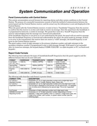
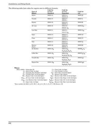
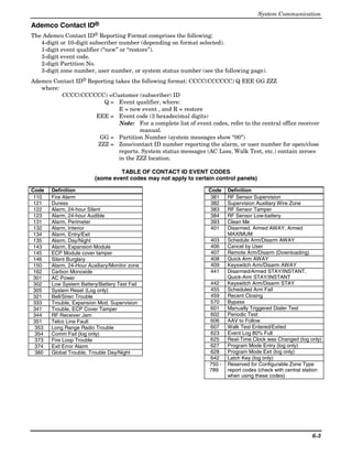
![Installation and Setup Guide
System Security Codes
The systems provides one Installer code, one System Master code, plus a set of other user codes intended for
other users of the system. These codes can each be assigned one of 5 authority levels, which determine the
functions each code can perform as listed in the table below.
Number of Codes: Provides 48 security codes (plus Installer code), including one System Master code, two
Partition Master codes, and 45 general user codes.
Authority Levels (can be assigned to users 03-49 only; users 1 and 2 cannot be changed)
Level User No. Functions
Installer 01 (default=4112) perform all security functions except can disarm only if used to arm; can
enter program mode; can change System Master code; cannot assign any other user
codes
System 02 (default 1234) only one system master code per system; can perform all security
Master functions, add/delete users in either partition, change system master code, view event
log, set system clock, program keypad macro, program scheduled events, activate output
devices (triggers/relays)
Partition P1 = 03 Same as Master, except add/delete users limited to assigned partition only, (these
Master P2 = 33 users can be assigned different authority levels, if desired; any user can be assigned
(default) the partition master authority level)
0-User 03-49 perform security functions (arm, disarm, etc.) only; cannot add/delete users, view event
log, set system clock or program scheduled events
1-Arm Only see “user” arm system only
2-Guest see “user” can disarm the system only if it was used to arm the system
3-Duress see “user” performs security functions, but also silently sends a duress message to the central
station; reports as duress code user number.
4-Partition see “user” See Partition Master paragraph above; used to assign other user numbers as partition
Master masters
Refer to the user guide for detailed procedures on adding/deleting security codes and changing user
attributes.
The following is a brief description of how to add user codes.
Changing the System Master code...
Using Installer code: Installer code + [8] + 02 + new code
Using current System Master code: System Master code + [8] + 02 + new code + new code again
Adding a User Code: Master code + [8] + 2-digit user no. + user’s code
Deleting a User Code: Master code + [8] + 2-digit user no. + [#] [0]
Assigning Attributes: Master code + [8] + 2-digit user no. + [#] [attribute no.] + value
Attributes: Values
1 = Authority Level 0-4 (see Authority Level table above)
2 = Access Group 0-8 (0 = not assigned to a group)
3 = Active Partition(s) 1, 2, 3 (common)
for this user; Enter partitions consecutively if more than one and press [#] to
end the entries.
4 = RF Zone No. Assigns user number to button type zone for arm/disarm (keyfob
must be enrolled in system first; see Wireless Key
Templates section).
5 = Open/Close Paging 1 for yes, 0 for no
6-4](https://image.slidesharecdn.com/honeywell-vista-21ip-install-guide-120804190306-phpapp02/85/Honeywell-Vista-21IP-Install-guide-74-320.jpg)
![System Operation
Keypad Functions
The following is a brief list of system commands. For detailed information concerning system functions, refer
to the User's Manual. For Touch Screen style keypad users, refer to the separate Touch Screen keypad (AUI)
User’s Guide.
Voice Keypads
The 6150V/6160V Voice Keypads provide the following features:
• Message Center, which lets the user record and playback one message.
• Voice Status, which can announce system status by using the STATUS key.
• Voice Chime, which can alert users to the opening of doors/windows while the system is disarmed.
Refer to the User Guide for specific procedures for activating and using these features.
Keypad Commands
Function Description
Silence Burglary Pressing any key will silence the keypad sounder for 10 seconds. Disarming the system will
Alarms silence both keypad and external sounders.
Silence Fire or Carbon Press the OFF [1] key to silence the keypad sounder and, for fire alarms, the external
Monoxide Alarms sounder. The detector sounding stops when the contaminated air is cleared from the
detector; see the detector’s instructions for further information.
Quick Arm If enabled (field ∗21), you can press [#] in place of the system's security code, plus the
desired arming key (Away, Stay, Instant, Maximum)
Single-Button arming If programmed (*57 Function Key menu mode), lettered keys A-D can be used for arming,
using options 3-AWAY, 4-STAY, 5-NIGHT-STAY, or 6-Step-Arming
If used, no security code is required to arm the system.
Alarm Memory When the system is disarmed, any zones that were in an alarm condition during the armed
period will be displayed. To clear this display, simply repeat the disarm sequence (enter
the security code and press the OFF key) again.
Arming Away Enter code + AWAY [2] or simply press appropriate lettered key on the keypads (see
“Single-Button Arming” above). If the “Auto-Stay Arm” feature is enabled (field *84) and
the entry/exit door is not opened and closed within the programmed exit delay time, the
system will automatically arm in STAY mode if armed from a wired keypad (non-RF
device). If the door is opened and closed within the exit delay period, the system arms in
AWAY mode.
Arming Stay Enter code + STAY [3] or simply press appropriate key on the keypads (see “Single-Button
Arming” above). See “Arming Away” above for Auto-Stay arming feature.
Arming Night-Stay Enter code + STAY [3] + STAY [3] or simply press appropriate key on the keypads (see
“Single-Button Arming” above).
Arming Instant Enter code + INSTANT [7].
Arming Maximum Enter code + MAXIMUM [4] or simply press appropriate lettered key on the keypads (see
“Single-Button Arming” above).
Disarming Enter code + OFF [1]. If entry delay or an alarm is active, you do not need to press
OFF.
Bypassing Zones Enter code + BYPASS [6] + zone number(s).
Forced (Quick) Bypass To automatically bypass all faulted zones, use the “Quick Bypass” method. Enter code +
BYPASS + [#], then wait for all open zones to be displayed. Arm when display indicates
“ZONE BYPASSED” and “READY TO ARM”.
Chime Mode Enter code + CHIME [9]. To turn chime off, enter code + CHIME again.
Activate Output If relay outputs (via a 4204, or 4229), or Powerline Carrier devices are used, two keypad
Devices entries available to the user are included. If programmed, these entries can be used to
manually activate or deactivate the device(s) for starting or stopping some action, such as
turning lights on or off, etc. These keypad entries are:
[Security Code] + # + 7 + [2-digit Device #] activates (starts) that device.
[Security Code] + # + 8 + [2-digit Device #] deactivates (stops) that device.
6-5](https://image.slidesharecdn.com/honeywell-vista-21ip-install-guide-120804190306-phpapp02/85/Honeywell-Vista-21IP-Install-guide-75-320.jpg)
![Installation and Setup Guide
SUMMARY OF ARMING MODES
Arming Mode Features for Each Arming Mode
Exit Delay Entry Delay Perimeter Armed Interior Armed
AWAY Yes Yes Yes Yes
STAY Yes Yes Yes No
NIGHT-STAY Yes Yes Yes only those zones
listed in Night-
Stay zone list
INSTANT Yes No Yes No
MAXIMUM Yes No Yes Yes
Panic Keys
There are three Panic keys (A, B, and C) that, if programmed, can be used to manually initiate alarms and
send a report to the central station.
Each key can be programmed for 24-hour Silent, 24-hour Audible, Fire, or Personal Emergency responses.
The programmed Panic response is activated when the appropriate key is pressed for at least 2 seconds.
The Panic keys are identified by the system as follows:
Keys Displayed as Zone
∗
[A] (∗/1) 95
∗
[B] (∗/#) 99
[C] (3/#) 96
IMPORTANT: For a Silent panic function (if programmed) to be of practical value, you must program a
report code for the zone and the system must be connected to a central station.
Setting the Real-Time Clock
NOTE: All partitions must be disarmed before date/time can be set.
Set the time and date by doing the following:
1. +[#] + [6] [3] Alpha Display:
(Master Code) DISARMED
READY TO ARM
2. Press [∗] when the time/date is displayed.
TIME/DATE SAT
A cursor appears under the first digit of the hour.
04:04PM 10/17/00
To move cursor ahead, press [∗]. To go back, press [#].
Current time display
• Enter the 2-digit hour setting.
• Enter the 2-digit minute setting.
TIME/DATE SAT
• Press [1] for PM or [2] for AM.
04:04P2000/10/17
• Enter the last two digits of the current year. Time/date editing display
• Enter the 2-digit month setting.
• Enter the 2-digit day setting.
3. To exit, press [∗] when cursor is at the last digit, or wait 30 seconds.
6-6](https://image.slidesharecdn.com/honeywell-vista-21ip-install-guide-120804190306-phpapp02/85/Honeywell-Vista-21IP-Install-guide-76-320.jpg)
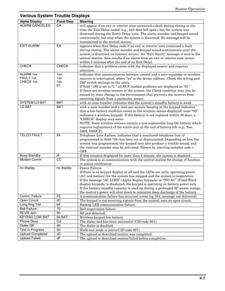

![S E C T I O N 7
Testing the System
About Test Procedures
After the installation is complete, you should perform the following tests:
System Test: Checks that all zones have been installed properly and the system responds to faults.
Dialer Test: Checks that the phone connection to the central station is working properly.
Go/No Go Test: Checks that transmissions can be received from transmitters. Should be performed
before permanently mounting transmitters.
RF Sniffer Mode: Checks that RF transmitter serial numbers have been properly enrolled.
Battery Tests: Automatic battery tests are performed by the system.
System Test
NOTE: Test mode can be entered from any keypad. However, faulted zones appear only on those keypads
assigned to the partition to which the zone is assigned (i.e., partition 1 zones appear only on partition 1
keypads, etc.). To see another partition’s faulted zones, view a keypad assigned to that partition or use the
GOTO command (code +[∗] + partition number 0-3, where 0 is the keypad’s home partition).
With the system in the disarmed state, check that all zones are intact (not faulted). Doors and windows with
contacts should be closed, PIRs should be covered (use a cloth to mask them temporarily if necessary). If a
“NOT READY” message is displayed, press [∗] to display the faulted zone(s). Restore faulted zone(s) if
necessary, so that the “READY” message is displayed.
1. Enter Installer Code + 5 [TEST] , then press “0” at the prompt to start Walk Test mode.
1=DIAL, 0=WALK (no special display on Fixed-Word keypads)
The following will be displayed on the initiating keypad and a Contact ID report will be sent (code 607):
TEST IN PROGRESS (“dd” displayed on Fixed-Word Display Keypads)
2. Upon entering the system test mode, the outside sounder should sound for 1 second.
If the backup battery is discharged or missing, the sounder may not turn on and a “LOW BATTERY”
report will be transmitted with a “TEST” report.
The keypad will beep about every 30 seconds as a reminder that the system is in the Test mode.
NOTE: Wireless motion detectors (Passive Infrared units) will send signals out only if they have been
inactive for 3 minutes (conserves battery life).
3. Test all sensors using the procedure described in the User’s Guide “Testing the System” section.
4. After checking sensors, turn off the test mode by entering installer code + OFF.
NOTE: Test mode automatically ends after 4 hours. During the final 5 minutes (after 3 hours 55
minutes of Test mode), the keypad emits a double-beep every 30 seconds to alert that the end of Test
mode is nearing.
Checking Transmitter Enrollment (Sniffer Mode)
Use this mode to verify that all transmitters have been properly programmed. Make sure both partitions are
disarmed before trying to enter this mode, since this is a system-wide command.
1. From a keypad in partition 1, press [Installer code] + [#] + 3.
(sniffer mode can be started only from partition 1)
NOTE: If the communicator is in the process of sending a report to the central station, the system will
not go into the Sniffer mode. If so, wait a few minutes, and try again.
The keypads in both partitions will display all zone numbers of wireless units (in both partitions)
programmed into the system. Fault each transmitter in turn, causing each one to send a signal. As the
system receives a signal from each of the transmitters, the zone number of that transmitter disappears
from the display.
2. After all transmitters have been checked, exit the sniffer mode by keying [Installer code] + OFF.
IMPORTANT: Sniffer mode does not automatically expire. You must manually exit Sniffer mode (by
entering [Installer code] + OFF) to return to normal operation.
7-1](https://image.slidesharecdn.com/honeywell-vista-21ip-install-guide-120804190306-phpapp02/85/Honeywell-Vista-21IP-Install-guide-79-320.jpg)
![Installation and Setup Guide
NOTES: • All BR type units must physically be activated to clear the display.
• When one button of a transmitter (RF, UR, or BR) is activated, all zones assigned to other
buttons on that transmitter are cleared from the display. This also applies to 5816 and 5817
transmitters, which have multiple loops (zones).
• Any transmitter that is not “enrolled” will not turn off its zone number.
Go/No Go Test Mode
The Go/No Go Test verifies adequate RF signal strength from the proposed transmitter location, and allow
you to reorient or relocate transmitters if necessary, before mounting the transmitters permanently. This
mode is similar to the Transmitter Test mode, except that the wireless receiver gain is reduced. This will
enable you to make sure that the RF signal from each transmitter is received with sufficient signal
amplitude when the system is in the normal operating mode.
1. Enter [Installer code] + [#] + 4 from the partition being tested. For multi-partition systems, repeat this
test for each partition.
2. After you have placed transmitters in their desired locations and the approximate length of wire to be run
to sensors is connected to the transmitter's screw terminals (if used), fault each transmitter. Do not
conduct this test with your hand wrapped around the transmitter, as this will cause inaccurate results.
a. The keypad will beep three times to indicate signal reception and display the zone number.
b. If the keypad does not beep, you should reorient or move the transmitter to another location. Usually
a few inches in either direction is all that is required.
4. If each transmitter produces the proper keypad response when it is faulted, you can then permanently
mount each of the transmitters according to the instructions provided with them.
5. Exit the Go/No Go Test mode by entering: [any user code (partition-specific)] + OFF.
Dialer Communication Test and Periodic Test Reports
1. Enter Installer Code + 5 [TEST], then press “1” at the prompt to start the Dialer Test (checks phone line
integrity only; does not confirm report transmissions).
1=DIAL, 0=WALK (no special display on Fixed-Word keypads)
The keypad beeps twice and displays the following if test is successful:
PHONE OKAY (“Cd” displayed on Fixed-Word Display Keypads)
A Contact ID report will also be sent (code 601)
If the dialer test is unsuccessful, “COMM FAILURE” (or FC) is displayed.
2. Enter Installer code + OFF to clear the display and exit.
Automatic Periodic Test Report
The system can be set to automatically send test reports (enabled in field *64; Contact ID code 602) at
specified intervals. Frequency of the reports is set in Scheduling mode (event 11) or by the following key
commands: installer code + [#] + 0 + 0 = test report sent every 24 hours
installer code + [#] + 0 + 1 = test report sent once per week
installer code + [#] + 0 + 2 = test report sent every 28 days
Each mode sets schedule 32 to the selected repeat option; the first test report is sent 12 hours after command.
To ensure that test reports are sent at the times expected, set the Real-Time Clock to the proper time before
entering the test report schedule command.
Automatic Standby Battery Tests
1. An automatic test is conducted every 3 minutes to ensure that a standby battery is present and properly
connected. If a battery is not present or is not properly connected, a “LOW BATTERY” message is
displayed and, if so programmed, will be reported to the central station.
2. A battery capacity test is automatically conducted for 2 minutes every 4 hours, beginning 4 hours after
exiting the Programming mode or after powering up the system. In addition, entry into the Test mode
will also cause a battery capacity test to be initiated. If the battery cannot sustain a load, a “Low
Battery” message is displayed and, if so programmed, will be reported to the central station.
7-2](https://image.slidesharecdn.com/honeywell-vista-21ip-install-guide-120804190306-phpapp02/85/Honeywell-Vista-21IP-Install-guide-80-320.jpg)


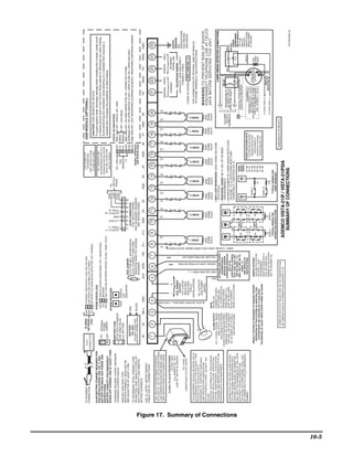


The document is an installation and setup guide for the Ademco Vista-21IP/Vista-21IP SIA security systems, providing key recommendations for fire and burglary detection device placement based on NFPA standards. It details the system features, installation highlights, and programming procedures, including guidelines for smoke and heat detectors and intrusion protection measures. Additionally, the guide outlines the various components, compatible devices, and testing protocols necessary for effective system operation.


![Fire alarm system_nec_september[1]](https://cdn.slidesharecdn.com/ss_thumbnails/firealarmsystemnecseptember1-140206154711-phpapp02-thumbnail.jpg?width=640&height=640&fit=bounds)


