SlideShare a Scribd company logo
1 of 4
Download to read offline
www.metrixvibration.com • info@metrixvibration.com • 281.940.1802
Doc# 1004461 • June 2019-Rev W• Page 1 of 4
5550 & 5550G Mechanical Vibration Switches
Datasheet
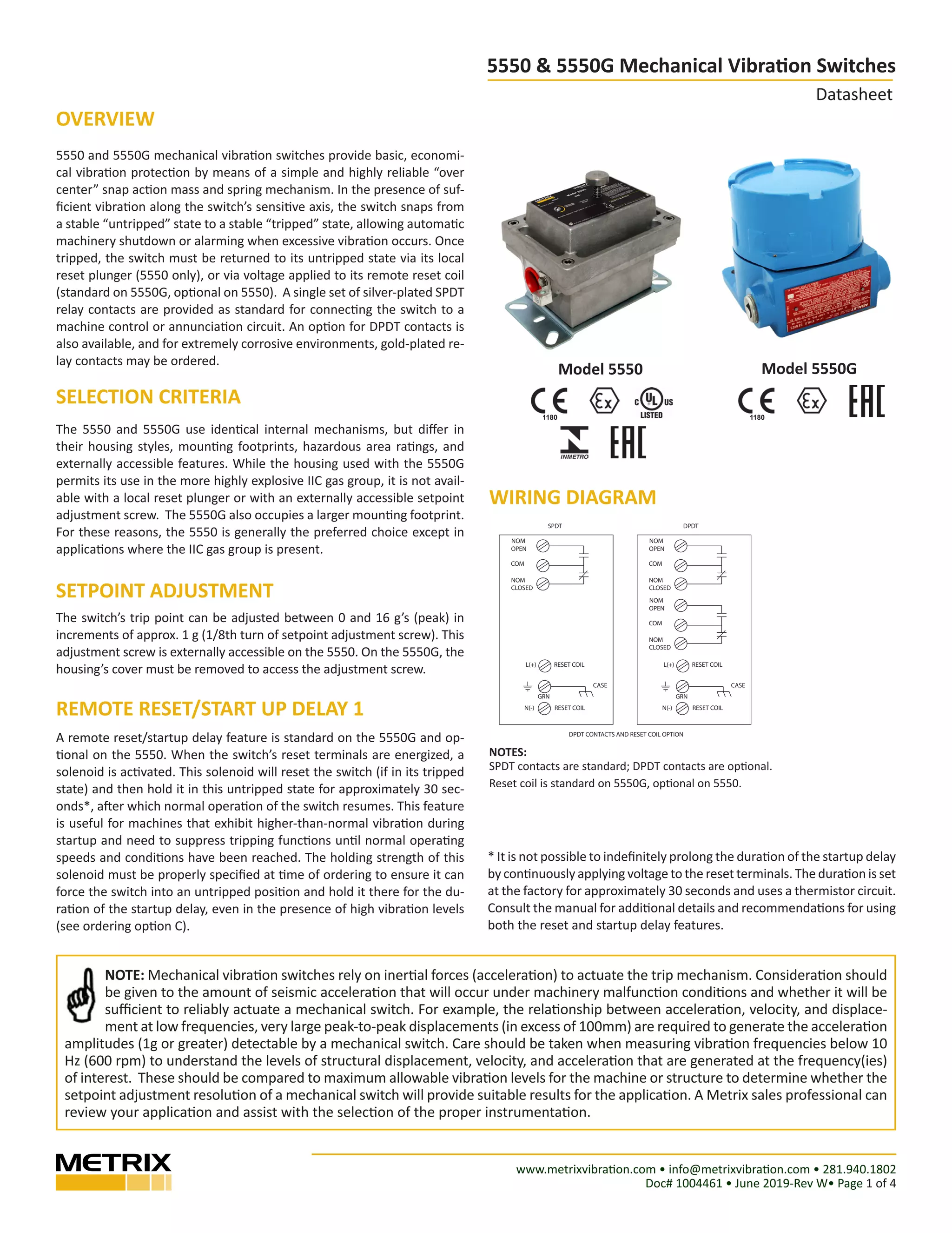
Model 5550 Model 5550G
5550 and 5550G mechanical vibration switches provide basic, economi-
cal vibration protection by means of a simple and highly reliable “over
center” snap action mass and spring mechanism. In the presence of suf-
ficient vibration along the switch’s sensitive axis, the switch snaps from
a stable “untripped” state to a stable “tripped” state, allowing automatic
machinery shutdown or alarming when excessive vibration occurs. Once
tripped, the switch must be returned to its untripped state via its local
reset plunger (5550 only), or via voltage applied to its remote reset coil
(standard on 5550G, optional on 5550). A single set of silver-plated SPDT
relay contacts are provided as standard for connecting the switch to a
machine control or annunciation circuit. An option for DPDT contacts is
also available, and for extremely corrosive environments, gold-plated re-
lay contacts may be ordered.
SELECTION CRITERIA
The 5550 and 5550G use identical internal mechanisms, but differ in
their housing styles, mounting footprints, hazardous area ratings, and
externally accessible features. While the housing used with the 5550G
permits its use in the more highly explosive IIC gas group, it is not avail-
able with a local reset plunger or with an externally accessible setpoint
adjustment screw. The 5550G also occupies a larger mounting footprint.
For these reasons, the 5550 is generally the preferred choice except in
applications where the IIC gas group is present.
SETPOINT ADJUSTMENT
The switch’s trip point can be adjusted between 0 and 16 g’s (peak) in
increments of approx. 1 g (1/8th turn of setpoint adjustment screw). This
adjustment screw is externally accessible on the 5550. On the 5550G, the
housing’s cover must be removed to access the adjustment screw.
A remote reset/startup delay feature is standard on the 5550G and op-
tional on the 5550. When the switch’s reset terminals are energized, a
solenoid is activated. This solenoid will reset the switch (if in its tripped
state) and then hold it in this untripped state for approximately 30 sec-
onds*, after which normal operation of the switch resumes. This feature
is useful for machines that exhibit higher-than-normal vibration during
startup and need to suppress tripping functions until normal operating
speeds and conditions have been reached. The holding strength of this
solenoid must be properly specified at time of ordering to ensure it can
force the switch into an untripped position and hold it there for the du-
ration of the startup delay, even in the presence of high vibration levels
(see ordering option C).
1180 1180
NOTES:
SPDT contacts are standard; DPDT contacts are optional.
Reset coil is standard on 5550G, optional on 5550.
NOTE: Mechanical vibration switches rely on inertial forces (acceleration) to actuate the trip mechanism. Consideration should
be given to the amount of seismic acceleration that will occur under machinery malfunction conditions and whether it will be
sufficient to reliably actuate a mechanical switch. For example, the relationship between acceleration, velocity, and displace-
ment at low frequencies, very large peak-to-peak displacements (in excess of 100mm) are required to generate the acceleration
amplitudes (1g or greater) detectable by a mechanical switch. Care should be taken when measuring vibration frequencies below 10
Hz (600 rpm) to understand the levels of structural displacement, velocity, and acceleration that are generated at the frequency(ies)
of interest. These should be compared to maximum allowable vibration levels for the machine or structure to determine whether the
setpoint adjustment resolution of a mechanical switch will provide suitable results for the application. A Metrix sales professional can
review your application and assist with the selection of the proper instrumentation.
* It is not possible to indefinitely prolong the duration of the startup delay
by continuously applying voltage to the reset terminals. The duration is set
at the factory for approximately 30 seconds and uses a thermistor circuit.
Consult the manual for additional details and recommendations for using
both the reset and startup delay features.
NOM
OPEN
COM
NOM
CLOSED
RESET COIL
CASE
RESET COIL
L(+)
N(-)
GRN
NOM
OPEN
COM
NOM
CLOSED
RESET COIL
CASE
RESET COIL
L(+)
N(-)
GRN
NOM
OPEN
COM
NOM
CLOSED
WIRING DIAGRAM
SPDT DPDT
DPDT CONTACTS AND RESET COIL OPTION
OVERVIEW
REMOTE RESET/START UP DELAY 1
WIRING DIAGRAM
www.metrixvibration.com • info@metrixvibration.com • 281.940.1802
Doc# 1004461 • June 2019-Rev W• Page 2 of 4
5550 & 5550G Mechanical Vibration Switches
Datasheet
All specifications are at +25°C (+77°F) unless otherwise noted.
5550 5550G
Amplitude Range 0 to 16 g pk
NOTE: Reset coil holding strength (option C) may limit the usable amplitude range of the switch when the startup delay
feature is required.
Frequency Range 0 – 60 Hz (0 – 3600 rpm)
Setpoint
Adjustment
Location: Externally Accessible Location: Internally Accessible (cover must be removed to ac-
cess)
Resolution: 1g (approximately 1/8th turn of adjustment screw where one full turn ≈ 8g)
Range: 0 – 100% of amplitude range
Wiring Entries One (3/4” NPT or M20 x 1.5 – see option E) Two (3/4” NPT only – see Figure 2)
Local Reset Manual plunger-style pushbutton on switch housing Not available (must use remote electrical reset)
Temperature Limit -40°C to +70°C (-40°F to +158°F)
-53°C to +70°C (-63°F to +158°F)* N/A
Mounting 4-hole rectangular in various dimensional options
(see Figure 1 and ordering option E)
2-hole rectangular (see Figure 2)
Remote Electrical Re-
set / Startup Delay
Optional (see ordering option D).
Applying a momentary voltage to the reset terminals will reset the switch to its untripped position.
Applying a persistent voltage to the reset terminals will suppress the trip mechanism from actuating for the duration of
voltage application or 30 seconds, whichever is less (a thermistor circuit limits the maximum delay time).
Reset Coil Holding
Strength
•	 2g, 5g, or 10g (see ordering option C). This option dictates the highest g-levels under which remote reset / startup
delay capabilities will still operate.
Enclosure
Material
•	 Copper-free cast aluminum (standard NEMA 4
version)
•	 Copper-free cast aluminum with clear epoxy
coating (optional NEMA 4X version)
Cast aluminum with blue epoxy coating
Environment Rating •	 NEMA 4 / IP66 (standard)
•	 NEMA 4X / IP66 (optional)
•	 NEMA 3 / IP64*
•	 NEMA 3X / IP64*
•	 NEMA 4 / IP66
Hazardous Area Rating Explosion Proof / Flameproof (IIB + H2
)
(see ordering option A)
Flameproof (IIC)
Agency
Certifications
ATEX / IECEx: Ex d IIB + H2 T6 Gb ATEX / IECEx: Ex d IIC T6 Gb
UL US/CA: Class I Div 1 Grps B,C,D
Class II Div 1 Grps E,F,G
INMETRO: Ex d IIB + H2 T6 Gb
EAC: 1Ex d IIB + H2 T6 Gb EAC: 1Ex d IIC T6 Gb
Weight 1.8 kg (4.0 lbs) 2.5 kg (5.5 lbs)
Contacts Type
SPDT (standard) DPDT (optional)
Plating Material
Silver (standard) Gold (optional)
Ratings
Silver-plated Gold-plated
15A @ 125-480 Vac 1A @ 125 Vac
1/4 hp @ 125 Vac
1/8 hp @ 250 Vac
0.5A @ 125 Vdc
0.25A @ 250 Vdc
SPECIFICATIONS
*For A = B or C and D = 0, F will = 3 or 4.
www.metrixvibration.com • info@metrixvibration.com • 281.940.1802
Doc# 1004461 • June 2019-Rev W• Page 3 of 4
5550 & 5550G Mechanical Vibration Switches
Datasheet
5550 Mechanical Vibration Switch
5550- A B C - D E F
A Hazardous Area Rating
0 None5
1 UL US/CA Explosion Proof2
Class I, Div 1, Groups C,D Class II, Div 1, Groups E,F,G
2 UL US/CA Explosion Proof2
Class I, Div 1, Groups B,C,D Class II, Div 1, Groups E,F,G
3 OBSOLETE, specify A=4 instead7
4 ATEX/IECEx Flameproof Ex d IIB+H2 T6 Gb
Ex tb IIIC T85°C Db Ta -40°C to +70°C IP66
5 OBSOLETE, same as A=0 but B=3 or 4 for gold contacts
6 OBSOLETE, same as A=1 but B=3 or 4 for gold contacts
7 OBSOLETE, same as A=2 but B=3 or 4 for gold contacts
8 OBSOLETE, specify A=9 instead7
9 OBSOLETE, same as A=4 but B=3 or 4 for gold contacts
10 OBSOLETE, specify A=11 instead7
11 INMETRO Flameproof, Ex d IIB + H2 T6 Gb1
Ex tb IIIC T85°C Db Ta -40°C to +70°C IP66
A EAC Flameproof, 1Ex d IIB + H2 T6 GbTa -40°C to +70°C
B ATEX/IECEx Flameproof Ex d IIB+H2 T6 Gb
Ex tb IIIC T85°C Db Ta -53°C to +70°C IP64 5
C EAC Flameproof, 1Ex d IIB + H2 T6 GbTa -53°C to +70°C 5
B Relay Contacts
1 SPDT, Silver, 15A1
2 DPDT, Silver, 15A1
3 SPDT, Gold, 1A
4 DPDT, Gold, 1A
C Reset / Startup Delay Coil Holding Strength6
1 5g
2 2g3
3 10g
D Reset / Startup Delay Coil Voltage
0 None5,6
1 115 Vac
2 230 Vac
3 24 Vdc3
4 115 Vdc
E Wiring Entry / Mounting Hole Pattern4
1 ¾” NPT / Metrix 5173 or 5175
2 ¾” NPT / Metrix 5097, VS-2 EX, or 366
3 ¾” NPT / Metrix 5078 or 365
4 M20 x 1.5 / Metrix 5097, VS-2 EX, or 3662
6 M20 x 1.5 / Metrix 5173 or 51752
7 ¾” NPT / Metrix or PMC-BETA 440
8 M20 x 1.5 / Metrix 5078 or 3652
5550G Mechanical Vibration Switch
5550- A B C - D E F
A Hazardous Area Rating
G ATEX / IECEx Flameproof
Ex d IIC T6 Gb (Ta -40°C to +70°C)
Ex tb IIIC T85°C Db Ta -40°C to +70°C IP66
EAC Flameproof
1Ex d IIC T6 Gb (Ta -40°C to +70°C)
B Relay Contacts
1 SPDT, Silver, 15A
2 DPDT, Silver, 15A
3 SPDT, Gold, 1A
4 DPDT, Gold, 1A
C Reset / Startup Delay Coil Holding Strength
1 5g
2 2g3
3 10g
D Reset / Startup Delay Coil Voltage
1 115 Vac
2 230 Vac
3 24 Vdc3
4 115 Vdc
E Wiring Entry / Mounting Hole Pattern8
9 ¾” NPT (2 places)
F Environmental Rating
2 IP66
NOTES:
1.	 INMETRO approvals (A=11) available with silver relay contacts only (B=1 or B=2)
2.	 UL US/CA approvals require tapered threads for conduit and are not compatible with
option E=4, E=6, or E=8.
3.	 When options C=2 and D=3 are simultaneously specified (2g, 24Vdc reset coil), the
switch sensitive axis (see Figure 1 for 5550 and Figure 2 for 5550G) MUST be oriented
vertically with the cover facing up. This coil lacks sufficient holding strength to support
the trip plate when the switch is mounted horizontally or upside down. The switch may
be mounted at any orientation for all other options.
4.	 Consult Figure 1 for mounting plate dimensions corresponding to E options.
5.	 For A = B or C and D = 0, F will = 3 or 4.
6.	 When D=0 (no reset /startup delay coil), the C option is ignored regardless of which
value is selected. All switches ship with a full-scale range of approximately 16gs.
7.	 Options A=3, A=8, and A=10 were all for Ex d IIB T6 Gb. These are now replaced by
the A=4, and A=11, respectively, which reflect the same approvals but with addition of
the H2 gas group.
8.	 Consult Figure 2 for mounting dimensions.
9 2
ORDERING INFORMATION
G
F Environmental Rating
0 NEMA 4 / IP66
1 NEMA 4X / IP66
3 NEMA 3 / IP645
4 NEMA 3X / IP645
www.metrixvibration.com • info@metrixvibration.com • 281.940.1802
Doc# 1004461 • June 2019-Rev W• Page 4 of 4
5550 & 5550G Mechanical Vibration Switches
Datasheet
Figure 1 – 5550 Mechanical Vibration Switch 
Figure 2 – 5550G Mechanical Vibration Switch
Units: mm [in]
Aprox. Weight: 1.8 kg (4 lbs)
Units: mm [in]
Aprox. Weight: 2.5 kg (5.5 lbs)
5550 OUTLINE & DIMENSIONS
5550G OUTLINE & DIMENSIONS

More Related Content

What's hot

Datablad opa627 operasjonsforsterer sven åge eriksen fagskolen telemark opamp...
Datablad opa627 operasjonsforsterer sven åge eriksen fagskolen telemark opamp...Datablad opa627 operasjonsforsterer sven åge eriksen fagskolen telemark opamp...
Datablad opa627 operasjonsforsterer sven åge eriksen fagskolen telemark opamp...Sven Åge Eriksen
 
Av02 3563 en-ds_acpl-c87x_04mar2013-2
Av02 3563 en-ds_acpl-c87x_04mar2013-2Av02 3563 en-ds_acpl-c87x_04mar2013-2
Av02 3563 en-ds_acpl-c87x_04mar2013-2srinivasponnaluri
 
Neutral grounding resistors ngr
Neutral grounding resistors  ngrNeutral grounding resistors  ngr
Neutral grounding resistors ngrJoeChueng
 
Kinetrol Universal Limit Switch
Kinetrol Universal Limit SwitchKinetrol Universal Limit Switch
Kinetrol Universal Limit SwitchKinetrol USA
 
Lv motor control_products_pricelist_w.e.f_1st_oct_2016
Lv motor control_products_pricelist_w.e.f_1st_oct_2016Lv motor control_products_pricelist_w.e.f_1st_oct_2016
Lv motor control_products_pricelist_w.e.f_1st_oct_2016Maxpromotion
 
Rotork YTC YT-2501 Smart Positioner Manual | YTC INDIA
Rotork YTC YT-2501 Smart Positioner Manual | YTC INDIARotork YTC YT-2501 Smart Positioner Manual | YTC INDIA
Rotork YTC YT-2501 Smart Positioner Manual | YTC INDIAYTC INDIA
 
Electronic Pressure Switch for Industrial Applications
Electronic Pressure Switch for Industrial ApplicationsElectronic Pressure Switch for Industrial Applications
Electronic Pressure Switch for Industrial ApplicationsM.S. Jacobs & Associates
 
Original IGBT GT40J323 40J323 TO-3P New TOSHIBA
Original IGBT GT40J323 40J323 TO-3P New TOSHIBAOriginal IGBT GT40J323 40J323 TO-3P New TOSHIBA
Original IGBT GT40J323 40J323 TO-3P New TOSHIBAauthelectroniccom
 

What's hot (20)

2 n6509g
2 n6509g2 n6509g
2 n6509g
 
Thông số kĩ thuật siemens monitoring devices
Thông số kĩ thuật siemens monitoring devicesThông số kĩ thuật siemens monitoring devices
Thông số kĩ thuật siemens monitoring devices
 
Datablad opa627 operasjonsforsterer sven åge eriksen fagskolen telemark opamp...
Datablad opa627 operasjonsforsterer sven åge eriksen fagskolen telemark opamp...Datablad opa627 operasjonsforsterer sven åge eriksen fagskolen telemark opamp...
Datablad opa627 operasjonsforsterer sven åge eriksen fagskolen telemark opamp...
 
Av02 3563 en-ds_acpl-c87x_04mar2013-2
Av02 3563 en-ds_acpl-c87x_04mar2013-2Av02 3563 en-ds_acpl-c87x_04mar2013-2
Av02 3563 en-ds_acpl-c87x_04mar2013-2
 
Thông số kĩ thuật siemens miniature circuit breakers
Thông số kĩ thuật siemens miniature circuit breakersThông số kĩ thuật siemens miniature circuit breakers
Thông số kĩ thuật siemens miniature circuit breakers
 
H355
H355H355
H355
 
Thông số kĩ thuật siemens rccb 5 sm
Thông số kĩ thuật siemens rccb 5 smThông số kĩ thuật siemens rccb 5 sm
Thông số kĩ thuật siemens rccb 5 sm
 
3000 001
3000 0013000 001
3000 001
 
Neutral grounding resistors ngr
Neutral grounding resistors  ngrNeutral grounding resistors  ngr
Neutral grounding resistors ngr
 
Hci5 d
Hci5 dHci5 d
Hci5 d
 
Kinetrol Universal Limit Switch
Kinetrol Universal Limit SwitchKinetrol Universal Limit Switch
Kinetrol Universal Limit Switch
 
Lv motor control_products_pricelist_w.e.f_1st_oct_2016
Lv motor control_products_pricelist_w.e.f_1st_oct_2016Lv motor control_products_pricelist_w.e.f_1st_oct_2016
Lv motor control_products_pricelist_w.e.f_1st_oct_2016
 
Catalog terminal Idec
Catalog terminal IdecCatalog terminal Idec
Catalog terminal Idec
 
4000 001
4000 0014000 001
4000 001
 
Thông số bộ đổi nguồn Mean Well, Catalogue Bộ đổi nguồn Mean Well, Meanwell
Thông số bộ đổi nguồn Mean Well, Catalogue Bộ đổi nguồn Mean Well, MeanwellThông số bộ đổi nguồn Mean Well, Catalogue Bộ đổi nguồn Mean Well, Meanwell
Thông số bộ đổi nguồn Mean Well, Catalogue Bộ đổi nguồn Mean Well, Meanwell
 
Sunan
SunanSunan
Sunan
 
Rotork YTC YT-2501 Smart Positioner Manual | YTC INDIA
Rotork YTC YT-2501 Smart Positioner Manual | YTC INDIARotork YTC YT-2501 Smart Positioner Manual | YTC INDIA
Rotork YTC YT-2501 Smart Positioner Manual | YTC INDIA
 
Sicop datasheet
Sicop datasheetSicop datasheet
Sicop datasheet
 
Electronic Pressure Switch for Industrial Applications
Electronic Pressure Switch for Industrial ApplicationsElectronic Pressure Switch for Industrial Applications
Electronic Pressure Switch for Industrial Applications
 
Original IGBT GT40J323 40J323 TO-3P New TOSHIBA
Original IGBT GT40J323 40J323 TO-3P New TOSHIBAOriginal IGBT GT40J323 40J323 TO-3P New TOSHIBA
Original IGBT GT40J323 40J323 TO-3P New TOSHIBA
 

Similar to Matrix

Advanced motion controls s30a40
Advanced motion controls s30a40Advanced motion controls s30a40
Advanced motion controls s30a40Electromate
 
Advanced motion controls s60a40
Advanced motion controls s60a40Advanced motion controls s60a40
Advanced motion controls s60a40Electromate
 
Advanced motion controls s60a8
Advanced motion controls s60a8Advanced motion controls s60a8
Advanced motion controls s60a8Electromate
 
Advanced motion controls sx30a8
Advanced motion controls sx30a8Advanced motion controls sx30a8
Advanced motion controls sx30a8Electromate
 
Advanced motion controls s100a8
Advanced motion controls s100a8Advanced motion controls s100a8
Advanced motion controls s100a8Electromate
 
ARTECHE_CT_LATCHING-RELAYS_EN
ARTECHE_CT_LATCHING-RELAYS_ENARTECHE_CT_LATCHING-RELAYS_EN
ARTECHE_CT_LATCHING-RELAYS_ENMarius Spamers
 
Bta08 600 bw3-d tiristor bidireccional
Bta08 600 bw3-d  tiristor bidireccionalBta08 600 bw3-d  tiristor bidireccional
Bta08 600 bw3-d tiristor bidireccional8525
 
Advanced motion controls s100a20
Advanced motion controls s100a20Advanced motion controls s100a20
Advanced motion controls s100a20Electromate
 
Vibrating Tuning Fork Level Switch
Vibrating Tuning Fork Level SwitchVibrating Tuning Fork Level Switch
Vibrating Tuning Fork Level SwitchCTi Controltech
 
Advanced motion controls s16a8
Advanced motion controls s16a8Advanced motion controls s16a8
Advanced motion controls s16a8Electromate
 
Advanced motion controls s30a40ac
Advanced motion controls s30a40acAdvanced motion controls s30a40ac
Advanced motion controls s30a40acElectromate
 
Advanced motion controls s60a40ac
Advanced motion controls s60a40acAdvanced motion controls s60a40ac
Advanced motion controls s60a40acElectromate
 
Dienhathe.com semiconductor fuses
Dienhathe.com semiconductor fusesDienhathe.com semiconductor fuses
Dienhathe.com semiconductor fusesDien Ha The
 
Advanced motion controls s100a40ac
Advanced motion controls s100a40acAdvanced motion controls s100a40ac
Advanced motion controls s100a40acElectromate
 
Jvc mx g75v-g78v_gt85v_gt88v_gt95v_gt98v
Jvc mx g75v-g78v_gt85v_gt88v_gt95v_gt98vJvc mx g75v-g78v_gt85v_gt88v_gt95v_gt98v
Jvc mx g75v-g78v_gt85v_gt88v_gt95v_gt98vsophon505
 
Cdvr service manual renr7941-00 _ sis - caterpillar
Cdvr   service manual   renr7941-00 _ sis - caterpillarCdvr   service manual   renr7941-00 _ sis - caterpillar
Cdvr service manual renr7941-00 _ sis - caterpillarOtorongosabroso
 

Similar to Matrix (20)

Advanced motion controls s30a40
Advanced motion controls s30a40Advanced motion controls s30a40
Advanced motion controls s30a40
 
Advanced motion controls s60a40
Advanced motion controls s60a40Advanced motion controls s60a40
Advanced motion controls s60a40
 
Advanced motion controls s60a8
Advanced motion controls s60a8Advanced motion controls s60a8
Advanced motion controls s60a8
 
Advanced motion controls sx30a8
Advanced motion controls sx30a8Advanced motion controls sx30a8
Advanced motion controls sx30a8
 
Advanced motion controls s100a8
Advanced motion controls s100a8Advanced motion controls s100a8
Advanced motion controls s100a8
 
EAPL TIMER & CONTROLLER PRICE LIST wef 01-08-2022.pdf
EAPL TIMER & CONTROLLER PRICE LIST wef 01-08-2022.pdfEAPL TIMER & CONTROLLER PRICE LIST wef 01-08-2022.pdf
EAPL TIMER & CONTROLLER PRICE LIST wef 01-08-2022.pdf
 
ARTECHE_CT_LATCHING-RELAYS_EN
ARTECHE_CT_LATCHING-RELAYS_ENARTECHE_CT_LATCHING-RELAYS_EN
ARTECHE_CT_LATCHING-RELAYS_EN
 
Bta08 600 bw3-d tiristor bidireccional
Bta08 600 bw3-d  tiristor bidireccionalBta08 600 bw3-d  tiristor bidireccional
Bta08 600 bw3-d tiristor bidireccional
 
Advanced motion controls s100a20
Advanced motion controls s100a20Advanced motion controls s100a20
Advanced motion controls s100a20
 
Vibrating Tuning Fork Level Switch
Vibrating Tuning Fork Level SwitchVibrating Tuning Fork Level Switch
Vibrating Tuning Fork Level Switch
 
Advanced motion controls s16a8
Advanced motion controls s16a8Advanced motion controls s16a8
Advanced motion controls s16a8
 
Advanced motion controls s30a40ac
Advanced motion controls s30a40acAdvanced motion controls s30a40ac
Advanced motion controls s30a40ac
 
Advanced motion controls s60a40ac
Advanced motion controls s60a40acAdvanced motion controls s60a40ac
Advanced motion controls s60a40ac
 
Catalogue siemens MCB6 SX
Catalogue siemens MCB6 SXCatalogue siemens MCB6 SX
Catalogue siemens MCB6 SX
 
HIA.PDF
HIA.PDFHIA.PDF
HIA.PDF
 
Dienhathe.com semiconductor fuses
Dienhathe.com semiconductor fusesDienhathe.com semiconductor fuses
Dienhathe.com semiconductor fuses
 
Advanced motion controls s100a40ac
Advanced motion controls s100a40acAdvanced motion controls s100a40ac
Advanced motion controls s100a40ac
 
Triac 2 n6073a
Triac 2 n6073aTriac 2 n6073a
Triac 2 n6073a
 
Jvc mx g75v-g78v_gt85v_gt88v_gt95v_gt98v
Jvc mx g75v-g78v_gt85v_gt88v_gt95v_gt98vJvc mx g75v-g78v_gt85v_gt88v_gt95v_gt98v
Jvc mx g75v-g78v_gt85v_gt88v_gt95v_gt98v
 
Cdvr service manual renr7941-00 _ sis - caterpillar
Cdvr   service manual   renr7941-00 _ sis - caterpillarCdvr   service manual   renr7941-00 _ sis - caterpillar
Cdvr service manual renr7941-00 _ sis - caterpillar
 

Recently uploaded

KubeKraft presentation @CloudNativeHooghly
KubeKraft presentation @CloudNativeHooghlyKubeKraft presentation @CloudNativeHooghly
KubeKraft presentation @CloudNativeHooghlysanyuktamishra911
 
MANUFACTURING PROCESS-II UNIT-2 LATHE MACHINE
MANUFACTURING PROCESS-II UNIT-2 LATHE MACHINEMANUFACTURING PROCESS-II UNIT-2 LATHE MACHINE
MANUFACTURING PROCESS-II UNIT-2 LATHE MACHINESIVASHANKAR N
 
IMPLICATIONS OF THE ABOVE HOLISTIC UNDERSTANDING OF HARMONY ON PROFESSIONAL E...
IMPLICATIONS OF THE ABOVE HOLISTIC UNDERSTANDING OF HARMONY ON PROFESSIONAL E...IMPLICATIONS OF THE ABOVE HOLISTIC UNDERSTANDING OF HARMONY ON PROFESSIONAL E...
IMPLICATIONS OF THE ABOVE HOLISTIC UNDERSTANDING OF HARMONY ON PROFESSIONAL E...RajaP95
 
Porous Ceramics seminar and technical writing
Porous Ceramics seminar and technical writingPorous Ceramics seminar and technical writing
Porous Ceramics seminar and technical writingrakeshbaidya232001
 
HARMONY IN THE NATURE AND EXISTENCE - Unit-IV
HARMONY IN THE NATURE AND EXISTENCE - Unit-IVHARMONY IN THE NATURE AND EXISTENCE - Unit-IV
HARMONY IN THE NATURE AND EXISTENCE - Unit-IVRajaP95
 
APPLICATIONS-AC/DC DRIVES-OPERATING CHARACTERISTICS
APPLICATIONS-AC/DC DRIVES-OPERATING CHARACTERISTICSAPPLICATIONS-AC/DC DRIVES-OPERATING CHARACTERISTICS
APPLICATIONS-AC/DC DRIVES-OPERATING CHARACTERISTICSKurinjimalarL3
 
UNIT - IV - Air Compressors and its Performance
UNIT - IV - Air Compressors and its PerformanceUNIT - IV - Air Compressors and its Performance
UNIT - IV - Air Compressors and its Performancesivaprakash250
 
Introduction and different types of Ethernet.pptx
Introduction and different types of Ethernet.pptxIntroduction and different types of Ethernet.pptx
Introduction and different types of Ethernet.pptxupamatechverse
 
Microscopic Analysis of Ceramic Materials.pptx
Microscopic Analysis of Ceramic Materials.pptxMicroscopic Analysis of Ceramic Materials.pptx
Microscopic Analysis of Ceramic Materials.pptxpurnimasatapathy1234
 
College Call Girls Nashik Nehal 7001305949 Independent Escort Service Nashik
College Call Girls Nashik Nehal 7001305949 Independent Escort Service NashikCollege Call Girls Nashik Nehal 7001305949 Independent Escort Service Nashik
College Call Girls Nashik Nehal 7001305949 Independent Escort Service NashikCall Girls in Nagpur High Profile
 
HARDNESS, FRACTURE TOUGHNESS AND STRENGTH OF CERAMICS
HARDNESS, FRACTURE TOUGHNESS AND STRENGTH OF CERAMICSHARDNESS, FRACTURE TOUGHNESS AND STRENGTH OF CERAMICS
HARDNESS, FRACTURE TOUGHNESS AND STRENGTH OF CERAMICSRajkumarAkumalla
 
Introduction to IEEE STANDARDS and its different types.pptx
Introduction to IEEE STANDARDS and its different types.pptxIntroduction to IEEE STANDARDS and its different types.pptx
Introduction to IEEE STANDARDS and its different types.pptxupamatechverse
 
Call Girls Service Nagpur Tanvi Call 7001035870 Meet With Nagpur Escorts
Call Girls Service Nagpur Tanvi Call 7001035870 Meet With Nagpur EscortsCall Girls Service Nagpur Tanvi Call 7001035870 Meet With Nagpur Escorts
Call Girls Service Nagpur Tanvi Call 7001035870 Meet With Nagpur EscortsCall Girls in Nagpur High Profile
 
CCS335 _ Neural Networks and Deep Learning Laboratory_Lab Complete Record
CCS335 _ Neural Networks and Deep Learning Laboratory_Lab Complete RecordCCS335 _ Neural Networks and Deep Learning Laboratory_Lab Complete Record
CCS335 _ Neural Networks and Deep Learning Laboratory_Lab Complete RecordAsst.prof M.Gokilavani
 
UNIT-V FMM.HYDRAULIC TURBINE - Construction and working
UNIT-V FMM.HYDRAULIC TURBINE - Construction and workingUNIT-V FMM.HYDRAULIC TURBINE - Construction and working
UNIT-V FMM.HYDRAULIC TURBINE - Construction and workingrknatarajan
 
UNIT-III FMM. DIMENSIONAL ANALYSIS
UNIT-III FMM.        DIMENSIONAL ANALYSISUNIT-III FMM.        DIMENSIONAL ANALYSIS
UNIT-III FMM. DIMENSIONAL ANALYSISrknatarajan
 
(SHREYA) Chakan Call Girls Just Call 7001035870 [ Cash on Delivery ] Pune Esc...
(SHREYA) Chakan Call Girls Just Call 7001035870 [ Cash on Delivery ] Pune Esc...(SHREYA) Chakan Call Girls Just Call 7001035870 [ Cash on Delivery ] Pune Esc...
(SHREYA) Chakan Call Girls Just Call 7001035870 [ Cash on Delivery ] Pune Esc...ranjana rawat
 
(ANJALI) Dange Chowk Call Girls Just Call 7001035870 [ Cash on Delivery ] Pun...
(ANJALI) Dange Chowk Call Girls Just Call 7001035870 [ Cash on Delivery ] Pun...(ANJALI) Dange Chowk Call Girls Just Call 7001035870 [ Cash on Delivery ] Pun...
(ANJALI) Dange Chowk Call Girls Just Call 7001035870 [ Cash on Delivery ] Pun...ranjana rawat
 
Top Rated Pune Call Girls Budhwar Peth ⟟ 6297143586 ⟟ Call Me For Genuine Se...
Top Rated  Pune Call Girls Budhwar Peth ⟟ 6297143586 ⟟ Call Me For Genuine Se...Top Rated  Pune Call Girls Budhwar Peth ⟟ 6297143586 ⟟ Call Me For Genuine Se...
Top Rated Pune Call Girls Budhwar Peth ⟟ 6297143586 ⟟ Call Me For Genuine Se...Call Girls in Nagpur High Profile
 

Recently uploaded (20)

KubeKraft presentation @CloudNativeHooghly
KubeKraft presentation @CloudNativeHooghlyKubeKraft presentation @CloudNativeHooghly
KubeKraft presentation @CloudNativeHooghly
 
MANUFACTURING PROCESS-II UNIT-2 LATHE MACHINE
MANUFACTURING PROCESS-II UNIT-2 LATHE MACHINEMANUFACTURING PROCESS-II UNIT-2 LATHE MACHINE
MANUFACTURING PROCESS-II UNIT-2 LATHE MACHINE
 
IMPLICATIONS OF THE ABOVE HOLISTIC UNDERSTANDING OF HARMONY ON PROFESSIONAL E...
IMPLICATIONS OF THE ABOVE HOLISTIC UNDERSTANDING OF HARMONY ON PROFESSIONAL E...IMPLICATIONS OF THE ABOVE HOLISTIC UNDERSTANDING OF HARMONY ON PROFESSIONAL E...
IMPLICATIONS OF THE ABOVE HOLISTIC UNDERSTANDING OF HARMONY ON PROFESSIONAL E...
 
Porous Ceramics seminar and technical writing
Porous Ceramics seminar and technical writingPorous Ceramics seminar and technical writing
Porous Ceramics seminar and technical writing
 
HARMONY IN THE NATURE AND EXISTENCE - Unit-IV
HARMONY IN THE NATURE AND EXISTENCE - Unit-IVHARMONY IN THE NATURE AND EXISTENCE - Unit-IV
HARMONY IN THE NATURE AND EXISTENCE - Unit-IV
 
APPLICATIONS-AC/DC DRIVES-OPERATING CHARACTERISTICS
APPLICATIONS-AC/DC DRIVES-OPERATING CHARACTERISTICSAPPLICATIONS-AC/DC DRIVES-OPERATING CHARACTERISTICS
APPLICATIONS-AC/DC DRIVES-OPERATING CHARACTERISTICS
 
UNIT - IV - Air Compressors and its Performance
UNIT - IV - Air Compressors and its PerformanceUNIT - IV - Air Compressors and its Performance
UNIT - IV - Air Compressors and its Performance
 
Introduction and different types of Ethernet.pptx
Introduction and different types of Ethernet.pptxIntroduction and different types of Ethernet.pptx
Introduction and different types of Ethernet.pptx
 
Microscopic Analysis of Ceramic Materials.pptx
Microscopic Analysis of Ceramic Materials.pptxMicroscopic Analysis of Ceramic Materials.pptx
Microscopic Analysis of Ceramic Materials.pptx
 
College Call Girls Nashik Nehal 7001305949 Independent Escort Service Nashik
College Call Girls Nashik Nehal 7001305949 Independent Escort Service NashikCollege Call Girls Nashik Nehal 7001305949 Independent Escort Service Nashik
College Call Girls Nashik Nehal 7001305949 Independent Escort Service Nashik
 
HARDNESS, FRACTURE TOUGHNESS AND STRENGTH OF CERAMICS
HARDNESS, FRACTURE TOUGHNESS AND STRENGTH OF CERAMICSHARDNESS, FRACTURE TOUGHNESS AND STRENGTH OF CERAMICS
HARDNESS, FRACTURE TOUGHNESS AND STRENGTH OF CERAMICS
 
Introduction to IEEE STANDARDS and its different types.pptx
Introduction to IEEE STANDARDS and its different types.pptxIntroduction to IEEE STANDARDS and its different types.pptx
Introduction to IEEE STANDARDS and its different types.pptx
 
Call Girls Service Nagpur Tanvi Call 7001035870 Meet With Nagpur Escorts
Call Girls Service Nagpur Tanvi Call 7001035870 Meet With Nagpur EscortsCall Girls Service Nagpur Tanvi Call 7001035870 Meet With Nagpur Escorts
Call Girls Service Nagpur Tanvi Call 7001035870 Meet With Nagpur Escorts
 
CCS335 _ Neural Networks and Deep Learning Laboratory_Lab Complete Record
CCS335 _ Neural Networks and Deep Learning Laboratory_Lab Complete RecordCCS335 _ Neural Networks and Deep Learning Laboratory_Lab Complete Record
CCS335 _ Neural Networks and Deep Learning Laboratory_Lab Complete Record
 
UNIT-V FMM.HYDRAULIC TURBINE - Construction and working
UNIT-V FMM.HYDRAULIC TURBINE - Construction and workingUNIT-V FMM.HYDRAULIC TURBINE - Construction and working
UNIT-V FMM.HYDRAULIC TURBINE - Construction and working
 
UNIT-III FMM. DIMENSIONAL ANALYSIS
UNIT-III FMM.        DIMENSIONAL ANALYSISUNIT-III FMM.        DIMENSIONAL ANALYSIS
UNIT-III FMM. DIMENSIONAL ANALYSIS
 
Roadmap to Membership of RICS - Pathways and Routes
Roadmap to Membership of RICS - Pathways and RoutesRoadmap to Membership of RICS - Pathways and Routes
Roadmap to Membership of RICS - Pathways and Routes
 
(SHREYA) Chakan Call Girls Just Call 7001035870 [ Cash on Delivery ] Pune Esc...
(SHREYA) Chakan Call Girls Just Call 7001035870 [ Cash on Delivery ] Pune Esc...(SHREYA) Chakan Call Girls Just Call 7001035870 [ Cash on Delivery ] Pune Esc...
(SHREYA) Chakan Call Girls Just Call 7001035870 [ Cash on Delivery ] Pune Esc...
 
(ANJALI) Dange Chowk Call Girls Just Call 7001035870 [ Cash on Delivery ] Pun...
(ANJALI) Dange Chowk Call Girls Just Call 7001035870 [ Cash on Delivery ] Pun...(ANJALI) Dange Chowk Call Girls Just Call 7001035870 [ Cash on Delivery ] Pun...
(ANJALI) Dange Chowk Call Girls Just Call 7001035870 [ Cash on Delivery ] Pun...
 
Top Rated Pune Call Girls Budhwar Peth ⟟ 6297143586 ⟟ Call Me For Genuine Se...
Top Rated  Pune Call Girls Budhwar Peth ⟟ 6297143586 ⟟ Call Me For Genuine Se...Top Rated  Pune Call Girls Budhwar Peth ⟟ 6297143586 ⟟ Call Me For Genuine Se...
Top Rated Pune Call Girls Budhwar Peth ⟟ 6297143586 ⟟ Call Me For Genuine Se...
 

Matrix

  • 1. www.metrixvibration.com • info@metrixvibration.com • 281.940.1802 Doc# 1004461 • June 2019-Rev W• Page 1 of 4 5550 & 5550G Mechanical Vibration Switches Datasheet Model 5550 Model 5550G 5550 and 5550G mechanical vibration switches provide basic, economi- cal vibration protection by means of a simple and highly reliable “over center” snap action mass and spring mechanism. In the presence of suf- ficient vibration along the switch’s sensitive axis, the switch snaps from a stable “untripped” state to a stable “tripped” state, allowing automatic machinery shutdown or alarming when excessive vibration occurs. Once tripped, the switch must be returned to its untripped state via its local reset plunger (5550 only), or via voltage applied to its remote reset coil (standard on 5550G, optional on 5550). A single set of silver-plated SPDT relay contacts are provided as standard for connecting the switch to a machine control or annunciation circuit. An option for DPDT contacts is also available, and for extremely corrosive environments, gold-plated re- lay contacts may be ordered. SELECTION CRITERIA The 5550 and 5550G use identical internal mechanisms, but differ in their housing styles, mounting footprints, hazardous area ratings, and externally accessible features. While the housing used with the 5550G permits its use in the more highly explosive IIC gas group, it is not avail- able with a local reset plunger or with an externally accessible setpoint adjustment screw. The 5550G also occupies a larger mounting footprint. For these reasons, the 5550 is generally the preferred choice except in applications where the IIC gas group is present. SETPOINT ADJUSTMENT The switch’s trip point can be adjusted between 0 and 16 g’s (peak) in increments of approx. 1 g (1/8th turn of setpoint adjustment screw). This adjustment screw is externally accessible on the 5550. On the 5550G, the housing’s cover must be removed to access the adjustment screw. A remote reset/startup delay feature is standard on the 5550G and op- tional on the 5550. When the switch’s reset terminals are energized, a solenoid is activated. This solenoid will reset the switch (if in its tripped state) and then hold it in this untripped state for approximately 30 sec- onds*, after which normal operation of the switch resumes. This feature is useful for machines that exhibit higher-than-normal vibration during startup and need to suppress tripping functions until normal operating speeds and conditions have been reached. The holding strength of this solenoid must be properly specified at time of ordering to ensure it can force the switch into an untripped position and hold it there for the du- ration of the startup delay, even in the presence of high vibration levels (see ordering option C). 1180 1180 NOTES: SPDT contacts are standard; DPDT contacts are optional. Reset coil is standard on 5550G, optional on 5550. NOTE: Mechanical vibration switches rely on inertial forces (acceleration) to actuate the trip mechanism. Consideration should be given to the amount of seismic acceleration that will occur under machinery malfunction conditions and whether it will be sufficient to reliably actuate a mechanical switch. For example, the relationship between acceleration, velocity, and displace- ment at low frequencies, very large peak-to-peak displacements (in excess of 100mm) are required to generate the acceleration amplitudes (1g or greater) detectable by a mechanical switch. Care should be taken when measuring vibration frequencies below 10 Hz (600 rpm) to understand the levels of structural displacement, velocity, and acceleration that are generated at the frequency(ies) of interest. These should be compared to maximum allowable vibration levels for the machine or structure to determine whether the setpoint adjustment resolution of a mechanical switch will provide suitable results for the application. A Metrix sales professional can review your application and assist with the selection of the proper instrumentation. * It is not possible to indefinitely prolong the duration of the startup delay by continuously applying voltage to the reset terminals. The duration is set at the factory for approximately 30 seconds and uses a thermistor circuit. Consult the manual for additional details and recommendations for using both the reset and startup delay features. NOM OPEN COM NOM CLOSED RESET COIL CASE RESET COIL L(+) N(-) GRN NOM OPEN COM NOM CLOSED RESET COIL CASE RESET COIL L(+) N(-) GRN NOM OPEN COM NOM CLOSED WIRING DIAGRAM SPDT DPDT DPDT CONTACTS AND RESET COIL OPTION OVERVIEW REMOTE RESET/START UP DELAY 1 WIRING DIAGRAM
  • 2. www.metrixvibration.com • info@metrixvibration.com • 281.940.1802 Doc# 1004461 • June 2019-Rev W• Page 2 of 4 5550 & 5550G Mechanical Vibration Switches Datasheet All specifications are at +25°C (+77°F) unless otherwise noted. 5550 5550G Amplitude Range 0 to 16 g pk NOTE: Reset coil holding strength (option C) may limit the usable amplitude range of the switch when the startup delay feature is required. Frequency Range 0 – 60 Hz (0 – 3600 rpm) Setpoint Adjustment Location: Externally Accessible Location: Internally Accessible (cover must be removed to ac- cess) Resolution: 1g (approximately 1/8th turn of adjustment screw where one full turn ≈ 8g) Range: 0 – 100% of amplitude range Wiring Entries One (3/4” NPT or M20 x 1.5 – see option E) Two (3/4” NPT only – see Figure 2) Local Reset Manual plunger-style pushbutton on switch housing Not available (must use remote electrical reset) Temperature Limit -40°C to +70°C (-40°F to +158°F) -53°C to +70°C (-63°F to +158°F)* N/A Mounting 4-hole rectangular in various dimensional options (see Figure 1 and ordering option E) 2-hole rectangular (see Figure 2) Remote Electrical Re- set / Startup Delay Optional (see ordering option D). Applying a momentary voltage to the reset terminals will reset the switch to its untripped position. Applying a persistent voltage to the reset terminals will suppress the trip mechanism from actuating for the duration of voltage application or 30 seconds, whichever is less (a thermistor circuit limits the maximum delay time). Reset Coil Holding Strength • 2g, 5g, or 10g (see ordering option C). This option dictates the highest g-levels under which remote reset / startup delay capabilities will still operate. Enclosure Material • Copper-free cast aluminum (standard NEMA 4 version) • Copper-free cast aluminum with clear epoxy coating (optional NEMA 4X version) Cast aluminum with blue epoxy coating Environment Rating • NEMA 4 / IP66 (standard) • NEMA 4X / IP66 (optional) • NEMA 3 / IP64* • NEMA 3X / IP64* • NEMA 4 / IP66 Hazardous Area Rating Explosion Proof / Flameproof (IIB + H2 ) (see ordering option A) Flameproof (IIC) Agency Certifications ATEX / IECEx: Ex d IIB + H2 T6 Gb ATEX / IECEx: Ex d IIC T6 Gb UL US/CA: Class I Div 1 Grps B,C,D Class II Div 1 Grps E,F,G INMETRO: Ex d IIB + H2 T6 Gb EAC: 1Ex d IIB + H2 T6 Gb EAC: 1Ex d IIC T6 Gb Weight 1.8 kg (4.0 lbs) 2.5 kg (5.5 lbs) Contacts Type SPDT (standard) DPDT (optional) Plating Material Silver (standard) Gold (optional) Ratings Silver-plated Gold-plated 15A @ 125-480 Vac 1A @ 125 Vac 1/4 hp @ 125 Vac 1/8 hp @ 250 Vac 0.5A @ 125 Vdc 0.25A @ 250 Vdc SPECIFICATIONS *For A = B or C and D = 0, F will = 3 or 4.
  • 3. www.metrixvibration.com • info@metrixvibration.com • 281.940.1802 Doc# 1004461 • June 2019-Rev W• Page 3 of 4 5550 & 5550G Mechanical Vibration Switches Datasheet 5550 Mechanical Vibration Switch 5550- A B C - D E F A Hazardous Area Rating 0 None5 1 UL US/CA Explosion Proof2 Class I, Div 1, Groups C,D Class II, Div 1, Groups E,F,G 2 UL US/CA Explosion Proof2 Class I, Div 1, Groups B,C,D Class II, Div 1, Groups E,F,G 3 OBSOLETE, specify A=4 instead7 4 ATEX/IECEx Flameproof Ex d IIB+H2 T6 Gb Ex tb IIIC T85°C Db Ta -40°C to +70°C IP66 5 OBSOLETE, same as A=0 but B=3 or 4 for gold contacts 6 OBSOLETE, same as A=1 but B=3 or 4 for gold contacts 7 OBSOLETE, same as A=2 but B=3 or 4 for gold contacts 8 OBSOLETE, specify A=9 instead7 9 OBSOLETE, same as A=4 but B=3 or 4 for gold contacts 10 OBSOLETE, specify A=11 instead7 11 INMETRO Flameproof, Ex d IIB + H2 T6 Gb1 Ex tb IIIC T85°C Db Ta -40°C to +70°C IP66 A EAC Flameproof, 1Ex d IIB + H2 T6 GbTa -40°C to +70°C B ATEX/IECEx Flameproof Ex d IIB+H2 T6 Gb Ex tb IIIC T85°C Db Ta -53°C to +70°C IP64 5 C EAC Flameproof, 1Ex d IIB + H2 T6 GbTa -53°C to +70°C 5 B Relay Contacts 1 SPDT, Silver, 15A1 2 DPDT, Silver, 15A1 3 SPDT, Gold, 1A 4 DPDT, Gold, 1A C Reset / Startup Delay Coil Holding Strength6 1 5g 2 2g3 3 10g D Reset / Startup Delay Coil Voltage 0 None5,6 1 115 Vac 2 230 Vac 3 24 Vdc3 4 115 Vdc E Wiring Entry / Mounting Hole Pattern4 1 ¾” NPT / Metrix 5173 or 5175 2 ¾” NPT / Metrix 5097, VS-2 EX, or 366 3 ¾” NPT / Metrix 5078 or 365 4 M20 x 1.5 / Metrix 5097, VS-2 EX, or 3662 6 M20 x 1.5 / Metrix 5173 or 51752 7 ¾” NPT / Metrix or PMC-BETA 440 8 M20 x 1.5 / Metrix 5078 or 3652 5550G Mechanical Vibration Switch 5550- A B C - D E F A Hazardous Area Rating G ATEX / IECEx Flameproof Ex d IIC T6 Gb (Ta -40°C to +70°C) Ex tb IIIC T85°C Db Ta -40°C to +70°C IP66 EAC Flameproof 1Ex d IIC T6 Gb (Ta -40°C to +70°C) B Relay Contacts 1 SPDT, Silver, 15A 2 DPDT, Silver, 15A 3 SPDT, Gold, 1A 4 DPDT, Gold, 1A C Reset / Startup Delay Coil Holding Strength 1 5g 2 2g3 3 10g D Reset / Startup Delay Coil Voltage 1 115 Vac 2 230 Vac 3 24 Vdc3 4 115 Vdc E Wiring Entry / Mounting Hole Pattern8 9 ¾” NPT (2 places) F Environmental Rating 2 IP66 NOTES: 1. INMETRO approvals (A=11) available with silver relay contacts only (B=1 or B=2) 2. UL US/CA approvals require tapered threads for conduit and are not compatible with option E=4, E=6, or E=8. 3. When options C=2 and D=3 are simultaneously specified (2g, 24Vdc reset coil), the switch sensitive axis (see Figure 1 for 5550 and Figure 2 for 5550G) MUST be oriented vertically with the cover facing up. This coil lacks sufficient holding strength to support the trip plate when the switch is mounted horizontally or upside down. The switch may be mounted at any orientation for all other options. 4. Consult Figure 1 for mounting plate dimensions corresponding to E options. 5. For A = B or C and D = 0, F will = 3 or 4. 6. When D=0 (no reset /startup delay coil), the C option is ignored regardless of which value is selected. All switches ship with a full-scale range of approximately 16gs. 7. Options A=3, A=8, and A=10 were all for Ex d IIB T6 Gb. These are now replaced by the A=4, and A=11, respectively, which reflect the same approvals but with addition of the H2 gas group. 8. Consult Figure 2 for mounting dimensions. 9 2 ORDERING INFORMATION G F Environmental Rating 0 NEMA 4 / IP66 1 NEMA 4X / IP66 3 NEMA 3 / IP645 4 NEMA 3X / IP645
  • 4. www.metrixvibration.com • info@metrixvibration.com • 281.940.1802 Doc# 1004461 • June 2019-Rev W• Page 4 of 4 5550 & 5550G Mechanical Vibration Switches Datasheet Figure 1 – 5550 Mechanical Vibration Switch  Figure 2 – 5550G Mechanical Vibration Switch Units: mm [in] Aprox. Weight: 1.8 kg (4 lbs) Units: mm [in] Aprox. Weight: 2.5 kg (5.5 lbs) 5550 OUTLINE & DIMENSIONS 5550G OUTLINE & DIMENSIONS