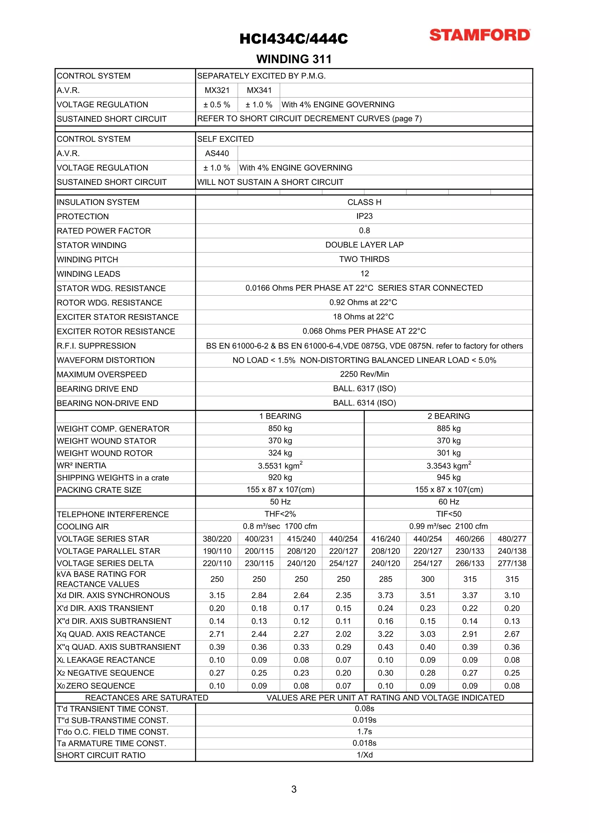
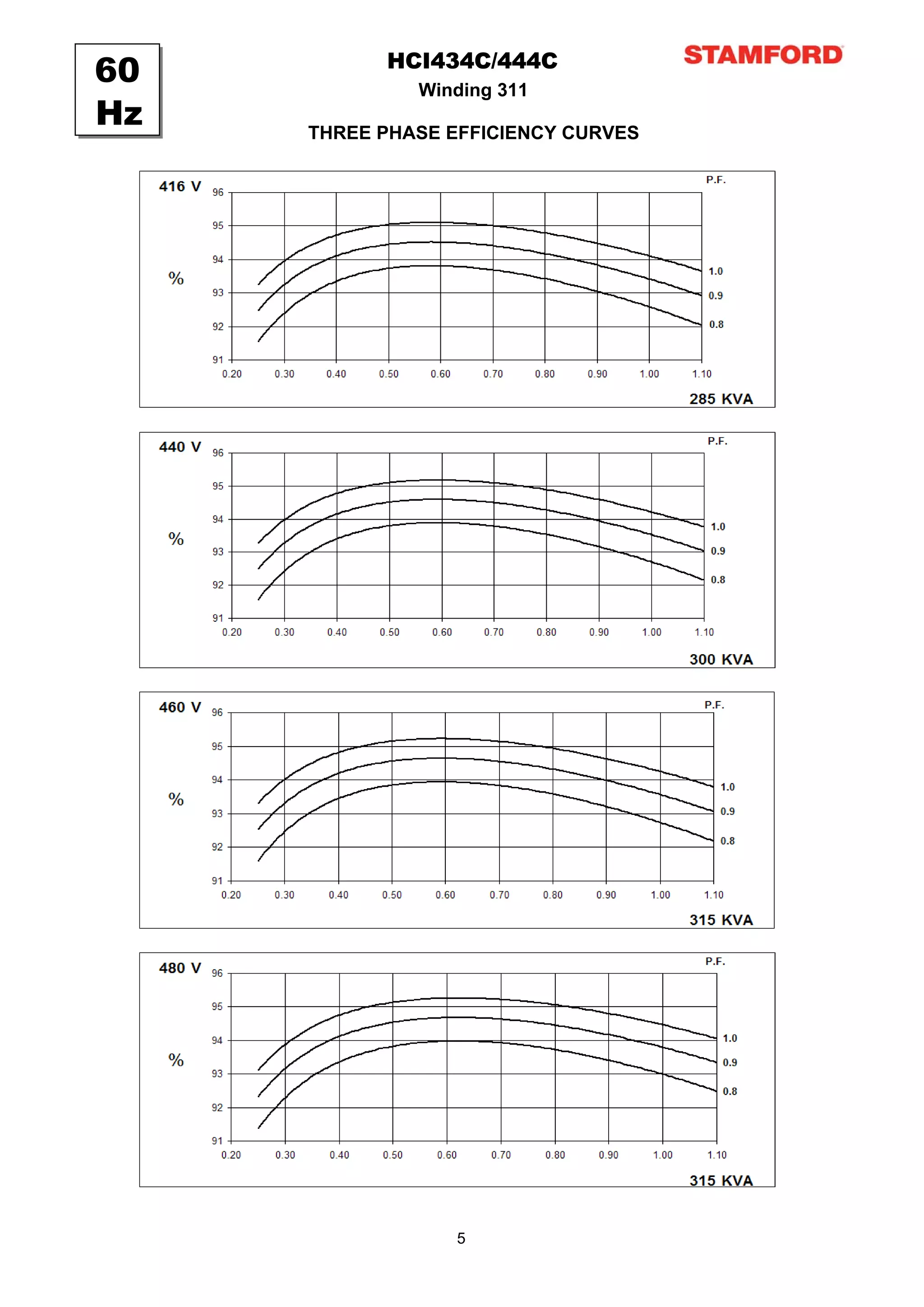
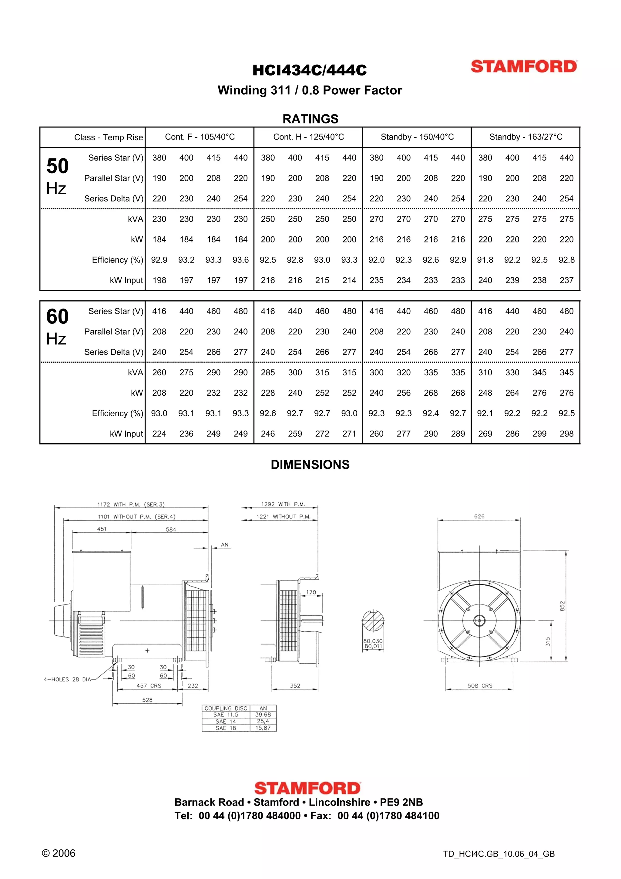
HCI 434C/444C - Technical Data Sheet
HCI434C/444C
                                       SPECIFICATIONS & OPTIONS


STANDARDS                                                    WINDINGS & ELECTRICAL PERFORMANCE
Newage Stamford industrial generators meet the               All generator stators are wound to 2/3 pitch. This
requirements of BS EN 60034 and the relevant section         eliminates triplen (3rd, 9th, 15th …) harmonics on the
of other international standards such as BS5000, VDE         voltage waveform and is found to be the optimum
0530, NEMA MG1-32, IEC34, CSA C22.2-100, AS1359.             design for trouble-free supply of non-linear loads. The
Other standards and certifications can be considered on      2/3 pitch design avoids excessive neutral currents
request.                                                     sometimes seen with higher winding pitches, when in
                                                             parallel with the mains. A fully connected damper
VOLTAGE REGULATORS                                           winding reduces oscillations during paralleling. This
                                                             winding, with the 2/3 pitch and carefully selected pole
AS440 AVR - STANDARD                                         and tooth designs, ensures very low waveform
With this self-excited system the main stator provides       distortion.
power via the Automatic Voltage Regulator (AVR) to the
exciter stator. The high efficiency semi-conductors of       TERMINALS & TERMINAL BOX
the AVR ensure positive build-up from initial low levels     Standard generators are 3-phase reconnectable with 12
of residual voltage.                                         ends brought out to the terminals, which are mounted
The exciter rotor output is fed to the main rotor through    on a cover at the non-drive end of the generator. A
a three-phase full-wave bridge rectifier. The rectifier is   sheet steel terminal box contains the AVR and provides
protected by a surge suppressor against surges               ample space for the customers' wiring and gland
caused, for example, by short circuit or out-of-phase        arrangements. It has removable panels for easy
paralleling.                                                 access.
The AS440 will support a range of electronic
accessories, including a 'droop' Current Transformer         SHAFT & KEYS
(CT) to permit parallel operation with other ac              All generator rotors are dynamically balanced to better
generators.                                                  than BS6861:Part 1 Grade 2.5 for minimum vibration in
                                                             operation. Two bearing generators are balanced with a
MX341 AVR                                                    half key.
This sophisticated AVR is incorporated into the
Stamford Permanent Magnet Generator (PMG) control            INSULATION/IMPREGNATION
system.                                                      The insulation system is class 'H'.
The PMG provides power via the AVR to the main               All wound components are impregnated with materials
exciter, giving a source of constant excitation power        and processes designed specifically to provide the high
independent of generator output. The main exciter            build required for static windings and the high
output is then fed to the main rotor, through a full wave    mechanical strength required for rotating components.
bridge, protected by a surge suppressor. The AVR has
in-built protection against sustained over-excitation,       QUALITY ASSURANCE
caused by internal or external faults. This de-excites       Generators are manufactured using production
the machine after a minimum of 5 seconds.                    procedures having a quality assurance level to BS EN
An engine relief load acceptance feature can enable full     ISO 9001.
load to be applied to the generator in a single step.
If three-phase sensing is required with the PMG system       The stated voltage regulation may not be maintained in
the MX321 AVR must be used.                                  the presence of certain radio transmitted signals. Any
We recommend three-phase sensing for applications            change in performance will fall within the limits of
with greatly unbalanced or highly non-linear loads.          Criteria 'B' of EN 61000-6-2:2001. At no time will the
                                                             steady-state voltage regulation exceed 2%.
MX321 AVR
The most sophisticated of all our AVRs combines all the
features of the MX341 with, additionally, three-phase
rms sensing, for improved regulation and performance.
Over voltage protection is built-in and short circuit
current level adjustments is an optional facility.           NB Continuous development of our products entitles us
                                                             to change specification details without notice, therefore
                                                             they must not be regarded as binding.

                                                             Front cover drawing typical of product range.


                                                             2
HCI434C/444C
                                               WINDING 311
CONTROL SYSTEM                 SEPARATELY EXCITED BY P.M.G.
A.V.R.                          MX321        MX341
VOLTAGE REGULATION              ± 0.5 %     ± 1.0 %     With 4% ENGINE GOVERNING
SUSTAINED SHORT CIRCUIT        REFER TO SHORT CIRCUIT DECREMENT CURVES (page 7)

CONTROL SYSTEM                 SELF EXCITED
A.V.R.                          AS440
VOLTAGE REGULATION              ± 1.0 %    With 4% ENGINE GOVERNING
SUSTAINED SHORT CIRCUIT        WILL NOT SUSTAIN A SHORT CIRCUIT

INSULATION SYSTEM                                                          CLASS H
PROTECTION                                                                     IP23
RATED POWER FACTOR                                                               0.8
STATOR WINDING                                                        DOUBLE LAYER LAP
WINDING PITCH                                                            TWO THIRDS
WINDING LEADS                                                                    12
STATOR WDG. RESISTANCE                      0.0166 Ohms PER PHASE AT 22°C SERIES STAR CONNECTED
ROTOR WDG. RESISTANCE                                                  0.92 Ohms at 22°C
EXCITER STATOR RESISTANCE                                              18 Ohms at 22°C
EXCITER ROTOR RESISTANCE                                         0.068 Ohms PER PHASE AT 22°C
R.F.I. SUPPRESSION              BS EN 61000-6-2 & BS EN 61000-6-4,VDE 0875G, VDE 0875N. refer to factory for others
WAVEFORM DISTORTION                       NO LOAD < 1.5% NON-DISTORTING BALANCED LINEAR LOAD < 5.0%
MAXIMUM OVERSPEED                                                        2250 Rev/Min
BEARING DRIVE END                                                      BALL. 6317 (ISO)
BEARING NON-DRIVE END                                                  BALL. 6314 (ISO)
                                                1 BEARING                                            2 BEARING
WEIGHT COMP. GENERATOR                               850 kg                                               885 kg
WEIGHT WOUND STATOR                                  370 kg                                               370 kg
WEIGHT WOUND ROTOR                                   324 kg                                               301 kg
WR² INERTIA                                    3.5531 kgm2                                           3.3543 kgm2
SHIPPING WEIGHTS in a crate                       920 kg                                                945 kg
PACKING CRATE SIZE                          155 x 87 x 107(cm)                                    155 x 87 x 107(cm)
                                                     50 Hz                                                60 Hz
TELEPHONE INTERFERENCE                           THF<2%                                                   TIF<50
COOLING AIR                                 0.8 m³/sec 1700 cfm                                  0.99 m³/sec 2100 cfm
VOLTAGE SERIES STAR             380/220     400/231      415/240       440/254         416/240    440/254     460/266     480/277
VOLTAGE PARALLEL STAR           190/110     200/115      208/120       220/127         208/120    220/127     230/133     240/138
VOLTAGE SERIES DELTA            220/110     230/115      240/120       254/127         240/120    254/127     266/133     277/138
kVA BASE RATING FOR
                                 250          250             250       250             285         300            315     315
REACTANCE VALUES
Xd DIR. AXIS SYNCHRONOUS         3.15         2.84            2.64      2.35            3.73       3.51            3.37    3.10
X'd DIR. AXIS TRANSIENT          0.20         0.18            0.17      0.15            0.24       0.23            0.22    0.20
X''d DIR. AXIS SUBTRANSIENT      0.14         0.13            0.12      0.11            0.16       0.15            0.14    0.13
Xq QUAD. AXIS REACTANCE          2.71         2.44            2.27      2.02            3.22       3.03            2.91    2.67
X''q QUAD. AXIS SUBTRANSIENT     0.39         0.36            0.33      0.29            0.43       0.40            0.39    0.36
XL LEAKAGE REACTANCE             0.10         0.09            0.08      0.07            0.10       0.09            0.09    0.08
X2 NEGATIVE SEQUENCE             0.27         0.25            0.23      0.20            0.30       0.28            0.27    0.25
X0 ZERO SEQUENCE                 0.10         0.09     0.08     0.07        0.10   0.09     0.09     0.08
        REACTANCES ARE SATURATED                  VALUES ARE PER UNIT AT RATING AND VOLTAGE INDICATED
T'd TRANSIENT TIME CONST.                                             0.08s
T''d SUB-TRANSTIME CONST.                                            0.019s
T'do O.C. FIELD TIME CONST.                                           1.7s
Ta ARMATURE TIME CONST.                                              0.018s
SHORT CIRCUIT RATIO                                                   1/Xd


                                                             3
HCI434C/444C
50            Winding 311
Hz   THREE PHASE EFFICIENCY CURVES


                  4
HCI434C/444C
60            Winding 311
Hz   THREE PHASE EFFICIENCY CURVES


                  5
HCI434C/444C
                                                                                                                                                    Winding 311

                                                                                                              Locked Rotor Motor Starting Curve


                                                                                                                                                            50
                                                                                                                                                              Hz
                                                                                          MX                                                                                                                                                                SX
                                                                                                      346V          380V 400V 415V 440V                                                                                                                          346V           380V     400V 415V                        440V
                                                      30                                                                                                                                                                 30


                                                      25                                                                                                                                                                 25


                                                      20                                                                                                                                                                 20


                                                                                                                                                                   P E R C E N T T R A N S IE N T V O L T A G E D IP .
P E R C E N T T R A N S IE N T V O L T A G E D IP .


                                                      15                                                                                                                                                                 15


                                                      10                                                                                                                                                                 10


                                                       5                                                                                                                                                                  5


                                                       0                                                                                                                                                                  0
                                                           0   100    200     300         400         500           600          700           800      900                                                                   0    100         200         300           400             500                600            700
                                                                                          LOCKED ROTOR kVA                                                                                                                                                  LOCKED ROTOR kVA


                                                                                                                                                            60
                                                                                                                                                              Hz
                                                                                          MX                                                                                                                                                               SX
                                                                                                             380V         416V         440V   460V   480V                                                                                                        380V          416V    440V          460V          480V
                                                      30                                                                                                                                                                 30


                                                      25                                                                                                                                                                 25


                                                      20                                                                                                                                                                 20
                                                                                                                                                                   P E R C E N T T R A N S IE N T V O L T A G E D IP .
P E R C E N T T R A N S IE N T V O L T A G E D IP .


                                                      15                                                                                                                                                                 15


                                                      10                                                                                                                                                                 10


                                                       5                                                                                                                                                                  5


                                                       0                                                                                                                                                                  0
                                                           0    100     200         300         400           500            600              700       800                                                                   0   100    200         300          400           500            600           700           800
                                                                                          LOCKED ROTOR kVA                                                                                                                                                  LOCKED ROTOR kVA


                                                                                                                                                              6
HCI434C

    Three-phase Short Circuit Decrement Curve. No-load Excitation at Rated Speed
                          Based on star (wye) connection.
 50
 Hz
                      10000


                                                                                                      SYMMETRICAL

                                                                                                      ASYMMETRICAL
                CURRE NT (Am ps)


                                   1000


                                   100
                                     0.001                 0.01              0.1                  1                          10
                                                                          TIME (secs)


             Sustained Short Circuit = 1,100 Amps

  60               10000
  Hz
                                                                                                      SYMMETRICAL

                                                                                                      ASYMMETRICAL
              CURRE NT (Am ps)


                                 1000


                                   100
                                     0.001                 0.01              0.1                  1                          10
                                                                          TIME (secs)


             Sustained Short Circuit = 1,200 Amps
 Note 1                                                            Note 2
 The following multiplication factors should be                    The following multiplication factor should be used to convert the
 used to adjust the values from curve between                      values calculated in accordance with NOTE 1 to those applicable
 time 0.001 seconds and the minimum current                        to the various types of short circuit :
 point in respect of nominal operating voltage :
         50Hz                                      60Hz                                               3-phase        2-phase L-L 1-phase L-N
  Voltage                   Factor           Voltage      Factor   Instantaneous                        x 1.00     x 0.87    x 1.30
   380v                     X 1.00            416v        X 1.00   Minimum                              x 1.00     x 1.80    x 3.20
   400v                     X 1.05            440v        X 1.06   Sustained                            x 1.00     x 1.50    x 2.50
   415v                     X 1.09            460v        X 1.10   Max. sustained duration              10 sec.    5 sec.    2 sec.
   440v                     X 1.16            480v        X 1.15                       All other times are unchanged
The sustained current value is constant irrespective                Note 3
of voltage level                                                    Curves are drawn for Star (Wye) connected machines. For other
                                                                    connection the following multipliers should be applied to current
                                                                    values as shown :
                                                                    Parallel Star = Curve current value X 2


                                                                           7
HCI434C/444C
                                             Winding 311 / 0.8 Power Factor

                                                               RATINGS
     Class - Temp Rise         Cont. F - 105/40°C          Cont. H - 125/40°C          Standby - 150/40°C           Standby - 163/27°C

          Series Star (V)    380    400   415    440    380    400    415    440    380    400    415     440    380    400    415    440
50       Parallel Star (V)   190    200   208    220    190    200    208    220    190    200    208     220    190    200    208    220
Hz       Series Delta (V)    220    230   240    254    220    230    240    254    220    230    240     254    220    230    240    254

                     kVA     230    230   230    230    250    250    250    250    270    270    270     270    275    275    275    275

                      kW     184    184   184    184    200    200    200    200    216    216    216     216    220    220    220    220

           Efficiency (%) 92.9     93.2   93.3   93.6   92.5   92.8   93.0   93.3   92.0   92.3   92.6    92.9   91.8   92.2   92.5   92.8

                kW Input     198    197   197    197    216    216    215    214    235    234    233     233    240    239    238    237


          Series Star (V)    416    440   460    480    416    440    460    480    416    440    460     480    416    440    460    480
60
         Parallel Star (V)   208    220   230    240    208    220    230    240    208    220    230     240    208    220    230    240
Hz
         Series Delta (V)    240    254   266    277    240    254    266    277    240    254    266     277    240    254    266    277

                     kVA     260    275   290    290    285    300    315    315    300    320    335     335    310    330    345    345

                      kW     208    220   232    232    228    240    252    252    240    256    268     268    248    264    276    276

           Efficiency (%) 93.0     93.1   93.1   93.3   92.6   92.7   92.7   93.0   92.3   92.3   92.4    92.7   92.1   92.2   92.2   92.5

                kW Input     224    236   249    249    246    259    272    271    260    277    290     289    269    286    299    298


                                                          DIMENSIONS


                                   Barnack Road • Stamford • Lincolnshire • PE9 2NB
                                   Tel: 00 44 (0)1780 484000 • Fax: 00 44 (0)1780 484100


© 2006                                                                                                   TD_HCI4C.GB_10.06_04_GB

Hci4 c

  • 1.
    HCI 434C/444C -Technical Data Sheet
  • 2.
    HCI434C/444C SPECIFICATIONS & OPTIONS STANDARDS WINDINGS & ELECTRICAL PERFORMANCE Newage Stamford industrial generators meet the All generator stators are wound to 2/3 pitch. This requirements of BS EN 60034 and the relevant section eliminates triplen (3rd, 9th, 15th …) harmonics on the of other international standards such as BS5000, VDE voltage waveform and is found to be the optimum 0530, NEMA MG1-32, IEC34, CSA C22.2-100, AS1359. design for trouble-free supply of non-linear loads. The Other standards and certifications can be considered on 2/3 pitch design avoids excessive neutral currents request. sometimes seen with higher winding pitches, when in parallel with the mains. A fully connected damper VOLTAGE REGULATORS winding reduces oscillations during paralleling. This winding, with the 2/3 pitch and carefully selected pole AS440 AVR - STANDARD and tooth designs, ensures very low waveform With this self-excited system the main stator provides distortion. power via the Automatic Voltage Regulator (AVR) to the exciter stator. The high efficiency semi-conductors of TERMINALS & TERMINAL BOX the AVR ensure positive build-up from initial low levels Standard generators are 3-phase reconnectable with 12 of residual voltage. ends brought out to the terminals, which are mounted The exciter rotor output is fed to the main rotor through on a cover at the non-drive end of the generator. A a three-phase full-wave bridge rectifier. The rectifier is sheet steel terminal box contains the AVR and provides protected by a surge suppressor against surges ample space for the customers' wiring and gland caused, for example, by short circuit or out-of-phase arrangements. It has removable panels for easy paralleling. access. The AS440 will support a range of electronic accessories, including a 'droop' Current Transformer SHAFT & KEYS (CT) to permit parallel operation with other ac All generator rotors are dynamically balanced to better generators. than BS6861:Part 1 Grade 2.5 for minimum vibration in operation. Two bearing generators are balanced with a MX341 AVR half key. This sophisticated AVR is incorporated into the Stamford Permanent Magnet Generator (PMG) control INSULATION/IMPREGNATION system. The insulation system is class 'H'. The PMG provides power via the AVR to the main All wound components are impregnated with materials exciter, giving a source of constant excitation power and processes designed specifically to provide the high independent of generator output. The main exciter build required for static windings and the high output is then fed to the main rotor, through a full wave mechanical strength required for rotating components. bridge, protected by a surge suppressor. The AVR has in-built protection against sustained over-excitation, QUALITY ASSURANCE caused by internal or external faults. This de-excites Generators are manufactured using production the machine after a minimum of 5 seconds. procedures having a quality assurance level to BS EN An engine relief load acceptance feature can enable full ISO 9001. load to be applied to the generator in a single step. If three-phase sensing is required with the PMG system The stated voltage regulation may not be maintained in the MX321 AVR must be used. the presence of certain radio transmitted signals. Any We recommend three-phase sensing for applications change in performance will fall within the limits of with greatly unbalanced or highly non-linear loads. Criteria 'B' of EN 61000-6-2:2001. At no time will the steady-state voltage regulation exceed 2%. MX321 AVR The most sophisticated of all our AVRs combines all the features of the MX341 with, additionally, three-phase rms sensing, for improved regulation and performance. Over voltage protection is built-in and short circuit current level adjustments is an optional facility. NB Continuous development of our products entitles us to change specification details without notice, therefore they must not be regarded as binding. Front cover drawing typical of product range. 2
  • 3.
    HCI434C/444C WINDING 311 CONTROL SYSTEM SEPARATELY EXCITED BY P.M.G. A.V.R. MX321 MX341 VOLTAGE REGULATION ± 0.5 % ± 1.0 % With 4% ENGINE GOVERNING SUSTAINED SHORT CIRCUIT REFER TO SHORT CIRCUIT DECREMENT CURVES (page 7) CONTROL SYSTEM SELF EXCITED A.V.R. AS440 VOLTAGE REGULATION ± 1.0 % With 4% ENGINE GOVERNING SUSTAINED SHORT CIRCUIT WILL NOT SUSTAIN A SHORT CIRCUIT INSULATION SYSTEM CLASS H PROTECTION IP23 RATED POWER FACTOR 0.8 STATOR WINDING DOUBLE LAYER LAP WINDING PITCH TWO THIRDS WINDING LEADS 12 STATOR WDG. RESISTANCE 0.0166 Ohms PER PHASE AT 22°C SERIES STAR CONNECTED ROTOR WDG. RESISTANCE 0.92 Ohms at 22°C EXCITER STATOR RESISTANCE 18 Ohms at 22°C EXCITER ROTOR RESISTANCE 0.068 Ohms PER PHASE AT 22°C R.F.I. SUPPRESSION BS EN 61000-6-2 & BS EN 61000-6-4,VDE 0875G, VDE 0875N. refer to factory for others WAVEFORM DISTORTION NO LOAD < 1.5% NON-DISTORTING BALANCED LINEAR LOAD < 5.0% MAXIMUM OVERSPEED 2250 Rev/Min BEARING DRIVE END BALL. 6317 (ISO) BEARING NON-DRIVE END BALL. 6314 (ISO) 1 BEARING 2 BEARING WEIGHT COMP. GENERATOR 850 kg 885 kg WEIGHT WOUND STATOR 370 kg 370 kg WEIGHT WOUND ROTOR 324 kg 301 kg WR² INERTIA 3.5531 kgm2 3.3543 kgm2 SHIPPING WEIGHTS in a crate 920 kg 945 kg PACKING CRATE SIZE 155 x 87 x 107(cm) 155 x 87 x 107(cm) 50 Hz 60 Hz TELEPHONE INTERFERENCE THF<2% TIF<50 COOLING AIR 0.8 m³/sec 1700 cfm 0.99 m³/sec 2100 cfm VOLTAGE SERIES STAR 380/220 400/231 415/240 440/254 416/240 440/254 460/266 480/277 VOLTAGE PARALLEL STAR 190/110 200/115 208/120 220/127 208/120 220/127 230/133 240/138 VOLTAGE SERIES DELTA 220/110 230/115 240/120 254/127 240/120 254/127 266/133 277/138 kVA BASE RATING FOR 250 250 250 250 285 300 315 315 REACTANCE VALUES Xd DIR. AXIS SYNCHRONOUS 3.15 2.84 2.64 2.35 3.73 3.51 3.37 3.10 X'd DIR. AXIS TRANSIENT 0.20 0.18 0.17 0.15 0.24 0.23 0.22 0.20 X''d DIR. AXIS SUBTRANSIENT 0.14 0.13 0.12 0.11 0.16 0.15 0.14 0.13 Xq QUAD. AXIS REACTANCE 2.71 2.44 2.27 2.02 3.22 3.03 2.91 2.67 X''q QUAD. AXIS SUBTRANSIENT 0.39 0.36 0.33 0.29 0.43 0.40 0.39 0.36 XL LEAKAGE REACTANCE 0.10 0.09 0.08 0.07 0.10 0.09 0.09 0.08 X2 NEGATIVE SEQUENCE 0.27 0.25 0.23 0.20 0.30 0.28 0.27 0.25 X0 ZERO SEQUENCE 0.10 0.09 0.08 0.07 0.10 0.09 0.09 0.08 REACTANCES ARE SATURATED VALUES ARE PER UNIT AT RATING AND VOLTAGE INDICATED T'd TRANSIENT TIME CONST. 0.08s T''d SUB-TRANSTIME CONST. 0.019s T'do O.C. FIELD TIME CONST. 1.7s Ta ARMATURE TIME CONST. 0.018s SHORT CIRCUIT RATIO 1/Xd 3
  • 4.
    HCI434C/444C 50 Winding 311 Hz THREE PHASE EFFICIENCY CURVES 4
  • 5.
    HCI434C/444C 60 Winding 311 Hz THREE PHASE EFFICIENCY CURVES 5
  • 6.
    HCI434C/444C Winding 311 Locked Rotor Motor Starting Curve 50 Hz MX SX 346V 380V 400V 415V 440V 346V 380V 400V 415V 440V 30 30 25 25 20 20 P E R C E N T T R A N S IE N T V O L T A G E D IP . P E R C E N T T R A N S IE N T V O L T A G E D IP . 15 15 10 10 5 5 0 0 0 100 200 300 400 500 600 700 800 900 0 100 200 300 400 500 600 700 LOCKED ROTOR kVA LOCKED ROTOR kVA 60 Hz MX SX 380V 416V 440V 460V 480V 380V 416V 440V 460V 480V 30 30 25 25 20 20 P E R C E N T T R A N S IE N T V O L T A G E D IP . P E R C E N T T R A N S IE N T V O L T A G E D IP . 15 15 10 10 5 5 0 0 0 100 200 300 400 500 600 700 800 0 100 200 300 400 500 600 700 800 LOCKED ROTOR kVA LOCKED ROTOR kVA 6
  • 7.
    HCI434C Three-phase Short Circuit Decrement Curve. No-load Excitation at Rated Speed Based on star (wye) connection. 50 Hz 10000 SYMMETRICAL ASYMMETRICAL CURRE NT (Am ps) 1000 100 0.001 0.01 0.1 1 10 TIME (secs) Sustained Short Circuit = 1,100 Amps 60 10000 Hz SYMMETRICAL ASYMMETRICAL CURRE NT (Am ps) 1000 100 0.001 0.01 0.1 1 10 TIME (secs) Sustained Short Circuit = 1,200 Amps Note 1 Note 2 The following multiplication factors should be The following multiplication factor should be used to convert the used to adjust the values from curve between values calculated in accordance with NOTE 1 to those applicable time 0.001 seconds and the minimum current to the various types of short circuit : point in respect of nominal operating voltage : 50Hz 60Hz 3-phase 2-phase L-L 1-phase L-N Voltage Factor Voltage Factor Instantaneous x 1.00 x 0.87 x 1.30 380v X 1.00 416v X 1.00 Minimum x 1.00 x 1.80 x 3.20 400v X 1.05 440v X 1.06 Sustained x 1.00 x 1.50 x 2.50 415v X 1.09 460v X 1.10 Max. sustained duration 10 sec. 5 sec. 2 sec. 440v X 1.16 480v X 1.15 All other times are unchanged The sustained current value is constant irrespective Note 3 of voltage level Curves are drawn for Star (Wye) connected machines. For other connection the following multipliers should be applied to current values as shown : Parallel Star = Curve current value X 2 7
  • 8.
    HCI434C/444C Winding 311 / 0.8 Power Factor RATINGS Class - Temp Rise Cont. F - 105/40°C Cont. H - 125/40°C Standby - 150/40°C Standby - 163/27°C Series Star (V) 380 400 415 440 380 400 415 440 380 400 415 440 380 400 415 440 50 Parallel Star (V) 190 200 208 220 190 200 208 220 190 200 208 220 190 200 208 220 Hz Series Delta (V) 220 230 240 254 220 230 240 254 220 230 240 254 220 230 240 254 kVA 230 230 230 230 250 250 250 250 270 270 270 270 275 275 275 275 kW 184 184 184 184 200 200 200 200 216 216 216 216 220 220 220 220 Efficiency (%) 92.9 93.2 93.3 93.6 92.5 92.8 93.0 93.3 92.0 92.3 92.6 92.9 91.8 92.2 92.5 92.8 kW Input 198 197 197 197 216 216 215 214 235 234 233 233 240 239 238 237 Series Star (V) 416 440 460 480 416 440 460 480 416 440 460 480 416 440 460 480 60 Parallel Star (V) 208 220 230 240 208 220 230 240 208 220 230 240 208 220 230 240 Hz Series Delta (V) 240 254 266 277 240 254 266 277 240 254 266 277 240 254 266 277 kVA 260 275 290 290 285 300 315 315 300 320 335 335 310 330 345 345 kW 208 220 232 232 228 240 252 252 240 256 268 268 248 264 276 276 Efficiency (%) 93.0 93.1 93.1 93.3 92.6 92.7 92.7 93.0 92.3 92.3 92.4 92.7 92.1 92.2 92.2 92.5 kW Input 224 236 249 249 246 259 272 271 260 277 290 289 269 286 299 298 DIMENSIONS Barnack Road • Stamford • Lincolnshire • PE9 2NB Tel: 00 44 (0)1780 484000 • Fax: 00 44 (0)1780 484100 © 2006 TD_HCI4C.GB_10.06_04_GB