Download to read offline

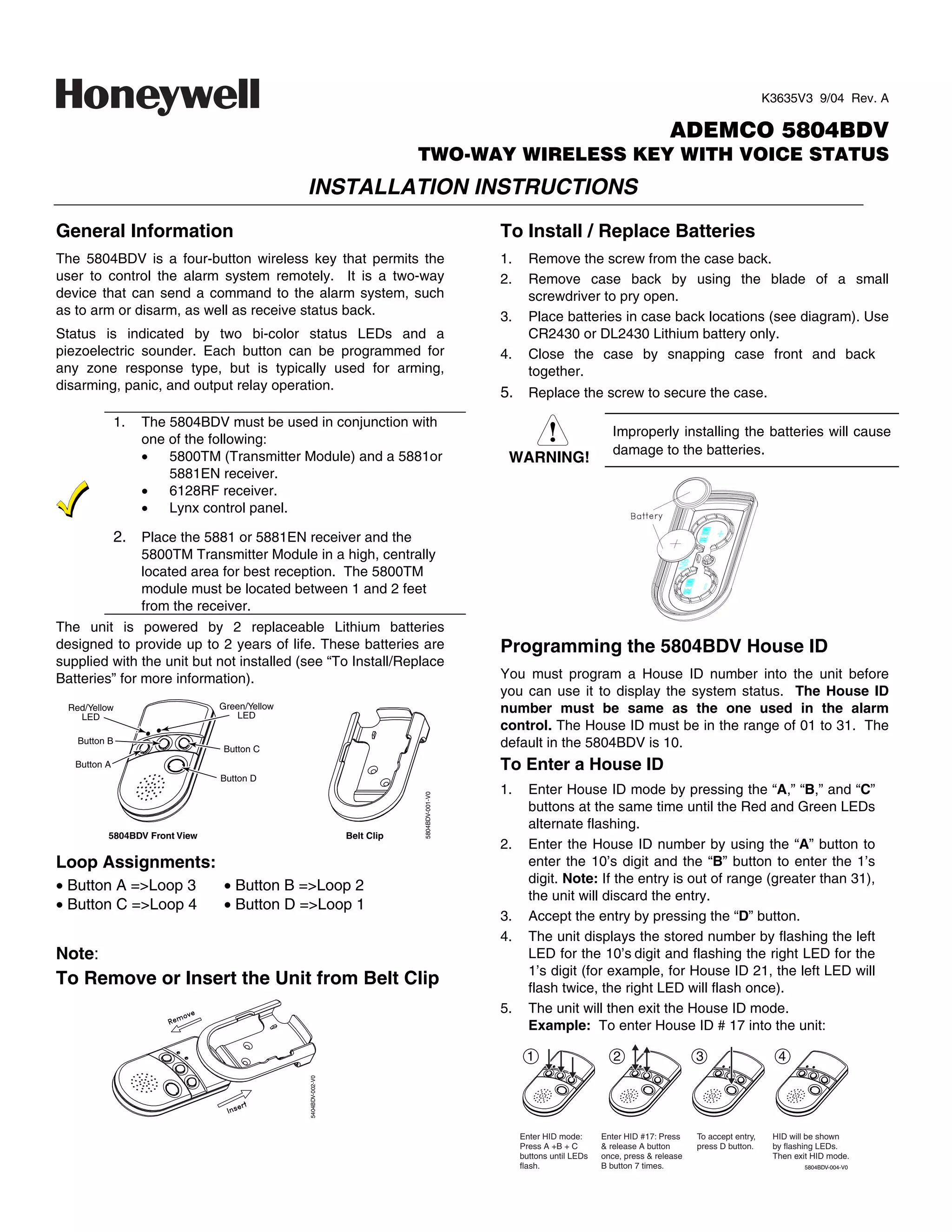
![To View the House ID 2. Answer Yes or No to the “Open/Close Report?” question.
3. Answer Yes to the “RF Button?” question.
1. Enter House ID mode as described in step 1 (previous
page). 4. Enter the zone number assigned to the Arm/Disarm
button. The keypad will show the summary of user
2. Depress the “D” button to view.
information on its display.
3. The unit will display the stored number as described in 5. Test the Arm/Disarm button to make sure it operates
step 4 (previous page). The unit will then exit House ID correctly.
mode.
Programming a House ID in the Alarm Adjusting Volume Level
Control This unit is shipped with the volume set to the lowest level. To
adjust the volume, proceed as follows:
• On VISTA-40, 50P, 100, and above, use Device
1. Enter the Volume Level Programming mode by pressing
Programming mode to enable the RF receiver and enter
and holding the “A”, “B”, and “D” buttons simultaneously
the House ID number.
until the unit’s red and green LEDs flash alternately.
• On VIA-30PSE, VISTA-20SE, and below, go to field ✶24 Note that if no button is pressed for 5 seconds the unit
and enter the House ID number. will automatically shut down and no change to the volume
Programming the Buttons level is made.
Each 5804BDV is assigned a unique serial number during a. Press the “A” button for low volume level, or
manufacture. Each button on the unit also has a unique b. Press the “B” button for medium volume level, or
“loop” number that must be programmed into the alarm control c. Press the “C” button for maximum volume level. The
during installation. Assign each button to an individual zone word “Alarm” will be heard at the volume level
number and program the Input Type as “BR” (Button Type selected.
RF) by entering “5” in the control’s Zone Programming mode. 2. Press the “D” to accept.
Then, input the serial number by one of the following Volume level affects the life of the battery. Use low
methods: volume for maximum battery life.
• Transmit twice from the device by pressing one of the
buttons when prompted for the serial number.
Operating the Buttons
• Enter the serial number manually through the keypad.
• Enter the serial number through V-LINK or Compass To Activate a Function
downloader software as applicable. To activate a programmed function, press and hold the
Be sure to include the loop number of each button during associated button down until the yellow LED flashes; then
programming (see loop assignments on previous page). release it.
NOTE: Do not use the 5804BDV for 24-hour silent alarm, as
To Request System Status
the unit itself is not silent. Because the 5804BDV is a two-way device, users can check
Button C the system status before arming or disarming their system. To
check system status, press and release any button
If you choose not to use the “C” button, you must do the
momentarily. The yellow LED will flash after you release the
following to avoid a “Check” condition when the button is
button. After a second or two, the 5804BDV will display the
accidentally pressed:
system status information using a combination of LED and
1. Assign this button to a zone. sounder activity (see the System Status Indications Table). If
2. After the serial number has been programmed, re-enter 5804BDV does not receive system status information from the
Zone Programming for that zone. panel for approximately 5 seconds, it will shut itself down. It
3. At the “Zone Type” prompt, enter 00 and press [✶]. will also shut itself down if there is no button activity within 5
a) On VIA-30 controls and below, the system will ask seconds of receiving a status update.
whether you want to permanently delete that zone. This device may not receive the system
Enter 0 (No). This will cause the system to retain the
serial number, but render the button inactive. status properly if it operates within a few feet
of the 5881 RF receiver.
b) On VISTA-40 and above, continue to press [✶] until WARNING!
you see the “Enter Zone No?” prompt again. At this
point, Press 00 and [✶]. Then press ✶99 to exit
Program mode.
On VISTA-40 and Above
If a button is assigned to zone type 20 (Arm Stay), 21 (Arm
Away), or 22 (Disarm), you must assign a user to the button in
order for it to operate.
To assign a user number to the Arm/Disarm button:
1. Enter [4-digit User Code] + 8 + [User No.] + [4-digit new
User Code].
–2–](https://image.slidesharecdn.com/honeywell-5804bdv-install-guide-120804183911-phpapp01/85/Honeywell-5804bdv-install-guide-2-320.jpg)
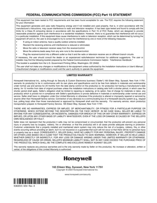
![System Status Indications Table
LED LED Condition Speech System Status
Red On Steady System Armed Away Armed Away or Maximum
System Armed Stay Armed Stay or Instant
Flashing Fire Fire Zone (Faulted Zone) Fire Alarm in progress
Alarm Alarm Zone (Faulted Zone) Armed, Burglary Alarm in progress
Alarm Alarm Zone (Faulted Zone) Alarm Memory
Green On Steady System Disarmed Ready To Arm Disarmed, Ready to Arm
Flashing System Disarmed Not Ready To Arm System Not Ready, Zones Faulted
Yellow (Right) Flashing –– Indicates RF transmission
Red Green Alternately –– In Enter House ID Mode
Flashing
In Set Volume Level Mode
N/A N/A System AC Loss AC Loss Condition
Low Battery Low Battery Condition
Multiple Button Operations Low-Battery Indication
When the unit goes into a low battery condition, the yellow
LED will not flash when a button is pressed. Change both
The 5804BDV should not be used for 24-hour
silent alarm, as the unit itself is not silent.
batteries immediately. Refer to instructions in “To
WARNING! Install/Replace Batteries” paragraph on first page.
The 5804BDV can generate the same responses as keypad Specifications
panic key pairs of [✶] + [#] and [✶] + [1] by depressing “A” + “C” Physical: Belt Clip: 4.1H x 2.2”W x 0.8”D
and “B” + “D” button pairs, respectively. Transmitter: 3.9”H x 2.0”W x 0.69”D
You must depress the button pair for at least 2 seconds for the Battery: Maxell CR2430 or Duracell DL2430
5804BDV to recognize the button pair command. These button
pairs allow the user to activate panic, fire, and medical alarms
depending on control panel programming.
A + C Button Pair B + D Button Pair
5804BDV-005-V0
FOR LIMITATIONS OF THE ENTIRE ALARM SYSTEM, REFER TO THE INSTALLATION INSTRUCTIONS FOR THE
CONTROL WITH WHICH THIS DEVICE IS USED.
FCC STATEMENT
This device complies with Part 15 of the FCC rules. Operation is subject to the following two conditions: (1)
This device may not cause harmful interference, and (2) This device must accept any interference received,
including interference that may cause undesired operation.
FCC ID.CFS8DL5804BDV
–3–](https://image.slidesharecdn.com/honeywell-5804bdv-install-guide-120804183911-phpapp01/85/Honeywell-5804bdv-install-guide-3-320.jpg)

1. The 5804BDV is a wireless key fob that allows users to remotely control an alarm system through buttons programmed for arming, disarming, panic, and relay operation. 2. It uses 2 replaceable lithium batteries that provide up to 2 years of battery life. The batteries are installed by removing the back case screw and replacing the batteries. 3. The key fob must have a House ID programmed that matches the alarm system in order to display system status via LED lights and sounds. The House ID is programmed by entering a programming mode and pressing buttons to enter the 2-digit ID number.


