Download to read offline

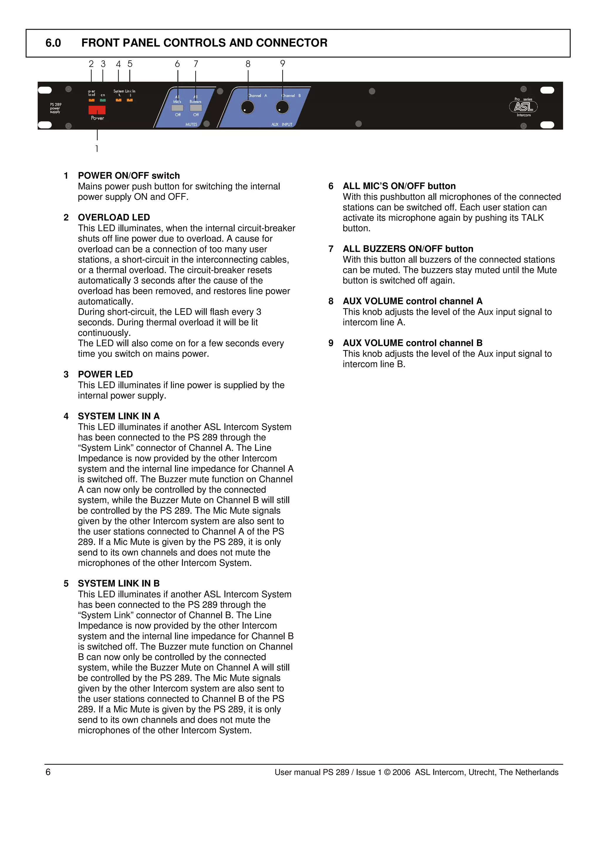
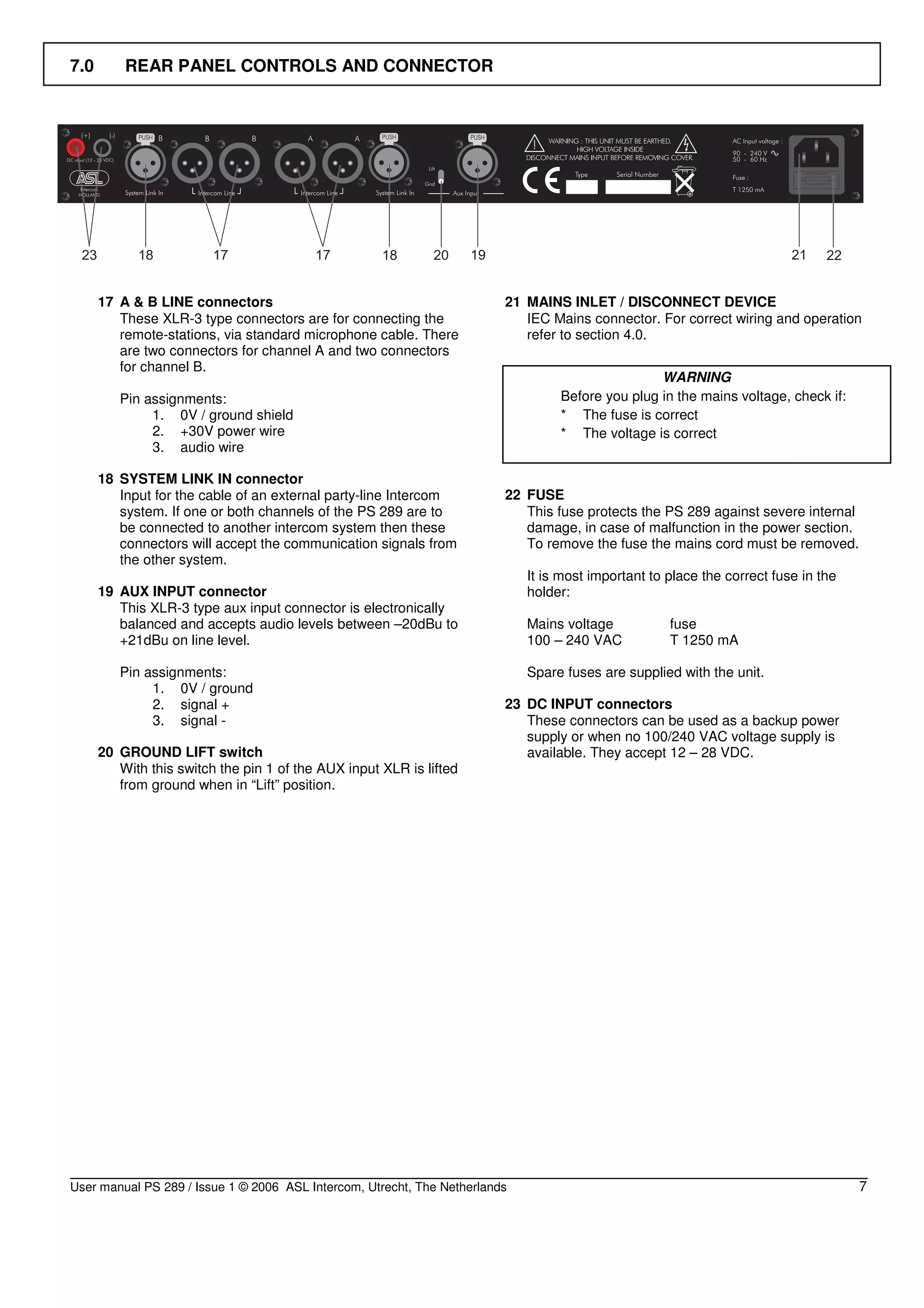
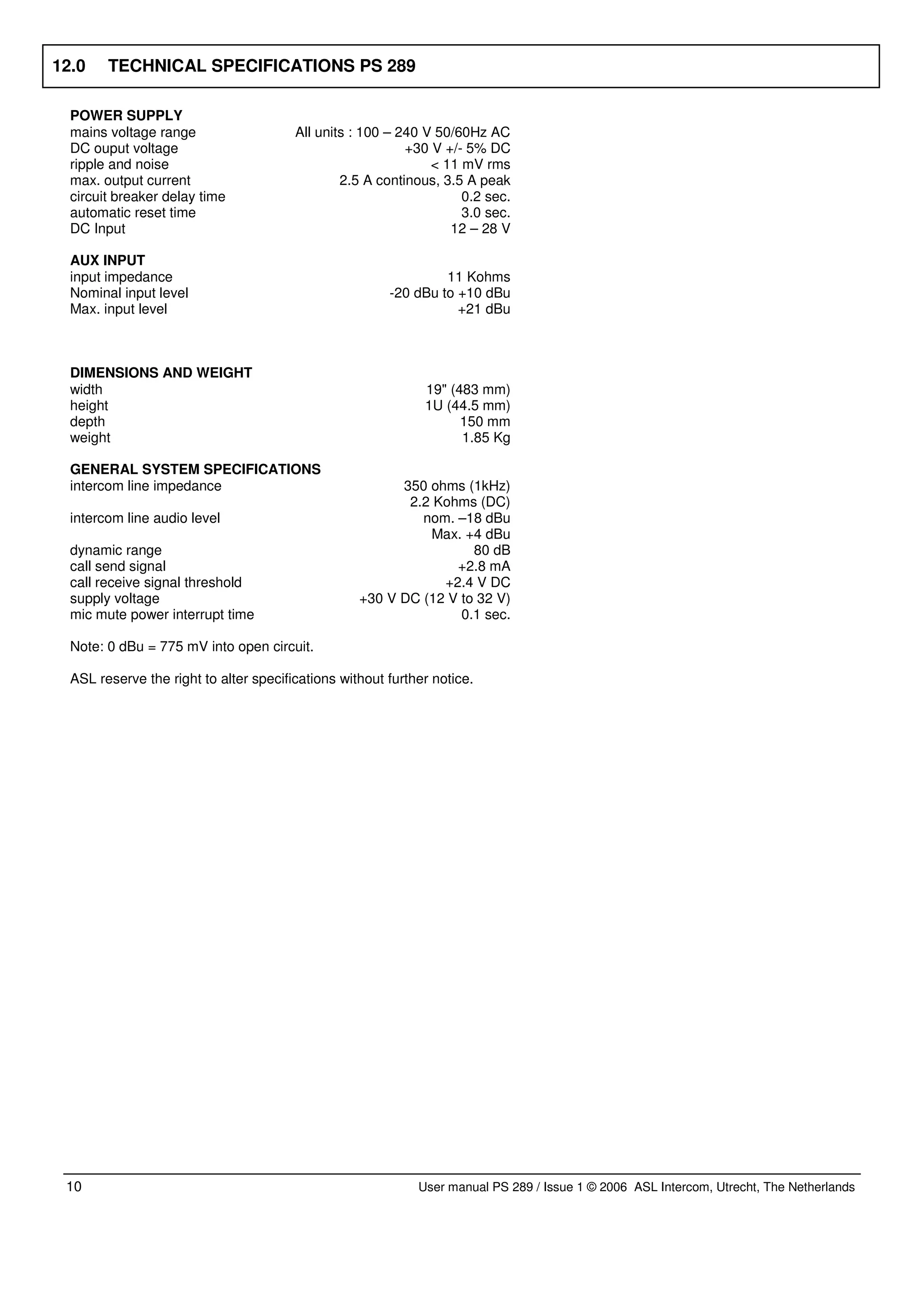


This document is a user manual for the PS 289 dual channel power supply. It contains instructions for safely installing and operating the device, including safety warnings, a general description of the device, instructions for unpacking it, how to install it mechanically in a rack, how to connect the mains power and cabling, operating instructions for front and rear panel controls, warranty information, and technical specifications. It provides all the necessary information for a user to safely set up and use the PS 289 power supply.


![Coded Agents – with UiPath SDK + LangGraph [Virtual Hands-on Workshop]](https://cdn.slidesharecdn.com/ss_thumbnails/codedagentsdeck-251215155422-5497c599-thumbnail.jpg?width=640&height=640&fit=bounds)


![Vibe Coding vs. Spec-Driven Development [Free Meetup]](https://cdn.slidesharecdn.com/ss_thumbnails/vibecodingvsspecdrivendevelopment-251209105622-43f455e7-thumbnail.jpg?width=640&height=640&fit=bounds)
