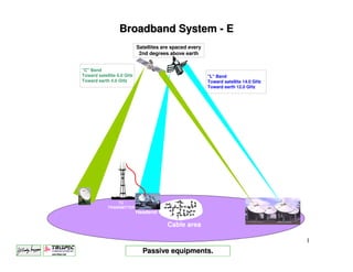
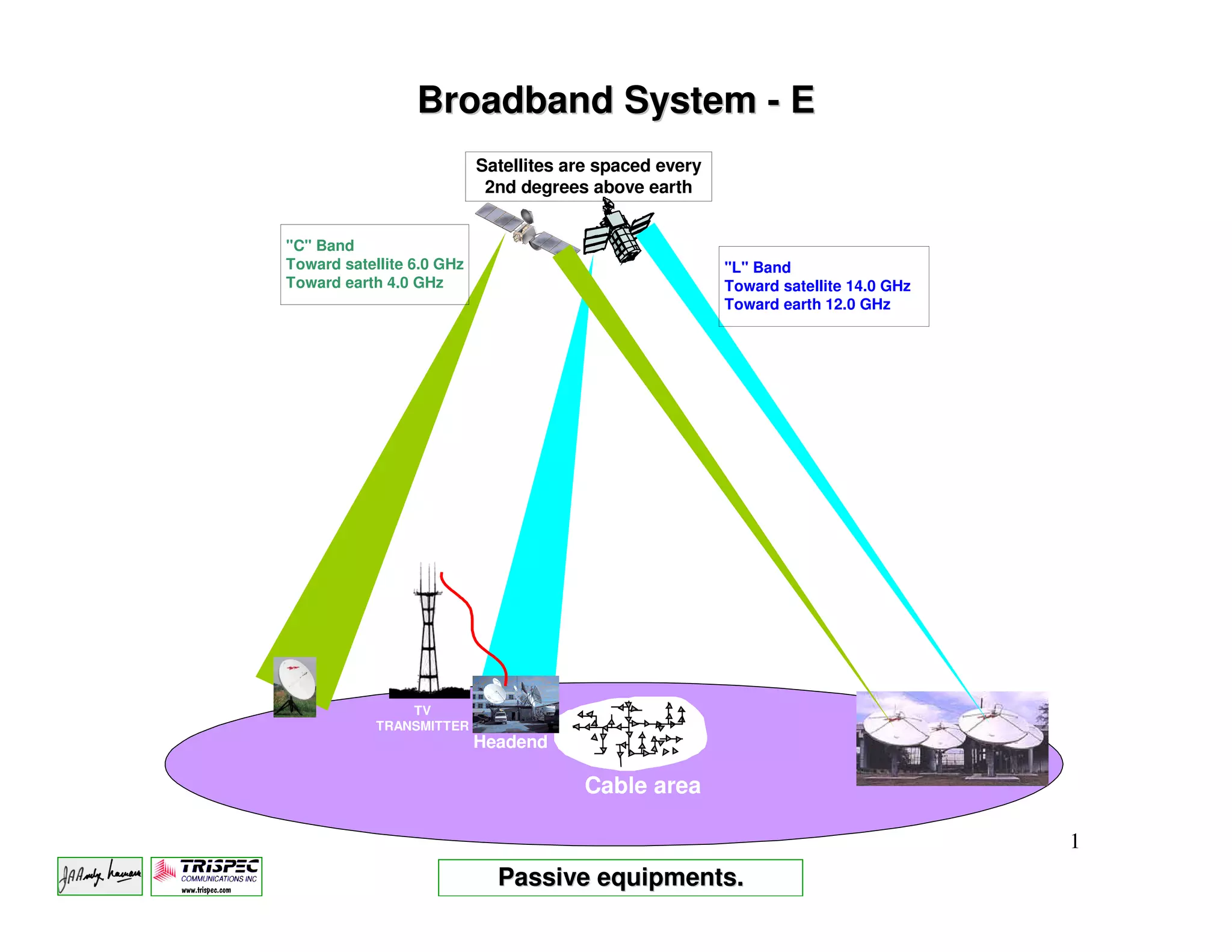
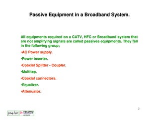
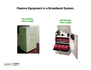
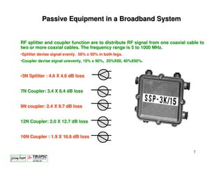
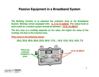
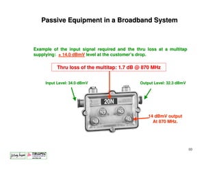
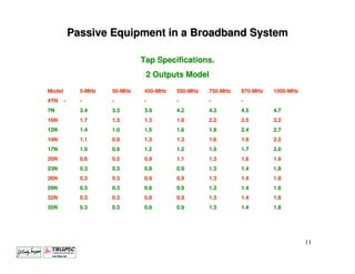
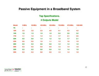
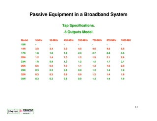
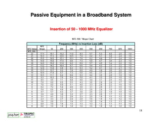
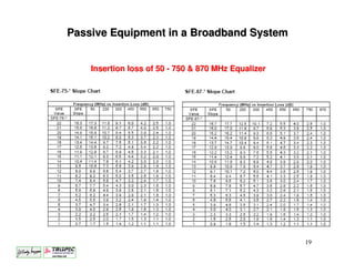
Broadband System - E
                           Satellites are spaced every
                            2nd degrees above earth


"C" Band
Toward satellite 6.0 GHz                                 "L" Band
Toward earth 4.0 GHz                                     Toward satellite 14.0 GHz
                                                         Toward earth 12.0 GHz


                TV
            TRANSMITTER
                           Headend

                                       Cable area

                                                                                     1
                             Passive equipments.
Passive Equipment in a Broadband System.


All equipments required on a CATV, HFC or Broadband system that
are not amplifying signals are called passives equipments. They fall
in the following group;
•AC Power supply.
•Power inserter.
•Coaxial Splitter - Coupler.
•Multitap.
•Coaxial connectors.
•Equalizer.
•Attenuator.


                                                                       2
Passive Equipment in a Broadband System.

POWER SUPPLY.
•The power supply’s function is to convert 110 or 220 Volts AC, 60 Hertz sine wave, to
either 60 or 90 Volts AC 60 Hertz square wave.
•The power supply can transform directly the 110 or 220 VAC supplied by the power
company, to 60 or 90 volts AC. These are called Non-Standby power supply.
• Standby Power Supplies are equipped with 3, 4 or 8 batteries, and keep the
Broadband system operating, when the power company no longer supplied 110 or 220
VAC.
•Stand-by Power Supply comes in two types, UPS or Switch Mode. UPS supplies
voltage to the system at all time, where Switch Mode have a very short delay before
going to battery operation.                             Standby
                                                     Power supply
                  Non standby
                                                           DC
                  Power supply                              to
           90                       90                   90             90-60       90
                        110-220
                180 360   to    0        180   360            180 360   VAC     0        180   360
       0                                             0
                         90-60
                  270    VAC                                   270


                                                                                                     3
Passive Equipment in a Broadband System.


   Non standby
   Power supply              UPS Standby
                             Power supply


                                            4
Passive Equipment in a Broadband System
Standby Power Supply will keep the system operating on standby mode
depending of the following:
•Current draw from the system.
                       system.
•Number of batteries installed.

•The operating temperature.


                                                                      5
                                  Time operating
Passive Equipment in a Broadband System


The Power Inserter is the junction between the coaxial system and the power
supply, it introduce 60 or 90 Volts AC from the Power Supply.
The Power Inserter are usually capable of handling 20 amperes.
Fuses can be installed on each leg for better protection.


                                                                        6
Passive Equipment in a Broadband System


RF splitter and coupler function are to distribute RF signal from one coaxial cable to
two or more coaxial cables. The frequency range is 5 to 1000 MHz.
•Splitter devise signal evenly. 50% x 50% in both legs.
•Coupler devise signal unevenly, 10% x 90%, 20%X80, 40%X60%.


•3N Splitter : 4.6 X 4.6 dB loss


7N Coupler: 3.4 X 8.4 dB loss


9N coupler: 2.4 X 9.7 dB loss


12N Coupler: 2.0 X 12.7 dB loss


16N Coupler : 1.9 X 16.6 dB loss


                                                                                 7
Passive Equipment in a Broadband System

Utilisation of a RF splitter and a RF coupler.

               4.5 dB loss
                   by
                 4.5 dB


                      equal distance
                       from splitter,


               3.5 dB loss
                   by
                 10.9 dB

                                long distance


           short distance


                                                 8
Passive Equipment in a Broadband System


The Multitap function is to attached the customer drop to the Broadband
System. Multitap comes equipped with; 2, 4 or 8 output. The output level at
each outlet on a modern system should be between; 14 to 16 dBmV
The thru loss of a multitap depends on his value, the higher the value of the
multitap, the less is the insertion loss.
They come in the following values:
     35.0, 32.0, 29.0, 26.0, 23.0, 20.0, 17.0, , 14.0, 12.0, 10.5, 10.0, 7.5


          Where the
                                                              14 to 16 dBmV
          customer
         Installation
            goes.


                                                                               9
Passive Equipment in a Broadband System


Example of the input signal required and the thru loss at a multitap
supplying: + 14.0 dBmV level at the customer’s drop.

          Thru loss of the multitap: 1.7 dB @ 870 MHz


     Input Level: 34.0 dBmV                    Output Level: 32.3 dBmV


                                                   14 dBmV output
                                                     At 870 MHz.


                                                                         10
Passive Equipment in a Broadband System

                               Tap Specifications.
                                2 Outputs Model
Model         5-MHz   50-MHz
                      50-      450-MHz
                               450-      550-MHz
                                         550-      750-MHz
                                                   750-      870-MHz
                                                             870-      1000-MHz
                                                                       1000-
4TN     -     -       -        -         -         -         -
7N            3.4     3.3      3.9       4.2       4.3       4.5       4.7
10N           1.7     1.3      1.3       1.8       2.2       2.5       3.2
12N           1.4     1.0      1.5       1.6       1.9       2.4       2.7
14N           1.1     0.9      1.3       1.3       1.6       1.9       2.2
17N           1.0     0.9      1.2       1.2       1.5       1.7       2.0
20N           0.6     0.5      0.9       1.1       1.3       1.6       1.9
23N           0.3     0.3      0.8       0.9       1.3       1.4       1.8
26N           0.3     0.3      0.9       0.9       1.3       1.4       1.8
29N           0.3     0.3      0.8       0.9       1.3       1.4       1.8
32N           0.3     0.3      0.8       0.9       1.3       1.4       1.8
35N           0.3     0.3      0.8       0.9       1.3       1.4       1.8


                                                                                  11
Passive Equipment in a Broadband System

                           Tap Specifications.
                            4 Outputs Model

Model     5-MHz   50-MHz
                  50-      450-MHz
                           450-      550-MHz
                                     550-      750-MHz
                                               750-      870-MHz
                                                         870-      1000-MH
                                                                   1000-
7N        -       -        -         -         -         -         -
10N       3.3     3.3      3.3       4.0       4.1       4.3       4.2
14N       1.6     1.3      1.9       1.9       2.4       2.6       3.2
17N       1.1     1.4      1.3       1.3       1.7       2.1       2.6
20N       0.5     0.9      1.4       1.2       1.5       1.7       2.1
23N       0.6     0.5      1.0       1.1       1.3       1.6       1.9
26N       0.3     0.3      0.8       0.9       1.3       1.4       1.9
29N       0.3     0.3      0.9       0.9       1.3       1.4       1.9
32N       0.3     0.3      0.8       0.9       1.3       1.4       1.9
35N       0.3     0.3      0.8       0.9       1.3       1.4       1.9


                                                                             12
Passive Equipment in a Broadband System

                           Tap Specifications.
                            8 Outputs Model

Model     5-MHz   50-MHz
                  50-      450-MHz
                           450-      550-MHz
                                     550-      750-MHz
                                               750-      870-MHz
                                                         870-      1000-MH
                                                                   1000-
10N       -       -        -         -         -         -         -
14N       3.9     3.4      3.3       4.0       4.0       4.6       5.0
17N       1.8     1.8      1.9       2.3       2.7       2.8       3.5
20N       1.2     1.4      1.3       1.5       1.9       2.1       2.6
23N       1.0     0.9      1.2       1.2       1.5       1.7       2.1
26N       0.6     0.5      1.0       1.1       1.3       1.6       2.0
29N       0.3     0.3      0.8       0.9       1.3       1.4       1.9
32N       0.3     0.3      0.9       0.9       1.3       1.4       1.9
35N       0.3     0.3      0.8       0.9       1.3       1.4       1.9


                                                                             13
Passive Equipment in a Broadband System


Typical multitap installation between two RF amplifiers.


               26        23   20   17    14    11


                90' to 100'


Multitaps are placed about 90 to 100 feet apart in most system. Notice
that we never install a multitap at the input of an RF amplifier.


                                                                         14
Passive Equipment in a Broadband System


Coaxial connectors are a vital part of the CATV system. They connect all the
active and passive equipment to the coaxial cable system. They require special
tool to be connected to the cable, so they won’t cause the signal to leak out of the
cable or let outside signal get in the Broadband system.


        Connect to
       all housing.
                                                                          Ingress
                                                                           sleeve


        Connect
     Inside housing


                                                                               15
Passive Equipment in a Broadband System


Signal equalizer is the first piece of equipment installed in all RF amplifier. Their
main function is to bring all the signal to a flat input before these signals are
amplified.


There are two thing required for a proper Equalizer, the first one been, the right
system frequency for the system and the second one been, the right value of
equalization.


                                                                                 16
Passive Equipment in a Broadband System


              22
              21
                       Frequency response of 450 - 750 - 870 - 1,000 MHz
              20
              19
              18
              17
              16
              15
EQ Value dB


              14
              13
              12
              11
              10
               9
               8
               7
               6
               5
               4
               3
               2
               1

0             50                       450                  750     870    1,000

                                                                           17
Passive Equipment in a Broadband System

       Insertion of 50 - 1000 MHz Equalizer


                                              18
Passive Equipment in a Broadband System


    Insertion loss of 50 - 750 & 870 MHz Equalizer


                                                     19
Passive Equipment in a Broadband System


  Frequency response of 5 - 40 & 65 MHz Equalizer


                 12       EQ- 40 - 65 MHz
                 11
                 10
   EQ Value dB


                 9
                 8
                 7
                 6
                 5
                 4
                 3
                 2
                 1
                      5            40       65 MHz

                                                     20
Passive Equipment in a Broadband System


Fixed attenuators are also called attenuation “PAD”. There function is to reduce RF
level to get the RF amplifier to operates in their proper range. Even with the
installation of PAD, the final adjustment of an amplifier should always be done with
a variable GAIN, a TLC or AGC control.
•Depending on the type of amplifiers used, some pad comes in values of 3, 6, 9, 12
and 15 dB, some other suppliers will supply PAD from 0 to 25 dB in one dB step.
                                                                                                                           Where PAD can be placed
                                                                                                                              in an RF Amplifier
                                                                                                                                                           870
                                                                                                                                                           MHz

                                                                           50                                870
                                                                          MHz                                MHz                   50
                                                                                                                                  MHz


                                                                                                                                                                       to

      Different PAD Values        870    50
                                                                                                                                                                     status
                                                                                                                                                                    monitoring            -20 dB

                                  MHz   MHz


                                          40                                                                                                                               JXP                                                        RF/
                                                                                                                                                                                                                                                         870
                                         MHz 5                                                                                                                                                                            RF                             MHz
                                             MHz                                                                                                                                                                                      AC
                                                                                                                                                                                                                               AC
                                                                                                                                                                                                                                                   50
                                                                     -20 dB                                                                                                                                                                       MHz
                                                                                                                                                                                          Possibility of                                     5 40
                                                                                                                                                                                          RF Splitter or                                    MHz MHz
                                                   RF/                                  EQ   JXP                 BODE       BRD     JXP
                                                   AC           RF                                                                                                                         7, 10, 12 dB
                                                         AC
                                                                                                                                                                                             coupler


                                                                                                                 ADU                    JXP                                                 -20 dB
                                                                                                Manual                                                                     JXP
                                                                                                                                                                                                                                  RF/
                                                                                                 Gain                                                                                                                     RF
                                                                                                                                                                                                                               AC AC
                                                                               5 40
                                                                                                Control                                                                          -20 dB
                                                                              MHz MHz                                                                                                                Possibility
                                                                                                                                                                                                      of a 3th
                                                                                                                                                                    ICS    JXP                       RF output

                                                                                                                         5 40                   from
                                                                                                                        MHz MHz
                                                                                                                                               status
                                                                                                                                              monitoring
                                                                                         -20 dB
                                                                                                                                                 -16 dB
                                                         fuse


                                                                                                                                                             ICS


                                                                                                                                                                                                                   fuse
                                                                                                      EQ           JXP                   JXP                Drive

                                                                                                       24 Vdc
                                                                                            to
                                                                                          status
                                                                                                                    Power
                                                                                                           vcc
                                                                                         monitoring                 Supply
                                                                                                                                                                                 -20 dB


                                                                                                                                                                                                                               fuse
                                                                              90 / 60
                                                                               Vac                          fuse
                                                                                                                                                                     ICS   JXP


                                                                                                                                                                                                                                                        21
TEST!


        22
Name two types of Power Supply.
_______________________________________________________________________
What is called the piece that goes between the Power supply and the cable system.
_______________________________________________________________________
What is the right output value of a multitap.
________________________________________________________________________
How many batteries are required on Stand-by- Power Supply.
________________________________________________________________________
What is UPS stand for.
________________________________________________________________________
What is the main function of a cable equalizer.
________________________________________________________________________
What are the Pad main function in an RF amplifier.
________________________________________________________________________


                                                                             23
24

Hfc e passive equip

  • 1.
    Broadband System -E Satellites are spaced every 2nd degrees above earth "C" Band Toward satellite 6.0 GHz "L" Band Toward earth 4.0 GHz Toward satellite 14.0 GHz Toward earth 12.0 GHz TV TRANSMITTER Headend Cable area 1 Passive equipments.
  • 2.
    Passive Equipment ina Broadband System. All equipments required on a CATV, HFC or Broadband system that are not amplifying signals are called passives equipments. They fall in the following group; •AC Power supply. •Power inserter. •Coaxial Splitter - Coupler. •Multitap. •Coaxial connectors. •Equalizer. •Attenuator. 2
  • 3.
    Passive Equipment ina Broadband System. POWER SUPPLY. •The power supply’s function is to convert 110 or 220 Volts AC, 60 Hertz sine wave, to either 60 or 90 Volts AC 60 Hertz square wave. •The power supply can transform directly the 110 or 220 VAC supplied by the power company, to 60 or 90 volts AC. These are called Non-Standby power supply. • Standby Power Supplies are equipped with 3, 4 or 8 batteries, and keep the Broadband system operating, when the power company no longer supplied 110 or 220 VAC. •Stand-by Power Supply comes in two types, UPS or Switch Mode. UPS supplies voltage to the system at all time, where Switch Mode have a very short delay before going to battery operation. Standby Power supply Non standby DC Power supply to 90 90 90 90-60 90 110-220 180 360 to 0 180 360 180 360 VAC 0 180 360 0 0 90-60 270 VAC 270 3
  • 4.
    Passive Equipment ina Broadband System. Non standby Power supply UPS Standby Power supply 4
  • 5.
    Passive Equipment ina Broadband System Standby Power Supply will keep the system operating on standby mode depending of the following: •Current draw from the system. system. •Number of batteries installed. •The operating temperature. 5 Time operating
  • 6.
    Passive Equipment ina Broadband System The Power Inserter is the junction between the coaxial system and the power supply, it introduce 60 or 90 Volts AC from the Power Supply. The Power Inserter are usually capable of handling 20 amperes. Fuses can be installed on each leg for better protection. 6
  • 7.
    Passive Equipment ina Broadband System RF splitter and coupler function are to distribute RF signal from one coaxial cable to two or more coaxial cables. The frequency range is 5 to 1000 MHz. •Splitter devise signal evenly. 50% x 50% in both legs. •Coupler devise signal unevenly, 10% x 90%, 20%X80, 40%X60%. •3N Splitter : 4.6 X 4.6 dB loss 7N Coupler: 3.4 X 8.4 dB loss 9N coupler: 2.4 X 9.7 dB loss 12N Coupler: 2.0 X 12.7 dB loss 16N Coupler : 1.9 X 16.6 dB loss 7
  • 8.
    Passive Equipment ina Broadband System Utilisation of a RF splitter and a RF coupler. 4.5 dB loss by 4.5 dB equal distance from splitter, 3.5 dB loss by 10.9 dB long distance short distance 8
  • 9.
    Passive Equipment ina Broadband System The Multitap function is to attached the customer drop to the Broadband System. Multitap comes equipped with; 2, 4 or 8 output. The output level at each outlet on a modern system should be between; 14 to 16 dBmV The thru loss of a multitap depends on his value, the higher the value of the multitap, the less is the insertion loss. They come in the following values: 35.0, 32.0, 29.0, 26.0, 23.0, 20.0, 17.0, , 14.0, 12.0, 10.5, 10.0, 7.5 Where the 14 to 16 dBmV customer Installation goes. 9
  • 10.
    Passive Equipment ina Broadband System Example of the input signal required and the thru loss at a multitap supplying: + 14.0 dBmV level at the customer’s drop. Thru loss of the multitap: 1.7 dB @ 870 MHz Input Level: 34.0 dBmV Output Level: 32.3 dBmV 14 dBmV output At 870 MHz. 10
  • 11.
    Passive Equipment ina Broadband System Tap Specifications. 2 Outputs Model Model 5-MHz 50-MHz 50- 450-MHz 450- 550-MHz 550- 750-MHz 750- 870-MHz 870- 1000-MHz 1000- 4TN - - - - - - - 7N 3.4 3.3 3.9 4.2 4.3 4.5 4.7 10N 1.7 1.3 1.3 1.8 2.2 2.5 3.2 12N 1.4 1.0 1.5 1.6 1.9 2.4 2.7 14N 1.1 0.9 1.3 1.3 1.6 1.9 2.2 17N 1.0 0.9 1.2 1.2 1.5 1.7 2.0 20N 0.6 0.5 0.9 1.1 1.3 1.6 1.9 23N 0.3 0.3 0.8 0.9 1.3 1.4 1.8 26N 0.3 0.3 0.9 0.9 1.3 1.4 1.8 29N 0.3 0.3 0.8 0.9 1.3 1.4 1.8 32N 0.3 0.3 0.8 0.9 1.3 1.4 1.8 35N 0.3 0.3 0.8 0.9 1.3 1.4 1.8 11
  • 12.
    Passive Equipment ina Broadband System Tap Specifications. 4 Outputs Model Model 5-MHz 50-MHz 50- 450-MHz 450- 550-MHz 550- 750-MHz 750- 870-MHz 870- 1000-MH 1000- 7N - - - - - - - 10N 3.3 3.3 3.3 4.0 4.1 4.3 4.2 14N 1.6 1.3 1.9 1.9 2.4 2.6 3.2 17N 1.1 1.4 1.3 1.3 1.7 2.1 2.6 20N 0.5 0.9 1.4 1.2 1.5 1.7 2.1 23N 0.6 0.5 1.0 1.1 1.3 1.6 1.9 26N 0.3 0.3 0.8 0.9 1.3 1.4 1.9 29N 0.3 0.3 0.9 0.9 1.3 1.4 1.9 32N 0.3 0.3 0.8 0.9 1.3 1.4 1.9 35N 0.3 0.3 0.8 0.9 1.3 1.4 1.9 12
  • 13.
    Passive Equipment ina Broadband System Tap Specifications. 8 Outputs Model Model 5-MHz 50-MHz 50- 450-MHz 450- 550-MHz 550- 750-MHz 750- 870-MHz 870- 1000-MH 1000- 10N - - - - - - - 14N 3.9 3.4 3.3 4.0 4.0 4.6 5.0 17N 1.8 1.8 1.9 2.3 2.7 2.8 3.5 20N 1.2 1.4 1.3 1.5 1.9 2.1 2.6 23N 1.0 0.9 1.2 1.2 1.5 1.7 2.1 26N 0.6 0.5 1.0 1.1 1.3 1.6 2.0 29N 0.3 0.3 0.8 0.9 1.3 1.4 1.9 32N 0.3 0.3 0.9 0.9 1.3 1.4 1.9 35N 0.3 0.3 0.8 0.9 1.3 1.4 1.9 13
  • 14.
    Passive Equipment ina Broadband System Typical multitap installation between two RF amplifiers. 26 23 20 17 14 11 90' to 100' Multitaps are placed about 90 to 100 feet apart in most system. Notice that we never install a multitap at the input of an RF amplifier. 14
  • 15.
    Passive Equipment ina Broadband System Coaxial connectors are a vital part of the CATV system. They connect all the active and passive equipment to the coaxial cable system. They require special tool to be connected to the cable, so they won’t cause the signal to leak out of the cable or let outside signal get in the Broadband system. Connect to all housing. Ingress sleeve Connect Inside housing 15
  • 16.
    Passive Equipment ina Broadband System Signal equalizer is the first piece of equipment installed in all RF amplifier. Their main function is to bring all the signal to a flat input before these signals are amplified. There are two thing required for a proper Equalizer, the first one been, the right system frequency for the system and the second one been, the right value of equalization. 16
  • 17.
    Passive Equipment ina Broadband System 22 21 Frequency response of 450 - 750 - 870 - 1,000 MHz 20 19 18 17 16 15 EQ Value dB 14 13 12 11 10 9 8 7 6 5 4 3 2 1 0 50 450 750 870 1,000 17
  • 18.
    Passive Equipment ina Broadband System Insertion of 50 - 1000 MHz Equalizer 18
  • 19.
    Passive Equipment ina Broadband System Insertion loss of 50 - 750 & 870 MHz Equalizer 19
  • 20.
    Passive Equipment ina Broadband System Frequency response of 5 - 40 & 65 MHz Equalizer 12 EQ- 40 - 65 MHz 11 10 EQ Value dB 9 8 7 6 5 4 3 2 1 5 40 65 MHz 20
  • 21.
    Passive Equipment ina Broadband System Fixed attenuators are also called attenuation “PAD”. There function is to reduce RF level to get the RF amplifier to operates in their proper range. Even with the installation of PAD, the final adjustment of an amplifier should always be done with a variable GAIN, a TLC or AGC control. •Depending on the type of amplifiers used, some pad comes in values of 3, 6, 9, 12 and 15 dB, some other suppliers will supply PAD from 0 to 25 dB in one dB step. Where PAD can be placed in an RF Amplifier 870 MHz 50 870 MHz MHz 50 MHz to Different PAD Values 870 50 status monitoring -20 dB MHz MHz 40 JXP RF/ 870 MHz 5 RF MHz MHz AC AC 50 -20 dB MHz Possibility of 5 40 RF Splitter or MHz MHz RF/ EQ JXP BODE BRD JXP AC RF 7, 10, 12 dB AC coupler ADU JXP -20 dB Manual JXP RF/ Gain RF AC AC 5 40 Control -20 dB MHz MHz Possibility of a 3th ICS JXP RF output 5 40 from MHz MHz status monitoring -20 dB -16 dB fuse ICS fuse EQ JXP JXP Drive 24 Vdc to status Power vcc monitoring Supply -20 dB fuse 90 / 60 Vac fuse ICS JXP 21
  • 22.
  • 23.
    Name two typesof Power Supply. _______________________________________________________________________ What is called the piece that goes between the Power supply and the cable system. _______________________________________________________________________ What is the right output value of a multitap. ________________________________________________________________________ How many batteries are required on Stand-by- Power Supply. ________________________________________________________________________ What is UPS stand for. ________________________________________________________________________ What is the main function of a cable equalizer. ________________________________________________________________________ What are the Pad main function in an RF amplifier. ________________________________________________________________________ 23
  • 24.