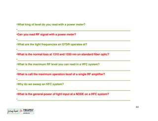
Broadband System - L
                           Satellites are spaced every
                            2nd degrees above earth


"C" Band
Toward satellite 6.0 GHz                                 "L" Band
Toward earth 4.0 GHz                                     Toward satellite 14.0 GHz
                                                         Toward earth 12.0 GHz


                TV
            TRANSMITTER
                           Headend

                                       Cable area

                                                                                     1
               Alignment and System Maintenance.
Broadband System Maintenance.


Since a HFC is bi-directional communications system, it needs to be aligned from
the Headend toward all the customers on the system and from each customer
toward the Headend.
The forward direction of the system usually operates from: 50 to 750 or 870 MHz
and the return path is usually from: 5 to 40 MHz.
The forward system consist of two transports medias, the first one been fiber
optic, followed by coaxial cable. The fiber section of the system needs to be
adjusted first. Fiber optic can operate at either 1310 or 1550 nm.
The second section, bi-directional coaxial cable, the forward section operate from
50 to 750 or 870 MHz, while the return section operate from 5 to 40 MHz.
For the reverse part, the fiber optic section need to be adjusted First, followed by
the coaxial section, except this adjustment has to be done in the reverse flow,
from the optical node to the Headend and from the next RF amplifier toward the
node and soon, then from each customer to the next return amplifier.


                                                                                2
Broadband Headend Combining.


                          Combining Network


                                          3
Broadband Bi-directional HFC System.


                                  Optical                     RF Amp.
                                  NODE
Antenna
                    Fiber optic                                             Coaxial cable


                                                                                                            RF Amp.
  Optical
  center


                                                               50-870 MHz
                                                               50-

                                                                        5-40 MHz
                                            50-870 MHz
                                            50-


                                                                                            Coaxial cable
                                                 Cablemodem


                                                5-40 MHz


                                                                                                            4
Equipments Needed to Adjust the System.


                                          5
Description of a NTSC Television Signal.


                                           6
Description of a QAM Television Signal.


A QAM signal (Quadrature Amplitude Modulation) can be 8, 16, 54 or 256 QAM.
Every QAM signal is 6 MHz wide and can carry up to 16 Analog channels in a
digital QAM Constellation form. You can only read the exact amplitude of a
QAM signal, with a Power Meter calibrated to this signal. A QAM channel can be
next to a NTSC signal or following each other as in this case.


                                                                            7
Final Adjustment of the Headend.

For the final adjustment at a Headend, you need to adjust each of the
channel (NTSC, QAM and Other) at their proper level. This adjustment
should provide a flat output at the final combining network. This adjustment
requires a; FSM, or a Spectrum Analyzer.


                                                                               8
Final Adjustment of the Headend.


Required RF flat input for:
1310 nm optical transmitter is usually +15.0 dBmV
1550 nm optical transmitter is usually +20.0 dBmV


             Output of an optical transmitter:
             1310 nm TX output is from 4.0 to 14.0 dBm
             1550 nm TX output is from 5.0 to 7.0 dBm
              EDFA output is 13.0 or 16.0 dBm


                                                         9
Final Adjustment of the Headend.
                                                +15.0 to +20.0 dBmV


                              At 1310 nm an optical signal can be
                              from +4.0 to +14.0 dBm. The output
Signal required at the
                              level can checked by a Power meter
input of an optical
                              or status monitoring.
transmitter.      This
signal can be verified
by a FSM, or a
Spectrum Analyzer.


                                                             10
Final Adjustment of the Headend.


All of the first RF amplifiers and all the Optical transmitter located at the
                       headend require a flat input.

                                                              10.0 dBmV
                                                                  To
                                                              +20.0 dBmV


                                                                           11
Final Adjustment of the Headend.


All RF amplifiers in the system require a sloped output. This slope is usually 10.0 dB
                for 750 MHz system and 12.5 dB for 870 MHz system.


                                 Amplifier Output;


                                                                                12
Final Adjustment of the Headend.


There are usually two things to verify at the input of each RF amplifier
    and each optical transmitter;
1.   Verify for the right input level, this is better done by a Spectrum analyzer,
     even if this can be accomplish using F.S.M. (Field Strength Meter)
2.   Verify the input flatness of the broadband system ( 50 to 750 / 870 MHz), this
     can be done with a Spectrum Analyzer a Sweep system or a FSM.
RF amplifier output;
1.   Verify the operating level, this is usually done at four sections of the
     spectrum, Low end (55 to 70 MHz), Mid Band (121 to 160 MHz, High Band (270
     to 330 MHz) Super High Band (450 to 555 MHz) and finally at the last RF signal
     550, 750 or 870 MHz .
2.   Verify the flatness of the spectrum of all amplifiers, this can be done with a
     Spectrum Analyzer a Sweep System or a FSM.
Optical Transmitter output;
1.   Verify the light level, this is done with a Power Meter, you require a Power
     Meter capable of reading between + 4.0 to + 14 dBm or a DC Volt Meter.
                                                                              13
Final Adjustment of the Headend.


        Response of a well aligned head, using a sweep system.


Using a sweep generator, located at the headend.   Using the actual signal of the HFC system.


                                                                                                14
Final Adjustment of the Headend.


Response of a well aligned head, using a spectrum analyzer.


                                                              15
Final Adjustment of the Headend.


View of an other type of Spectrum Analyzer.


  Where QAM and analog signal lives together


                                               16
Final Adjustment of the Headend.


Some test equipment are able to give you a general view of the system
 by the selection of some of the channels in the operating spectrum.


                                                                  17
Final Adjustment of the Headend.


Another type of Sweep System. This technology is called Sweepless Sweep,
     where it take an average of all the signal carried by the system.


                                                                   18
Final Adjustment of the Headend.


                    •You need to verify the output level
                    of each 1310 and 1550 nm optical
                    transmitter.
                    •With a system operating at 1550
                    nm, you’ll also need to verify the
                    output level of all EDFA


                                                    19
Final Adjustment in the Field.


             Adjusting an Optical Node in the field.


                                     Coaxial output


                                       Forward and return coaxial
                                       section.


                                       Single or dual forward optical
                                       receiver


                                      Single or dual return optical
                                      transmitter

Optical fibre.


                                                                      20
Final Adjustment in the Field.


                1.   In general a 0.0 dBm level is
                     required for a good optical
                     input. This can be verified by a
                     Power Meter or by a DC Volt
                     Meter.
                2.   The flatness of the system
                     should also be verified at these
                     locations.


                     Power Meter       DC Volt Meter


                                                   21
Final Adjustment in the Field.


             With a power meter, you need to disconnect
             the fiber optic at the input of the optical
             receiver and read the level of light. You also
             need to know the operation frequency, 1310
             or 1550 nm.
               Normal input level for a 750 MHz system,
               is between –1.0 to + 2.0 dBm


                         Power Meter
                                                    22
Final Adjustment in the Field.


            Most modern optical receiver have a DC
            test point, where you can read the
            actual light level.

             That light level will be different,
             depending on the equipment you
             system is using.

             This function will work for either the
             forward    receiver  or   the   return
             transmitter level.


                         DC Volt Meter
                                                   23
Final Adjustment in the Field.


Below are the RF level given by the optical receiver, with
                 the dBm or mW level.


                                                             24
Final Adjustment in the Field.

Each NODE requires an acceptance test, which are the
   following;
1.   System flatness
2.   Carrier to Noise
3.   CTB and CSO


      System response
         (flatness)


                                                       25
RF Amplifiers.


High gain with       Mini-Bridger       Line Extender
  4 outputs         with 2 outputs         amplifier
   amplifier           amplifier

     Type of RF amplifiers used in today HFC system


                                                        26
Coaxial Cable Behaviour with Temperature Changes.

  Reaction of the coaxial cable on a 870 MHz system, due to temperature change.


                                                                       Normal
                                                                       operatin
                                                                       g level.


As seen by the picture above, it is very important to have good automatic gain
control system on your amplifiers. This system could be a AGC/ASC, BODE or TLC
control system. It is also very important to have this system properly adjusted to
assure good performance.
                                                                                  27
RF Amplifiers.


                 28
RF Amplifiers.


                 29
RF Amplifiers.


                 30
RF Amplifiers.

The first thing to do at the input of an RF amplifier, is to verify the proper
operating input level, a fixed input attenuator can be install when the operating
level is to high, followed by the selection of the right cable equalizer, that way the
amplifier will get the right signal level and flatness at the first amplification circuit.


                                                                                     31
RF Amplifiers.
Selection of the proper Equalizer:
Not only it is important to select the right value equalizer at the input of each
amplifier, but it is also very important to select the right operating bandwidth
of the system. Selecting a 550 MHz equalizer in a 750 MHz system could
cause very bad response between 550 and 750 MHz.


                                                                               32
RF Amplifiers.


After verification of the right amplifier input level, you need to adjust the
amplifier to his right operation level. This is done by adjusting the GAIN and
the TILT control of the amplifier. Some amplifier only have a gain control, while
the slope is controlled by a BODE control. In all amplifiers you also need to
verify the operating SLOPE. That slope is usually 10.0 dB for a system
operating at 750 MHz and a 870 MHz system requires a 12.5 dB slope.


                                                                              33
Final Adjustment in the Field.


Below are the DC level reading at the test point of the optical
 receiver. A 2.0 VDC equal 1.0 mW or 0.0 dBm optical input.


                                                                  34
RF Amplifiers.
Because of the high gain of these two amplifier, it is often necessary to add the
right value JXP attenuator at the mid stage and the final stage of amplification to
these amplifiers.
•These amplifiers have 39 dB of gain at 750 MHz and let say you only want to
utilise 29 dB of these 39 dB. The first thing to do is add 4 dB to the 29 dB gain for a
total of 33 dB of gain.
•You then now need to subtract 39 to 33, which will give you a 6 dB difference.
That 6 dB should be divided in two, for a result of 3 dB, where a 3 dB JXP pad will
be introduce in the mid stage and another 3 dB will have to be introduce before
each output IC.


                                                                                  35
RF Amplifiers.

•After adjusting the amplifier to his right operating level, it is a good thing to
verify the overall response of this amplifier. This is done by adjusting some
variable controls, usually installed in the mid stage of amplification. This
operating should only be done using a sweep system not a F.S.M.
•Once in the spring and once in the fall, is also a good time to verify the
operating condition of all the NODE and the amplifiers in the system.


                                                                               36
RF Amplifiers.

Why do we need to verify the response of each RF amplifier?
•The reason we need to verify each amplifier, is to make sure each section of the
spectrum meets the necessary specifications, like C/N, CSO, CTB.
•To meet these technical specifications a broadband system need to meet a PEAK and
VALLEY response.
•Formula for PEAK and VALLEY requirements:
•N/10 +1
•Where N = the number of amplifiers in the Cascade.
•A 6 amplifiers Cascade would require : 6 / 10 +1 = 1.6   dB Peak / Valley


                                                                             37
RF Amplifiers.


Below are graphs showing and RF amplifier before and after response adjustment.


       Response of an amplifier            Response of the same amplifier
       before final adjustment of           after final adjustment of these
       these variables controls.                   variables controls.


                                                                              38
Final Testing of a Broadband System.


Once you have finalized the adjustment of the system, you need to make the
following test at each extremity of the system. These test are;
•Carrier to Noise.


This Carrier to Noise test need to
be done for a bandwidth of: 4.2
MHz. If the C/N is done with a
different bandwidth, it need to be
converted to a 4.2 MHz. The
conversion formula is:

              Bandwidthref
     10log
             Bandwidthnew

In a modern system the worst C/N       Above is a 49.1 dB Carrier to Noise Report. The
specification should be better than:    report is done using the Picture Carrier Level
48.0 dB                                 and the Noise reference outside of the 6 MHz
                                                            wide.
                                                                                         39
Final Testing of a Broadband System.

Once you have finalized the adjustment of the system, you need to
make the following test at each extremity of the system. These test are;
•Composite 2nd Order
•Composite 3th Order.

To do these two tests, CTB
and CSO, you generally
require   to  removed the
modulation on the channel
the test is done on. This
measurement can only be
done by a Spectrum Analyzer.
In a modern system the CTB
and CSO specification should
be better than 51.0 dB at
each extremity test.

                                 Above is a CSO of 70.4 dB, CTB of –70.9 dB and
                                                a C/N of 49.3 dB
                                                                                  40
Final Testing of a Broadband System.

 Once you have finalized the adjustment of the system, you need to make the
 following test at each extremity of the system. These test are;
 •Hum.
•HUM is 60 cycles coming from the AC line
that is introduced in the horizontal sweep
of the TV set, which occur at 59.95 Hz.
•The HUM is calculated in % or in dB.

•A good operating system should have 34
dB or 2% of HUM modulation or better.
•HUM can comes from a defective AC/DC
power supply of an amplifier, to amperage
draw thru a passive equipment or water in
connectors.
                                             Above shows a HUM report of 0.6% or 39
•To measure HUM you required a battery dB, well above the required specification
operated Scope, FSM with this option or a for well maintained Broadband System.
Spectrum Analyzer.

                                                                                 41
Final Testing of a Broadband System.

A Broadband system requires AC voltage from 40 to 90 Volts AC to operates
properly. To-day Broadband system generally operates with a UPS (Uninterrupted
Powering System) powering system. This system need to be verify twice a year to
make sure the batteries and the system are in good operating order.


         If AC is provided to each home, this should be
         checked at the time of the installation of equipment
         at the customer. These equipments could be IP
         telephony, Home security system, Digital Television
         system or Pay per View equipment.


                                                                          42
Test!


        43
•What king of level do you read with a power meter?
•_________________________________________________________________________
 _________________________________________________________________________
•Can you read RF signal with a power meter?
•_________________________________________________________________________
 _________________________________________________________________________
•What are the light frequencies an OTDR operates at?
•_________________________________________________________________________
 _________________________________________________________________________
•What is the normal loss at 1310 and 1550 nm on standard fiber optic?
                                                               optic?
•_________________________________________________________________________
 _________________________________________________________________________
•What is the maximum RF level you can read in a HFC system?
•_________________________________________________________________________
 _________________________________________________________________________
•What is call the maximum operation level of a single RF amplifier?
                                                         amplifier?
•_________________________________________________________________________
 _________________________________________________________________________
•Why do we sweep an HFC system?
•_________________________________________________________________________
 _________________________________________________________________________
•What is the general power of light input at a NODE on a HFC system?
                                                             system?
•_________________________________________________________________________
 _________________________________________________________________________

                                                                             44
45

Hfc l alignment and system maintenance

  • 1.
    Broadband System -L Satellites are spaced every 2nd degrees above earth "C" Band Toward satellite 6.0 GHz "L" Band Toward earth 4.0 GHz Toward satellite 14.0 GHz Toward earth 12.0 GHz TV TRANSMITTER Headend Cable area 1 Alignment and System Maintenance.
  • 2.
    Broadband System Maintenance. Sincea HFC is bi-directional communications system, it needs to be aligned from the Headend toward all the customers on the system and from each customer toward the Headend. The forward direction of the system usually operates from: 50 to 750 or 870 MHz and the return path is usually from: 5 to 40 MHz. The forward system consist of two transports medias, the first one been fiber optic, followed by coaxial cable. The fiber section of the system needs to be adjusted first. Fiber optic can operate at either 1310 or 1550 nm. The second section, bi-directional coaxial cable, the forward section operate from 50 to 750 or 870 MHz, while the return section operate from 5 to 40 MHz. For the reverse part, the fiber optic section need to be adjusted First, followed by the coaxial section, except this adjustment has to be done in the reverse flow, from the optical node to the Headend and from the next RF amplifier toward the node and soon, then from each customer to the next return amplifier. 2
  • 3.
    Broadband Headend Combining. Combining Network 3
  • 4.
    Broadband Bi-directional HFCSystem. Optical RF Amp. NODE Antenna Fiber optic Coaxial cable RF Amp. Optical center 50-870 MHz 50- 5-40 MHz 50-870 MHz 50- Coaxial cable Cablemodem 5-40 MHz 4
  • 5.
    Equipments Needed toAdjust the System. 5
  • 6.
    Description of aNTSC Television Signal. 6
  • 7.
    Description of aQAM Television Signal. A QAM signal (Quadrature Amplitude Modulation) can be 8, 16, 54 or 256 QAM. Every QAM signal is 6 MHz wide and can carry up to 16 Analog channels in a digital QAM Constellation form. You can only read the exact amplitude of a QAM signal, with a Power Meter calibrated to this signal. A QAM channel can be next to a NTSC signal or following each other as in this case. 7
  • 8.
    Final Adjustment ofthe Headend. For the final adjustment at a Headend, you need to adjust each of the channel (NTSC, QAM and Other) at their proper level. This adjustment should provide a flat output at the final combining network. This adjustment requires a; FSM, or a Spectrum Analyzer. 8
  • 9.
    Final Adjustment ofthe Headend. Required RF flat input for: 1310 nm optical transmitter is usually +15.0 dBmV 1550 nm optical transmitter is usually +20.0 dBmV Output of an optical transmitter: 1310 nm TX output is from 4.0 to 14.0 dBm 1550 nm TX output is from 5.0 to 7.0 dBm EDFA output is 13.0 or 16.0 dBm 9
  • 10.
    Final Adjustment ofthe Headend. +15.0 to +20.0 dBmV At 1310 nm an optical signal can be from +4.0 to +14.0 dBm. The output Signal required at the level can checked by a Power meter input of an optical or status monitoring. transmitter. This signal can be verified by a FSM, or a Spectrum Analyzer. 10
  • 11.
    Final Adjustment ofthe Headend. All of the first RF amplifiers and all the Optical transmitter located at the headend require a flat input. 10.0 dBmV To +20.0 dBmV 11
  • 12.
    Final Adjustment ofthe Headend. All RF amplifiers in the system require a sloped output. This slope is usually 10.0 dB for 750 MHz system and 12.5 dB for 870 MHz system. Amplifier Output; 12
  • 13.
    Final Adjustment ofthe Headend. There are usually two things to verify at the input of each RF amplifier and each optical transmitter; 1. Verify for the right input level, this is better done by a Spectrum analyzer, even if this can be accomplish using F.S.M. (Field Strength Meter) 2. Verify the input flatness of the broadband system ( 50 to 750 / 870 MHz), this can be done with a Spectrum Analyzer a Sweep system or a FSM. RF amplifier output; 1. Verify the operating level, this is usually done at four sections of the spectrum, Low end (55 to 70 MHz), Mid Band (121 to 160 MHz, High Band (270 to 330 MHz) Super High Band (450 to 555 MHz) and finally at the last RF signal 550, 750 or 870 MHz . 2. Verify the flatness of the spectrum of all amplifiers, this can be done with a Spectrum Analyzer a Sweep System or a FSM. Optical Transmitter output; 1. Verify the light level, this is done with a Power Meter, you require a Power Meter capable of reading between + 4.0 to + 14 dBm or a DC Volt Meter. 13
  • 14.
    Final Adjustment ofthe Headend. Response of a well aligned head, using a sweep system. Using a sweep generator, located at the headend. Using the actual signal of the HFC system. 14
  • 15.
    Final Adjustment ofthe Headend. Response of a well aligned head, using a spectrum analyzer. 15
  • 16.
    Final Adjustment ofthe Headend. View of an other type of Spectrum Analyzer. Where QAM and analog signal lives together 16
  • 17.
    Final Adjustment ofthe Headend. Some test equipment are able to give you a general view of the system by the selection of some of the channels in the operating spectrum. 17
  • 18.
    Final Adjustment ofthe Headend. Another type of Sweep System. This technology is called Sweepless Sweep, where it take an average of all the signal carried by the system. 18
  • 19.
    Final Adjustment ofthe Headend. •You need to verify the output level of each 1310 and 1550 nm optical transmitter. •With a system operating at 1550 nm, you’ll also need to verify the output level of all EDFA 19
  • 20.
    Final Adjustment inthe Field. Adjusting an Optical Node in the field. Coaxial output Forward and return coaxial section. Single or dual forward optical receiver Single or dual return optical transmitter Optical fibre. 20
  • 21.
    Final Adjustment inthe Field. 1. In general a 0.0 dBm level is required for a good optical input. This can be verified by a Power Meter or by a DC Volt Meter. 2. The flatness of the system should also be verified at these locations. Power Meter DC Volt Meter 21
  • 22.
    Final Adjustment inthe Field. With a power meter, you need to disconnect the fiber optic at the input of the optical receiver and read the level of light. You also need to know the operation frequency, 1310 or 1550 nm. Normal input level for a 750 MHz system, is between –1.0 to + 2.0 dBm Power Meter 22
  • 23.
    Final Adjustment inthe Field. Most modern optical receiver have a DC test point, where you can read the actual light level. That light level will be different, depending on the equipment you system is using. This function will work for either the forward receiver or the return transmitter level. DC Volt Meter 23
  • 24.
    Final Adjustment inthe Field. Below are the RF level given by the optical receiver, with the dBm or mW level. 24
  • 25.
    Final Adjustment inthe Field. Each NODE requires an acceptance test, which are the following; 1. System flatness 2. Carrier to Noise 3. CTB and CSO System response (flatness) 25
  • 26.
    RF Amplifiers. High gainwith Mini-Bridger Line Extender 4 outputs with 2 outputs amplifier amplifier amplifier Type of RF amplifiers used in today HFC system 26
  • 27.
    Coaxial Cable Behaviourwith Temperature Changes. Reaction of the coaxial cable on a 870 MHz system, due to temperature change. Normal operatin g level. As seen by the picture above, it is very important to have good automatic gain control system on your amplifiers. This system could be a AGC/ASC, BODE or TLC control system. It is also very important to have this system properly adjusted to assure good performance. 27
  • 28.
  • 29.
  • 30.
  • 31.
    RF Amplifiers. The firstthing to do at the input of an RF amplifier, is to verify the proper operating input level, a fixed input attenuator can be install when the operating level is to high, followed by the selection of the right cable equalizer, that way the amplifier will get the right signal level and flatness at the first amplification circuit. 31
  • 32.
    RF Amplifiers. Selection ofthe proper Equalizer: Not only it is important to select the right value equalizer at the input of each amplifier, but it is also very important to select the right operating bandwidth of the system. Selecting a 550 MHz equalizer in a 750 MHz system could cause very bad response between 550 and 750 MHz. 32
  • 33.
    RF Amplifiers. After verificationof the right amplifier input level, you need to adjust the amplifier to his right operation level. This is done by adjusting the GAIN and the TILT control of the amplifier. Some amplifier only have a gain control, while the slope is controlled by a BODE control. In all amplifiers you also need to verify the operating SLOPE. That slope is usually 10.0 dB for a system operating at 750 MHz and a 870 MHz system requires a 12.5 dB slope. 33
  • 34.
    Final Adjustment inthe Field. Below are the DC level reading at the test point of the optical receiver. A 2.0 VDC equal 1.0 mW or 0.0 dBm optical input. 34
  • 35.
    RF Amplifiers. Because ofthe high gain of these two amplifier, it is often necessary to add the right value JXP attenuator at the mid stage and the final stage of amplification to these amplifiers. •These amplifiers have 39 dB of gain at 750 MHz and let say you only want to utilise 29 dB of these 39 dB. The first thing to do is add 4 dB to the 29 dB gain for a total of 33 dB of gain. •You then now need to subtract 39 to 33, which will give you a 6 dB difference. That 6 dB should be divided in two, for a result of 3 dB, where a 3 dB JXP pad will be introduce in the mid stage and another 3 dB will have to be introduce before each output IC. 35
  • 36.
    RF Amplifiers. •After adjustingthe amplifier to his right operating level, it is a good thing to verify the overall response of this amplifier. This is done by adjusting some variable controls, usually installed in the mid stage of amplification. This operating should only be done using a sweep system not a F.S.M. •Once in the spring and once in the fall, is also a good time to verify the operating condition of all the NODE and the amplifiers in the system. 36
  • 37.
    RF Amplifiers. Why dowe need to verify the response of each RF amplifier? •The reason we need to verify each amplifier, is to make sure each section of the spectrum meets the necessary specifications, like C/N, CSO, CTB. •To meet these technical specifications a broadband system need to meet a PEAK and VALLEY response. •Formula for PEAK and VALLEY requirements: •N/10 +1 •Where N = the number of amplifiers in the Cascade. •A 6 amplifiers Cascade would require : 6 / 10 +1 = 1.6 dB Peak / Valley 37
  • 38.
    RF Amplifiers. Below aregraphs showing and RF amplifier before and after response adjustment. Response of an amplifier Response of the same amplifier before final adjustment of after final adjustment of these these variables controls. variables controls. 38
  • 39.
    Final Testing ofa Broadband System. Once you have finalized the adjustment of the system, you need to make the following test at each extremity of the system. These test are; •Carrier to Noise. This Carrier to Noise test need to be done for a bandwidth of: 4.2 MHz. If the C/N is done with a different bandwidth, it need to be converted to a 4.2 MHz. The conversion formula is: Bandwidthref 10log Bandwidthnew In a modern system the worst C/N Above is a 49.1 dB Carrier to Noise Report. The specification should be better than: report is done using the Picture Carrier Level 48.0 dB and the Noise reference outside of the 6 MHz wide. 39
  • 40.
    Final Testing ofa Broadband System. Once you have finalized the adjustment of the system, you need to make the following test at each extremity of the system. These test are; •Composite 2nd Order •Composite 3th Order. To do these two tests, CTB and CSO, you generally require to removed the modulation on the channel the test is done on. This measurement can only be done by a Spectrum Analyzer. In a modern system the CTB and CSO specification should be better than 51.0 dB at each extremity test. Above is a CSO of 70.4 dB, CTB of –70.9 dB and a C/N of 49.3 dB 40
  • 41.
    Final Testing ofa Broadband System. Once you have finalized the adjustment of the system, you need to make the following test at each extremity of the system. These test are; •Hum. •HUM is 60 cycles coming from the AC line that is introduced in the horizontal sweep of the TV set, which occur at 59.95 Hz. •The HUM is calculated in % or in dB. •A good operating system should have 34 dB or 2% of HUM modulation or better. •HUM can comes from a defective AC/DC power supply of an amplifier, to amperage draw thru a passive equipment or water in connectors. Above shows a HUM report of 0.6% or 39 •To measure HUM you required a battery dB, well above the required specification operated Scope, FSM with this option or a for well maintained Broadband System. Spectrum Analyzer. 41
  • 42.
    Final Testing ofa Broadband System. A Broadband system requires AC voltage from 40 to 90 Volts AC to operates properly. To-day Broadband system generally operates with a UPS (Uninterrupted Powering System) powering system. This system need to be verify twice a year to make sure the batteries and the system are in good operating order. If AC is provided to each home, this should be checked at the time of the installation of equipment at the customer. These equipments could be IP telephony, Home security system, Digital Television system or Pay per View equipment. 42
  • 43.
  • 44.
    •What king oflevel do you read with a power meter? •_________________________________________________________________________ _________________________________________________________________________ •Can you read RF signal with a power meter? •_________________________________________________________________________ _________________________________________________________________________ •What are the light frequencies an OTDR operates at? •_________________________________________________________________________ _________________________________________________________________________ •What is the normal loss at 1310 and 1550 nm on standard fiber optic? optic? •_________________________________________________________________________ _________________________________________________________________________ •What is the maximum RF level you can read in a HFC system? •_________________________________________________________________________ _________________________________________________________________________ •What is call the maximum operation level of a single RF amplifier? amplifier? •_________________________________________________________________________ _________________________________________________________________________ •Why do we sweep an HFC system? •_________________________________________________________________________ _________________________________________________________________________ •What is the general power of light input at a NODE on a HFC system? system? •_________________________________________________________________________ _________________________________________________________________________ 44
  • 45.