Dev Dives: Streamline document processing with UiPath Studio Web
Lect catv
1. Introduction to CATV Page 1 of 7
An Introduction to Basic CATV
Historic Perspective
From An Overview of Cable Television in the United States: by Dr. Walter Ciciora
"Prior to the 1990s, cable television systems were not intended to be general-purpose communications mechanisms.
Their primary and often sole purpose was the transportation of a variety of entertainment television signals
tosubscribers. Thus, they needed to be one-way transmission paths from a central location, called a headend, to each
subscriber’s home, delivering essentially the same signals to each subscriber. The signals are intended for use with the
consumer-electronics equipment that subscribers already own. This equipment is built to operate on the current U.S.
television technical standard called NTSC after the organization that created it in 1941, the National Television Systems
Committee. This black-and-white television standard was modified in 1953 to provide compatible color information to
color television receivers, and again in 1984 to add compatible stereo sound.
"The original purpose for cable television was to deliver broadcast signals in areas where they were not received in an
acceptable manner with an antenna. These systems were called community antenna television, or CATV. In 1948, Ed
Parson of Astoria, Oregon, built the first CATV system consisting of twin-lead transmission wire strung from housetop to
housetop. In 1950, Bob Tarlton built a system in Lansford, Pennsylvania, using coaxial cable on utility poles under a
franchise from the city."
"In most CATV systems, off-air signals were not available or were very weak because of the terrain or the distance of the
receiver from television transmitters. In some areas, such as New York City, multiple signal reflections and shadows
cast by buildings made reception difficult. In both of these environments, a hard-wire method of delivery of signals to
subscribers was welcomed. The first operators of these systems were retail TV receiver dealers who sought to expand
the market for the sale of their products by also providing the signals that the products required. By the late 1960s,
nearly all of the areas of the U.S. that could benefit from a community antenna had been served. Growth in the cable
industry all but stopped.
"In the mid 1970s, an embryonic technology breathed new life into cable television. This technology was satellite
delivery of signals to cable systems, which added more channels than were available from terrestrial broadcasters.
While satellites and earth stations were very expensive investments, these programming pioneers understood that the
costs could be spread over many cable operators who, in turn, serve many subscribers."
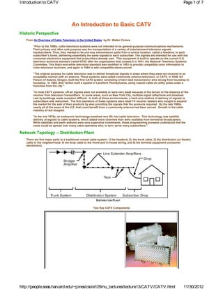
Network Topology -- Distribution Plant
There are five major parts to a traditional coaxial cable system: 1) the headend, 2), the trunk cable, 3) the distribution (or feeder)
cable in the neighborhood, 4) the drop cable to the home and in-house wiring, and 5) the terminal equipment (consumer
electronics).
Two Key CATV Components
http://people.seas.harvard.edu/~jones/cscie129/nu_lectures/lecture13/CATV/CATV.html 11/30/2012
2. Introduction to CATV Page 2 of 7
Hermetic Inline Amplifiers
Hermetic Outdoor Taps
CATV System Topologies
Channel Carriage Capacity
TV Broadcast Frequency Plan:
http://people.seas.harvard.edu/~jones/cscie129/nu_lectures/lecture13/CATV/CATV.html 11/30/2012
3. Introduction to CATV Page 3 of 7
CATV Systems:
Power Considerations
Signals in cable systems are measured in dB relative to 1 mV(millivolt) across 75 ohms. This measure is called dBmV.
Expressed in dBmV, the minimum room-temperature noise in a perfect cable system is -59.17 dBmV.
Starting at the home, the objective is to deliver at least 0 dBmV, but no more than 10 dBmV to the terminal on the
television receiver. Lower numbers produce snowy pictures and higher numbers overload the television receiver’s tuner,
resulting in cross modulation of the channels. If a converter or a descrambler is used, its noise figure must be taken into
account. There are two reasons for staying toward the low side of the signal range: cost and the minimization of
interference in the event of a signal leak caused by a faulty connector, damaged piece of cable, or defects or inadequate
shielding in the television receiver. Low signal levels may cause poor pictures for the subscriber who insists on
unauthorized splitting in the home to serve multiple receivers. Working our way back up the plant, we need a signal level
of 10 to 15 dBmV at the tap to compensate for losses in the drop cable. The design objectives of the distribution part of
the cable system involve an adequate level of power not only to support the attenuation characteristics of the cable, but
to allow energy to be diverted to subscribers’ premises. Energy diverted to the subscriber is lost from the distribution
cable. This loss is called flat loss because it is independent of frequency. Loss in the cable itself is a square-root
function of frequency (Cable Properties) and is therefore contrasted to flat loss. Because of flat losses, relatively high
power levels are required in the distribution part of the plant, typically 48 dBmV at the input to the distribution plant.
These levels force the amplifiers in the distribution part of the plant to reach into regions of their transfer characteristics
that are slightly non-linear. As a result, only one or two amplifiers, called line extenders, can be cascaded in the
distribution part of the plant. These amplifiers are spaced 300 to 900 feet apart depending on the number of taps required
by the density of homes. Because the distribution part of the plant is operated at higher power levels, non-linear effects
become important. The television signal has three principal carriers, the video carrier, the audio carrier, and the color
subcarrier. These concentrations of energy in the frequency domain give rise to a wide range of “beats” when passed
through non-linearities. To minimize these effects, the audio carrier is attenuated about 15 dB below the video carrier.
In the days when cable systems only carried the 12 VHF channels, second-order distortions created spectrum products
that fell out of the frequency band of interest. As channels were added to fill the spectrum from 54 MHz to as much as
750 MHz (1 GHz in a couple of systems), second-order effects were minimized through the use of balanced, push-pull
output circuits in amplifiers. The third-order component of the transfer characteristic dominates in many of these
designs. Figure 1.8 demonstrates the triple-beat phenomena. The total effect of all thecarriers beating against each other
gives rise to an interference called composite triple beat (CTB). CTB is measured with a standard procedure involving 35-
channel carriers. In a 35-channel cable system, about 10,000 beat products are created. Channel 11 suffers the most with
350 of these products falling in its video passband. Third-order distortions increase nearly 6 dB for each doubling of the
number of amplifiers in cascade. A 1-dB reduction in amplifier output level will generally reduce CTB by 2 dB.
http://people.seas.harvard.edu/~jones/cscie129/nu_lectures/lecture13/CATV/CATV.html 11/30/2012
4. Introduction to CATV Page 4 of 7
The Advent of FO CATV Trunks:
Again from An Overview of Cable Television in the United States: by Dr. Walter Ciciora
"The late 1980s and early 1990s brought a high level of interest in and excitement about the 'Information Superhighway,'
also called the National Information Infrastructure (NII). A variety of drivers are energetically pushing the NII. Early
efforts came from the telephone industry seeking to justify upgrading heavily depreciated
plant. Since the twisted-pair plant did a fine job of delivering plain old telephone service (POTS), another reason for
replacing it was needed. That reason needed to be a bandwidth hog. Digitized voice did not fill the bill.
It could be handled over the existing twisted-copperpairs. Only computer data and digitized video held the promise of
providing a justification for declaring twisted-copper pair obsolete. So the telephone systems began a quest for
permission to add fiber and digital technology to the rate base. Congressmen caught the bug and decided that a vast
government-sponsored program was needed to build the Information Superhigh-way. The NII was born.
"……The last few years have brought exciting trends employing new technologies. Fiber is now being installed to
upgrade older systems and as part of rebuilds and new builds. The old trunk system of long cascades of amplifiers is
now considered obsolete. Work on new amplifier technologies will allow a realization of cable’s inherent bandwidth,
which exceeds 1 GHz. A bandwidth of 1 GHz contains 160 slots of 6 MHz. These can be allocated to NTSC, HDTV
simulcast, and to new services. The most exciting potential lies with utilizing video-compres-sion technology to squeeze
four or more NTSC-like quality signals in a 6-MHz slot."
http://people.seas.harvard.edu/~jones/cscie129/nu_lectures/lecture13/CATV/CATV.html 11/30/2012
5. Introduction to CATV Page 5 of 7
(source)
http://people.seas.harvard.edu/~jones/cscie129/nu_lectures/lecture13/CATV/CATV.html 11/30/2012
6. Introduction to CATV Page 6 of 7
http://people.seas.harvard.edu/~jones/cscie129/nu_lectures/lecture13/CATV/CATV.html 11/30/2012
7. Introduction to CATV Page 7 of 7
References:
Connecting Homes to the Internet: An Engineering Cost Model of Cable vs. ISDN by Sharon Eisner Gillet
An Overview of Cable Television in the United States: by Dr. Walter Ciciora. Updated 1995
The Cable Connection: The Role of Cable Television in the National Information Infrastructure
The Cable Modem Info Center:
Cable Modem Primer
Cable Modem Tutorial
Thi s page was pr epar ed and i s m nt ai ned by R. Vi ct or Jones
ai
Com ent s t o: jones@deas.harvard.edu.
m
Last updat ed M ay 10, 2004
http://people.seas.harvard.edu/~jones/cscie129/nu_lectures/lecture13/CATV/CATV.html 11/30/2012