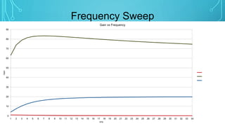
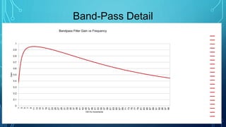
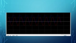
PULSE OXIMETER
EVANDER LEMOS
ORCIDIO SANTOS
EE3113
PROFESSOR AUGUST ALLO
WHAT IS PULSE OXIMETER?
• Measure the Pulse rate
• Monitoring oxygenation
• Fitness monitoring
• Several Medical applications
Circuit Overview
Simplification:
Neutral Reference
Stage Breakdown
Principles of Operation
 LC Oscillator generates 5kHz signal
 Filters trim frequencies above and below desired signal
 High-pass filters double as amplifier stages to boost gain
 Constant Amplifier boosts gain significantly
 Comparator generates a square wave when signal
exceeds reference value
Frequency Sweep
0
10
20
30
40
50
60
70
80
90
1 2 3 4 5 6 7 8 9 10 11 12 13 14 15 16 17 18 19 20 21 22 23 24 25 26 27 28 29 30 31 32 33 34
Gain
kHz
Gain vs Frequency
Filter A (band pass)
Net Gain (dB)
Filter B (high pass)
Band-Pass Detail
0
0.1
0.2
0.3
0.4
0.5
0.6
0.7
0.8
0.9
1
1
3
5
7
9
11
13
15
17
19
21
23
25
27
29
31
33
35
37
39
41
43
45
47
49
51
53
55
57
59
61
63
65
67
69
71
73
75
77
79
81
83
85
87
89
91
93
95
97
99
Gain
100 Hz Increments
Bandpass Filter Gain vs Frequency
1
2
3
4
5
6
7
8
9
10
11
12
13
14
15
16
17
18
19
20
21
Gain at 5kHz
Circuit Sensitivity
 Huge gain in target band
 Comparator Reference only 0.5V above Neutral
Reference
 Result: Comparator can trip with an input of just 36
microvolts above Neutral Reference
 Original Designer compensated with stronger filtering on
power supply
 Reducing the final gain stage or raising the Comparator
Reference would have also worked.
BLOCK DIAGRAM
INFRARED TX AND RX
PULSE SENSOR
SIGNAL CONDITIONING
STAGE
OUTPUT SIGNAL
COMPONENTS
• Photosensor APDS9008
• Op Amp MCP6001
• IR Diode
• Capacitors
• Resistors
PROPOSED CIRCUIT
EQUIVALENT CIRCUIT
CIRCUIT ANALYSIS
• Infrared TX and RX
• Photodiode operating in Photoconductivity mode
fbw= 1/(2*pi*Rload*Cj)
Max Reverse Voltage = …
CIRCUIT ANALYSIS
• Signal conditioning
Av = -Rf/Rin = (3.3x10^6)/(10x10^3) = 330 = 50 dB
CIRCUIT ANALYSIS
• Simulation
CHALLENGES
• Simulating the circuit
• Hardware implementation
• Limitation
Interesting Notes
 Voltage dividers cannot be separated from the amplifiers
 Circuit more sensitive to noise than anticipated
 Band-pass filter does not contribute gain
CONCLUSION
• The implementation of a heart monitor involves low cost amplifier and
filter components which can be find everywhere.
THANK YOU
Circuit Source
 Maxim Integrated
https://www.maximintegrated.com/en/app-
notes/index.mvp/id/3845

Heart beat "Pulse Oximeter