This document is a case study book on formally specifying and documenting systems using the Z notation. It contains 6 chapters that provide an introduction to formal specification using Z, discuss industrial use of formal methods, provide a brief introduction to the Z notation, and present case studies on specifying network services, UNIX software, instruction sets, graphics concepts, and window systems in Z. The case studies demonstrate how Z can be used to specify existing systems at varying levels of abstraction.


![documentation All material that serves primarily to describe a system and make it
more understandable, rather than to contribute in some way to the actual operation
of the system. . . .
formal specification 1. A specification written and approved in accordance with
established standards.
2. A specification written in a formal notation, such as VDM or Z.
Z A formal notation based on set algebra and predicate calculus for the specifica-
tion of computing systems. It was developed at the Programming Research Group,
Oxford University. Z specifications have a modular structure. . . .
Dictionary of Computing [221]
CICS and IBM are trademarks of International Business Machines Corporation.
DEC, VAX and MicroVAX are trademarks of Digital Equipment Corporation.
Inmos and Occam are trademarks of SGS-Thomson Microelectronics.
MC68000 is a trademark of Motorola Computer Systems.
P OST S CRIPT is a trademark of Adobe, Inc.
Sun is a trademark of Sun Microsystems, Inc.
UNIX is a registered trademark in the USA and other countries licensed through
X/Open Company Ltd.
X Window System is a trademark of X Consortium, Inc.](https://image.slidesharecdn.com/zbook-130114070646-phpapp01/75/Zbook-3-2048.jpg)


![4 Formal Specification and Documentation using Z
1.2 Formal Specification
A formal specification is simply a description of a system using a mathematical no-
tation. The advantage of using mathematics is that it is precise, unlike the more am-
biguous natural language and diagrams which are often used for specifications. The
disadvantage is the barrier of the notation. More people understand natural language
than mathematics. The specification language must first be learned, and then experi-
ence in its use needs to be gained before its full benefits can be attained.
A specification language may be used as a design tool and, if the notation is read-
able enough, as a documentation tool. The actual process of designing a system may
be undertaken using a formal notation to communicate ideas between members of a
design team. Once the design has been finished, it can then form the basis for a manual
describing the system.
Note that in the context of this book, the initial ‘design’ is considered to be the
interface specification of the system with the outside world and the ‘implementation’
is considered to be the refinement of this design into a working system.
1.2.1 The Z notation
Z has been developed at Oxford University since the late 1970’s by members of the
Programming Research Group (PRG) within the Computing Laboratory [203, 336,
376, 381]. It is a typed language based on set theory and first order predicate logic.
There is nothing very unusual about the mathematics employed, although a few oper-
ators have been added as experience has been gained in its use.
The problem with using mathematics alone is that large specifications very quickly
become unmanageable and unreadable. Hence as well as the basic mathematical no-
tation, Z includes a schema notation to aid the structuring of specifications. This
provides the framework for a textual combination of sections of mathematics (known
as schemas) using schema operators. Many of these match equivalent operators in the
mathematical notation.
As well as the formal text, a Z specification should contain English (or some other
natural language) to explain the mathematical description. Ideally, the informal de-
scription should remain readable even if the formal sections are removed from the
document. However, if there is a conflict between the two descriptions, the mathemat-
ics is the final arbiter since it provides a more precise specification.
The idea of an abstract Z specification is to describe what a system does rather than
how it does it. Imperative programming languages are specifications, but these con-
centrate on how the result is to be achieved. Functional programming languages are
more like specification languages since these describe what result is required. How-
ever they are designed to be executable. Z can be used in a functional style. However
it is possible (and sometimes desirable) to write non-deterministic specifications in
Z. This means the exact execution of the specification cannot be determined. The
Z notation is designed to be expressive and understandable (by humans) rather than
executable (by computers).
Some specification languages are designed to be executable (although very ineffi-
ciently) so that rapid prototyping of the system is possible. However in such specifi-
cations, the designers often have to think about making the specification executable in](https://image.slidesharecdn.com/zbook-130114070646-phpapp01/75/Zbook-17-2048.jpg)

![Chapter 1 Formal Specification using Z 7
Finally it is possible to refine an abstract design towards the concrete implemen-
tation by a series of state and operation refinement steps. For example, a set in an
abstract state may not be immediately, or efficiently, implementable in a particular
programming language. It could be implemented as an array, hash table, binary tree
or other convenient data structure. Each refinement step is related to the previous
one by a mathematical relation. There are a number of rules or proof obligations
governing valid refinement steps. This refinement process will also make any non-
determinism in the abstract specification deterministic in the final implementation by
making implementation-dependent design choices.
1.3 Case Studies
Besides the work on the theoretical underpinning of Z, many case studies using the no-
tation have also been undertaken to ensure its applicability in a practical environment.
This section gives an overview of the case studies presented later in the book.
1.3.1 Network services
The Distributed Computing Software (DCS) project at the Oxford University Com-
puting Laboratory designed a number of network services using the Z language. The
results have been documented in several monographs [55, 56, 172]. The designs have
formed the basis for manuals for each of the services. Two different types of man-
ual have been produced. User Manuals have been designed to describe each service
from the point of view of a client program using the service via Remote Procedure
Calls (RPCs) over a network. In addition, Implementor Manuals have been produced
for some services. These describe how the service may be implemented internally. Z
is still used for this description, although it is assumed that an imperative sequential
programming language will be used for the final implementation. As well as the User
and Implementor Manuals, a Common Service Framework manual has been produced.
This describes common parts of services to avoid repetition in individual manuals.
Significant effort was expended in the presentation of the manuals to make them as
readable as possible while still employing a formal notation.
A User Manual
A user will normally be interested in how a service reacts with the outside world rather
than with the detailed inner workings of the service. Thus the manual can provide an
abstract view of the service. This may be based directly on the original abstract design.
Indeed, the initial design of the network services which have been produced during the
project have consisted of a skeleton version of the User Manual. This has subsequently
been tidied up and improved for the final version of the manual, thus greatly reducing
the amount of time spent producing documentation.
Each User Manual is split into a number of sections. After a general introduction,
the abstract state of the service is presented. Next common parameters shared by
a number of service operations are covered (for example, all operations produce an
output report). A section details the result of operations when an error occurs and the](https://image.slidesharecdn.com/zbook-130114070646-phpapp01/75/Zbook-20-2048.jpg)
![Chapter 1 Formal Specification using Z 9
group such aspects of the services in a separate document for use in the description of
each specific service.
The Common Service Framework covers such features. First an example of a gen-
eralized service is presented, including all common features which may be used by
a particular service. Then a number of common subsystems are formally described.
These include extra operations to deal with concerns like time, accounting, statistics
and access control. Any combination of these subsystems may be included in a given
service. This will increase the number of operations which may be performed on that
service.
Next, it is shown how all the services in the distributed system may be formally com-
bined to produce a specification of the complete system. Network attributes, including
authentication, and client attributes (e.g., identification) are also covered. Finally a
summary of the common sets and data types used by the services is given.
Part II provides some actual examples of network service manuals. Chapter 4
presents some more detailed motivation and a very simple service by way of example.
Chapter 5 takes the form of a more substantial user manual.
1.3.2 Other case studies
As well as designing and documenting network services, a number of case studies
of existing systems in real use have been undertaken. Parts of the systems under
investigation were specified in Z to gain a greater understanding of their operation.
UNIX software
The UNIX [37] file system was used as one of the earliest examples of the specification
of a real system, demonstrating the structuring feature know as the schema calculus
that is provided as part of Z to enable large specifications to be tackled [298]. Part III
of this book provides further examples of more detailed software that has been imple-
mented under UNIX. Chapter 6 presents a text formatting tool, useful for justifying
ASCII text in a file [44]. A matching UNIX manual page is provided for comparison by
the reader. Chapter 7 gives a specification for a library of C routines that implement
an event-based input system for UNIX workstations [80].
Instruction sets
Z is not necessarily restricted to the specification of software-based systems. Any sys-
tem which may be viewed as an abstract state on which a number of operations may
be performed can be conveniently specified in Z. For example, Z has proved partic-
ularly good for specifying instruction sets. The Motorola 6800 8-bit microprocessor
instruction set has been completely specified as an exercise [39, 38]. Additionally,
large parts of the Inmos (now SGS-Thomson) Transputer [224] and Motorola 68000
16/32-bit microprocessor instruction sets have also been specified in Z [45, 149, 350].
Z scales up to these larger instruction sets with few problems, mainly because of the
schema notation.
Part IV of the book gives an introduction to the formal specification of instruction
sets in Z. Chapter 8 presents some general concepts concerning operations on micro-](https://image.slidesharecdn.com/zbook-130114070646-phpapp01/75/Zbook-22-2048.jpg)
![10 Formal Specification and Documentation using Z
processor words, consisting of fixed length sequences of bits. Next, Chapter 9 gives a
portion of a real microprocessor instruction set, namely that of the Transputer.
Graphics and window systems
As a case study, a number of existing window systems have been studied [43, 47].
Originally it had been intended to compare parts of a number of distributed systems
using Z. However, the authors of potential systems for investigation could only supply
academic papers (not enough information) or the source code (too much information).
What was required was some form of informal documentation for the system. Because
window systems are used directly by users, there seems to be more readable docu-
mentation for such systems. Hence it was decided to attempt to produce a high-level
specification for three window systems. The specifications could be used to contrast
the systems and test the documentation for completeness.
The three systems chosen were X (a distributed window system from MIT, and
now widely used), WM (part of Andrew, a distributed system developed at Carnegie-
Mellon University) and the Blit, including mux (developed at Bell Laboratories, Mur-
ray Hill). In each case, omissions and ambiguities in the documentation were discov-
ered by attempting to formalize the system. Where necessary, intelligent guesses were
made about the actual operation. These were usually correct, but not always. Using
such specifications, it would be a simple matter to update existing documentation, or
even rewrite it from scratch.
Although Z has been developed as a design tool, it is also well suited for post hoc
specifications of existing systems, and for detecting errors and anomalies in the docu-
mentation of such systems.
Window systems make use of basic graphical concepts such as pixels (short for
‘picture elements’), and operations on these elements. Part V formalizes some of these
ideas in Z. Chapter 10 defines the basic graphical concepts and Chapter 11 uses these
to define ‘raster-op’ functions, useful for manipulating pixel maps. Part VI builds on
these to specify parts of three existing window systems mentioned above, namely WM
(Chapter 12), the Blit (Chapter 13), and X (Chapter 14).
1.4 Conclusions
Z is one of a number of specification languages which are being developed around
the world. It is a general purpose specification language. For example, Z could be
specified using itself [376, 79]. It could also be used to specify a more special pur-
pose language such as CSP [215], which is designed to handle concurrency. Z itself is
cumbersome for specifying parallel systems. Its use will produce a much longer spec-
ification than if CSP is used. Hence it is more convenient to use a language like CSP
in such cases. Work has been undertaken to attempt to combine some of the features
of CSP with Z [28, 239, 438].
Z has direct competitors. The most mature of these is probably VDM, advocated
by Jones [233]. This is also based on set theory and predicates, and is similar to Z in
a number of respects. Its differences include explicitly stating which components are
read and written by an operation, and explicitly separating the preconditions, involv-
ing only the before state, and postconditions, also involving the after state. A more](https://image.slidesharecdn.com/zbook-130114070646-phpapp01/75/Zbook-23-2048.jpg)
![Chapter 1 Formal Specification using Z 11
advanced toolset is available for VDM, although the situation is being rectified for
Z. The notation is arguably less readable that Z. It lacks an equivalent to the schema
notation of Z which is so useful for aiding the structuring and readability of specifi-
cations. Subsequently, a more comprehensive set of notations, with tool support, has
been produced in the form of RAISE [343].
Another approach to formal specification is that of algebraic specification (e.g.,
Larch [183] and OBJ [176]). These uses abstract data types in which the allowed
operators on types are specified rather than the types themselves. This approach is
theoretically very attractive but problems can occur in scaling up specifications for
industrially sized examples.
1.4.1 Z – advantages
Z may be used to produce readable specifications. It has been designed to be read by
humans rather than computers. Thus it can form the basis for documentation.
Large specifications are manageable in Z, using the schema notation for structur-
ing. It is possible to produce hierarchical specifications. A part of a system may be
specified in isolation, and then this may be put into a global context.
Z is liked by users. Many methods are foisted on designers in industry by managers
attempting to improve efficiency. From the feedback which has been obtained, it seems
that the use of Z is one of the few specification techniques which has not been received
with reluctance by industrial users.
The notation is gradually gaining acceptance in industry, at least in the United King-
dom and is taught in many computer science curricula [314]. A regular Z User Meet-
ing series (see page 229) has been established. Large companies (such as IBM and
British Telecom) are particularly interested in investigating the use of Z in an indus-
trial environment. The bigger the company, the more it has to gain by the use of
formal methods. The largest project (known to the author) to use Z so far is the
IBM Customer Information Control System (CICS) at Hursley Park in the UK (see
page 241). This has produced about 2000 pages of Z specifications and designs from
which around 37,000 lines of code (14%) have been developed having been fully spec-
ified and around 11,000 lines (4%) which were partially specified with an estimated
9% decrease in total development cost [247].
Courses are available both from academia and industry. Many introductory books
have been published – see page 244 – and still more are likely to follow. An electronic
newsgroup and associated Z FORUM [449] mailing list∗ is also distributed to those
interested in Z, including open discussion and information on developments, tools,
meetings, publications in a monthly message. An electronic Z archive is also main-
tained [448]. An international ISO standard is in preparation [79], under the auspices
of ISO/IEC JTC1/SC22, which should help acceptance by industry. The ANSI X3J21
committee on Formal Description Techniques (FDTs), such as Z and VDM, is also
involved.
∗ To join the distribution list, contact zforum-request@comlab.ox.ac.uk via electronic mail or
read the comp.specification.z newsgroup.](https://image.slidesharecdn.com/zbook-130114070646-phpapp01/75/Zbook-24-2048.jpg)
![12 Formal Specification and Documentation using Z
1.4.2 Z – disadvantages
Z is not ideal for all problems. For example, as mentioned previously, dealing with
concurrency is clumsy. However, Z is good for systems which may be modelled as a
sequence of operations on an abstract state. This book aims to demonstrate a range of
applications where Z is useful.
In general formal techniques require a significant amount of training effort and prac-
tical experience to be applied successfully. They require the dedication and commit-
ment of all those involved, managers and engineers alike. In the past, management
and software engineers have not received appropriate training for their use, although
the situation is changing with regard to many university computer science courses,
especially in the UK [314]. However, once trained, especially if done on the job, engi-
neers can apply for more attractive posts elsewhere, which can be a very real deterrent
for industry to train their employees.
The toolset for Z is still not very advanced by industrial standards. Perhaps the best
type-checker available is the f UZZ system [380] which is intended for use with the
widely available LTEX document preparation system [251] and is compatible with the
A
main Z reference manual in current use [381]. Some theorem proving support is now
available (e.g., ProofPower [236] from ICL, based on HOL [178]) but is still not yet
widely used. In general Z is still used for specification rather than proof in industry
[22]. [326] provides some information on available tools.
1.4.3 General conclusions
Z can be used to succinctly specify real systems. The examples given in this book
and other case studies undertaken at Oxford and elsewhere lend support to this asser-
tion. The extensively reported IBM CICS work (see page 241) is probably the largest
project to have have used Z. Z has also been used successfully in initial specification
for the development of the microcode for the floating-point unit of the Inmos Trans-
puter [24, 281, 282, 367, 368]. A formal notation is useful for the design of systems,
allowing better understanding before implementation, and reducing the number of er-
rors. This design can subsequently form the basis of a manual since the notation is
readable [224].
Z can also help in refinement towards an implementation by mathematically relating
the abstract and concrete states. Reasoning about the system is possible using mathe-
matical logic. Tools are being developed for machine assistance with the checking of
Z specifications [326]. Such tools will make the use of formal methods more feasible
in an industrial environment. Formal refinement is not normally cost effective (or even
tractable) for most software systems of an industrial scale [18, 105, 106]. However ba-
sic research in this area could help change this in the future. At some point during the
development of an implementation, a change of notation will normally be necessary
as a more imperative style is normally required [295, 299]. The related B-Method and
its associated B-Tool [3, 4, 5] has proved to be successful in the development of sys-
tems on an industrial scale [91, 182] and an experimental tool for Z support has been
developed using this [311].
This book only provides a brief introduction to the Z notation itself in Chapter 3;
the subject is adequately covered in the references given in the bibliography for those](https://image.slidesharecdn.com/zbook-130114070646-phpapp01/75/Zbook-25-2048.jpg)
![Chapter 1 Formal Specification using Z 13
who wish to learn more about Z (e.g., [336] is recommended). The bibliography,
together with the associated literature guide in Appendix C, provide a comprehensive
and categorized list of references on Z, including other examples of significant systems
specified in the Z notation which help to demonstrate that it can be advantageously
applied to industrially sized problems.
Formal techniques such as Z are now sufficiently well established and supported for
the software industry to gain significant benefits from their use. In practice this has
only happened to a very limited extent so far despite a number of well publicized suc-
cessful examples. In the future, the advantages are likely to be even greater and those
that do not keep up with developments are likely to be left behind. Other more mature
engineering disciplines make use of mathematics as a matter of course to describe,
verify and test their products. It is time for all practising software engineers to learn
to do likewise if computing is to come of age.
For further on-line information about the Z notation, held as part of the distributed
World Wide Web (WWW) Virtual Library, the reader is referred to the following URL
(Uniform Resource Locator):
http://www.zuser.org/z/
The next chapter addresses industrial concerns in particular when using formal
methods for development of computer-based system, with some general guidelines
on the application of formal methods in practice.](https://image.slidesharecdn.com/zbook-130114070646-phpapp01/75/Zbook-26-2048.jpg)

![Chapter 2
Industrial Use of
Formal Methods
Formal methods are propounded by many academics but eschewed by many indus-
trial practitioners. Despite some successes, formal methods are still little used in
industry at large, and are seen as esoteric by many managers. In order for the tech-
niques to become widely used, the gap between theorists and practitioners must be
bridged effectively. In particular, safety-critical systems, where there is a potential
risk of injury or death if the system operates incorrectly, offer an application area
where formal methods may be engaged usefully to the benefit of all. This chap-
ter discusses some of the issues concerned with the general acceptance of formal
methods and gives some guidance for their practical use. The chapter is informal
and suitable for those without a mathematical knowledge of the formal methods
involved.
2.1 Introduction
The software used in computers has become progressively more complex as the size of
computers has increased and their price has decreased [335]. Unfortunately software
development techniques have not kept pace with the rate of software production and
improvements in hardware. Errors in software are renowned and software manufac-
turers have in general issued their products with outrageous disclaimers that would not
be acceptable in any other more established industrial engineering sector [170].
It has been suggested that formal methods are a possible solution to help reduce
errors in software. Sceptics claim that the methods are infeasible for any realistically
sized problem. Sensible proponents recommend that they should be applied selectively
where they can be used to advantage. More controversially, it has been claimed that
formal methods, despite their apparent added complexity in the design process, can
actually reduce the overall cost of software. The reasoning is that while the cost of
the specification and design of the software is increased, this is a small part of the
total cost, and time spent in testing and maintenance may be considerably reduced.
If formal methods are used, many more errors should be eliminated earlier in the
design process and subsequent changes should be easier because the software is better
documented and understood.
15](https://image.slidesharecdn.com/zbook-130114070646-phpapp01/75/Zbook-28-2048.jpg)
![16 Formal Specification and Documentation using Z
2.2 Technology Transfer Problems
The following extract from the BBC television programme Arena broadcast in the UK
during October 1990 graphically illustrates the publicly demonstrated gap between
much of the computing and electronics industry, and the formal methods community,
in the context of safety-critical systems where human lives may be at stake; these,
arguably, have the most potential benefit to gain from the use of formal methods [26].
Narrator: [On Formal Methods] ‘. . . this concentration on a relatively immature
science has been criticized as impractical.’ Phil Bennett, IEE: ‘Well we do face
the problem today that we are putting in ever increasing numbers of these systems
which we need to assess. The engineers have to use what tools are available to
them today and tools which they understand. Unfortunately the mathematical base
of formal methods is such that most engineers that are in safety-critical systems do
not have the familiarity to make full benefit of them.’
Martyn Thomas, Chairman, Praxis plc: ‘If you can’t write down a mathematical
description of the behaviour of the system you are designing then you don’t un-
derstand it. If the mathematics is not advanced enough to support your ability to
write it down, what it actually means is that there is no mechanism whereby you
can write down precisely that behaviour. If that is the case, what are you doing
entrusting people’s lives to that system because by definition you don’t understand
how it’s going to behave under all circumstances? . . . The fact that we can build
over-complex safety-critical systems is no excuse for doing so.’
This repartee is typical not only of the substantial technology transfer problems, but
also of the debate between the ‘reformist’ (pro ‘real world’) and the ‘radical’ (pro
formal methods) camps in software engineering [404].
Formal methods have a reputation for being oversold by their proponents. To quote
Prof. C.A.R. Hoare, as reported in Computing [327]:
Advocates of formal methods must preserve, refine and teach the valuable knowl-
edge we have gained for assisting some key areas of software engineering. But we
should be more modest in our aims and very much more modest in our claims than
we have sometimes been in the past.
This book aims to impart some of that knowledge, but readers should bear the above
quotation in mind at all times, despite the sometimes enthusiastic nature of the material
in this volume. Formal methods are not a panacea, but another technique available in
the battle against the introduction of errors in computer systems.
2.2.1 Misconceptions and barriers
Unfortunately formal methods is sometimes misunderstood and relevant terms are
even misused in industry (at least, in the eyes of the formal methods community). For
example, the following two alternative definitions for formal specification are taken
from a glossary issued by the IEEE [220]:
1. A specification written and approved in accordance with established standards.
2. A specification written in a formal notation, often for use in proof of correctness.
The meaning of ‘formal notation’ is not elaborated further in the glossary, although
‘proof of correctness’ is defined in general terms.](https://image.slidesharecdn.com/zbook-130114070646-phpapp01/75/Zbook-29-2048.jpg)
![Chapter 2 Industrial Use of Formal Methods 17
Some confuse formal methods with ‘structured methods’. While research is under-
way to link the two and provide a formal basis to structured methods (e.g., see [241]),
the two communities have, at least until now, been sharply divided apart from a few
notable exceptions. Many so-called formal ‘methods’ have concentrated on notations
and/or tools and have not addressed how they should be slotted into existing industrial
best practice. On the other hand, structured methods provide techniques for devel-
oping software from requirements to code, normally using diagrams to document the
design. While the data structures are often well defined (and easily formalized), the
relationships between these structures are often left more hazy and are only defined
using informal text (natural language).
Industry has been understandably reluctant to use formal methods while they have
been largely untried in practice. There are many methods being touted around the
market place and formal methods are just one form of them. When trying out any of
these new techniques for the first time, the cost of failure could be prohibitive and the
initial cost of training is likely to be very high. For formal methods in particular, few
engineers, programmers and managers currently have the skills to apply the techniques
beneficially (although many have the ability).
Unfortunately, software adds so much complexity to a system that with today’s
formal techniques and mechanical tools, it is intractable to analyze all but the simplest
systems exhaustively. In addition, the normal concept of tolerance in engineering
cannot be applied to software. Merely changing one bit in the object code of a program
may have a catastrophic and unpredictable effect. However, software provides such
versatility that it is the only viable means of developing many products.
Formal methods have been a topic of research for many years in the theoretical
computer science community. However they are still a relatively novel concept for
most people in the computing industry. While industrial research laboratories are in-
vestigating formal methods, there are not many examples of the use of formal methods
in real commercial projects. Even in companies where formal methods are used, it is
normally only to a limited extent and is often resisted (at least initially) by engineers,
programmers and managers. [184] is an excellent article that helps to dispel some of
the unfounded notions and beliefs about formal methods (see Section 2.5).
Up until quite recently it has widely been considered infeasible to use formal tech-
niques to verify software in an industrial setting. Now that a number of case studies
and examples of real use are available, formal methods are becoming more acceptable
in some industrial circles [182, 212, 218]. Some of the most notable of these are men-
tioned in [73], particularly those where a quantitative indication of the benefits gained
have been published.
2.2.2 Modes of use
Formal methods may be characterized at a number of levels of usage and these pro-
vide different levels of assurance for the resulting software that is developed. This
is sometimes misunderstood by antagonists (and even enthusiasts) who assume that
using formal methods means that everything has to be proved correct. In fact much
current industrial use of formal methods involves no, or minimal, proofs [22].
At a basic level, formal methods may simply be used for a high-level specification
of the system to be designed (e.g., using the Z notation). The next level of usage is](https://image.slidesharecdn.com/zbook-130114070646-phpapp01/75/Zbook-30-2048.jpg)
![18 Formal Specification and Documentation using Z
to apply formal methods to the development process (e.g., VDM [233]), using a set
of rules or a design calculus that allows stepwise refinement of the operations and
data structures in the specification to an efficiently executable program. At the most
rigorous level, the whole process of proof may be mechanized. Hand proofs or design
inevitably lead to human errors occurring for all but the simplest systems.
Mechanical theorem provers such as HOL [178] and the Boyer-Moore system have
been used to verify significant implementations, but need to be operated by people
with skills that very few engineers possess today. Such tools are difficult to use, even
for experts, and great improvements will need to be made in the usability of these tools
before they can be widely accepted in the computing industry. Tools are now becoming
commercially available (e.g., the B-Tool and Lambda) but there is still little interest
in industry at large. Eventually commercial pressures should improve these and other
similar tools which up until now have mainly been used in research environments.
In particular, the user interface and the control of proofs using strategies or ‘tactics’,
while improving, are areas that require considerable further research and development
effort.
2.2.3 Cost considerations
The prerequisite for industrial uptake of formal techniques is a formalism which can
adequately deal with the pertinent aspects of computer-based systems. However, the
existence of such a formalism is not sufficient; the relevant technology must also be
able to address the problems of the industry by integrating with currently used tech-
niques [422], and must do so in a way that is commercially advantageous.
It should be noted that despite the mathematical basis of formal methods, errors
are still possible because of the fallibility of humans and, for mechanical verification,
computers. However formal methods have been demonstrated to reduce errors (and
even costs and time to market) if used appropriately [218, 281]. In general though,
formal development does increase costs [71, 72].
Even if the use of formal methods incurs higher development costs, this is unlikely
to be the predominant factor. The critical considerations to a greater or lesser extent
(depending on market growth rates) are development speed and final product cost. Is
it, therefore, evident that formal methods can deliver cheaper products rapidly? Given
the current technology, the over-zealous use of formal methods can easily slow down
rather than speed up the process, although the reverse is also possible if formal meth-
ods are used selectively. It is however the case that in specialized markets such as the
high integrity sector, where the correctness of the software and overall system safety
are very important, other factors such as product quality may be the overriding con-
cern. A further consideration must be whether formal methods can enhance product
quality, and even company prestige.
2.3 Industrial-scale Usage
As has previously been mentioned, the take up of formal methods is not yet great
in industry, but their use has normally been successful when they have been applied
appropriately [403]. Some companies have managed to specialize in providing formal
methods expertise (e.g., CLInc in the US, ORA in Canada and Praxis in the UK),](https://image.slidesharecdn.com/zbook-130114070646-phpapp01/75/Zbook-31-2048.jpg)
![Chapter 2 Industrial Use of Formal Methods 19
although such examples are exceptional. A recent international investigation of the use
of formal methods in industry [106, 105] provides a view of the current situation by
comparing some significant projects which have made serious use of such techniques.
[18] is another survey worthy of mention, which suggests that Z is one of the leading
formal method in use within industry.
[73] provides a survey of selected projects and companies that have used formal
methods in the design of safety-critical systems and [102] gives an overall view of this
industrial sector in the UK. In critical systems, reliability and safety are paramount to
reduce the risk of loss of life or injury. Extra cost involved in the use of formal methods
is acceptable because of the potential savings later, and the use of mechanization for
formal proofs may be worthwhile for critical sections of the software. In other cases,
the total cost and time to market is of highest importance. For such projects, formal
methods should be used more selectively, perhaps only using informal proofs or just
specification alone. Formal documentation (i.e., formal specification with adequate
accompanying informal explanation) of key components may provide significant ben-
efits to the development of many industrial software-based systems without excessive
and sometimes demonstrably decreased overall cost (e.g., see [212, 218]).
2.3.1 Application areas and techniques
Formal methods are applicable in a wide variety of contexts to both software and hard-
ware [213]. They are useful at a number of levels of abstraction in the development
process from requirements capture, through to specification, design, coding, compi-
lation and the underlying digital hardware itself. Some research projects have been
investigating the formal relationships between these different levels [54, 51], which
are all important to avoid errors.
The Cleanroom approach is a technique that could easily incorporate the use of ex-
isting formal notations to produce highly reliable software by means of non execution-
based program development [145]. This technique has been applied very successfully
using rigorous software development techniques with a proven track record of reduc-
ing errors by a significant factor, in both safety-critical and non-critical applications.
The programs are developed separately using informal (often just mental) proofs be-
fore they are certified (rather than tested). If too many errors are found, the process
rather than the program must be changed. The pragmatic view is that real programs
are too large to be formally proved correct, so they must be written correctly in the first
place! The possibility of combining Cleanroom techniques and formal methods have
been investigated [323], although with inconclusive results. Further attempts could be
worthwhile.
There is considerable research into object-oriented extensions of existing formal
notations such as Z and VDM [387, 388] and the subject is under active discussion
in both communities. Object-oriented techniques have had considerable success in
their take-up by industry, and such research may eventually lead to a practical method
combining the two techniques. However there are currently a large number of different
dialects and some rationalization needs to occur before industry is likely to embrace
any of the notations to a large degree.
An important but often neglected part of a designed system is its documentation,
particularly if subsequent changes are made. Formalizing the documentation leads to](https://image.slidesharecdn.com/zbook-130114070646-phpapp01/75/Zbook-32-2048.jpg)
![20 Formal Specification and Documentation using Z
less ambiguity and thus less likelyhood of errors [41]. Formal specification alone has
proved beneficial in practice in many cases [22]. Such use allows the possibility of
formal development subsequently as experience is gained.
The Human-Computer Interface (HCI) is an increasingly important component of
most software-based systems. Errors often occur due to misunderstandings caused by
poorly constructed interfaces [261]. Formalizing an HCI in a realistic and useful man-
ner is a difficult task, but progress is being made in categorizing features of interfaces
that may help to ensure their reliability in the future. There seems to be considerable
scope for further research in this area, which also spans many other disparate disci-
plines, particularly with application to safety-critical systems where human errors can
easily cause death and injury [192].
Security is an area related to safety-critical systems. Security applications have
in some cases been very heavy users of formal methods. However, it is normally
extremely difficult to obtain hard information on such projects because of the nature of
the work. Thus there is comparatively little widely published literature on the practical
application and experience of formal methods in this field, with a few exceptions (e.g.,
see [35]).
2.4 Motivation for Use
2.4.1 Standards
Up until relatively recently there have been few standards concerned specifically with
formal notations and methods. Formal notations are eschewed in many software-
related standards for describing semantics, although BNF-style descriptions are uni-
versally accepted for describing syntax. The case for the use of formal notations in
standards is now mounting as formalisms become increasingly understood and ac-
cepted by the relevant readership [34]. Hopefully this will produce more precise and
less ambiguous standards in the future, although there is still considerable debate on
the subject and widely differing views across different countries [122]. Formal nota-
tions themselves have now reached the level of maturity that some of them are being
standardized (e.g., LOTOS, VDM and Z) [48].
An important trigger for the exploitation of research into formal methods could
be the interest of regulatory bodies or standardization committees (e.g., the Interna-
tional Electrotechnical Commission). Many emerging safety-related standards are at
the discussion stage [414]. A major impetus has already been provided in the UK
by promulgation of the Ministry of Defence (MoD) Interim Defence Standard 00-55
[291], which mandates the use of formal methods and languages with sound formal
semantics.
It is important that standards should not be prescriptive, or that parts that are should
be clearly separated and marked as such. Goals should be set and the onus should be
on the software supplier that their methods achieve the required level of confidence.
If particular methods are recommended or mandated, it is possible for the supplier
to assume that the method will produce the desired results and blame the standards
body if it does not. This reduces the responsibility and accountability of the supplier.
Some guidance is worthwhile, but is likely to date quickly. As a result, it may be
best to include it as a separate document or appendix so that it can be updated more](https://image.slidesharecdn.com/zbook-130114070646-phpapp01/75/Zbook-33-2048.jpg)
![Chapter 2 Industrial Use of Formal Methods 21
frequently to reflect the latest available techniques and best practice. For example,
00-55 includes a separate guidance section.
2.4.2 Legislation
Governmental legislation is likely to provide increasing motivation to apply appro-
priate techniques in the development of safety-critical systems. For example, a new
piece of European Commission (EC) legislation, the Machine Safety Directive, came
into effect on 1st January 1993 [121]. This encompasses software and if there is an
error in the machine’s logic that results in injury then a claim can be made under civil
law against the supplier. If negligence can be proved during the product’s design or
manufacture then criminal proceedings may be taken against the director or manager
in charge. There is a maximum penalty of three months in jail or a large fine [306].
Suppliers have to demonstrate that they are using best working practice. This could
include, for example, the use of formal methods. However the explicit mention of
software in [121] is very scant. Subsection 1.2.8 on Software in Annex B on p. 21 is
so short that it can be quoted in full here: ‘Interactive software between the operator
and the command or control system of a machine must be user-friendly.’ Software
correctness, reliability and risk are not covered as separate issues.
Care should be taken in not overstating the effectiveness of formal methods. In
particular, the term formal proof has been used quite loosely sometimes, and this has
even led to litigation in the law courts over the Viper microprocessor, although the
case was ended before a court ruling was pronounced [270]. If extravagant claims are
made, it is quite possible that a similar case could occur again. 00-55 differentiates be-
tween formal proof and rigorous argument (informal proof), preferring the former, but
sometimes accepting the latter with a correspondingly lower level of design assurance.
Definitions in such standards could affect court rulings in the future.
2.4.3 Education and certification
Most modern comprehensive standard textbooks on software engineering now include
a section on formal methods. Many computing science courses, especially in Europe,
are now including a significant portion of basic relevant mathematical training (e.g.,
discrete mathematics such as set theory and predicate logic). In this respect, education
in the US seems to be lagging behind, although there are some notable exceptions
(e.g., see [162]). It is particularly important that the techniques, once assimilated, are
used in practice as part of an integrated course, but this has not always been the case
in the past.
[340] discusses the accreditation of software engineers by professional institutions.
It is suggested that training is as important as experience in that both are necessary.
In addition, software engineers should be responsible for their mistakes if they occur
through negligence rather than genuine error. Safety-critical software is identified as
an area of utmost importance where such ideas should be applied first because of the
possible gravity of errors if they do occur.
A major barrier to the acceptance of formal methods is that many engineers and
programmers do not have the appropriate training to make use of them and many
managers do not know when and how they can be applied. This is gradually be-](https://image.slidesharecdn.com/zbook-130114070646-phpapp01/75/Zbook-34-2048.jpg)
![22 Formal Specification and Documentation using Z
ing alleviated as the necessary mathematics is being taught increasingly in computing
science curricula. In the past it has been necessary for companies to provide their
own training or seek specialist help, although formal methods courses are now quite
widely available from both industry and academia in some countries (e.g., for the UK,
see [314]). It appears that Europe is leading the US and the rest of the world in this
particular battle, and in the use of formal methods in general, so this may be a good
sign for the long term development and reliability of software emanating from within
Europe.
Some standards and draft standards are now recognizing the problems and rec-
ommending that appropriate personnel should be used, especially on safety-critical
projects. There are suggestions that some sort of certification of developers should be
introduced. This is still an active topic of discussion, but there are possible drawbacks
as well as benefits by introducing such a ‘closed shop’ since suitably able and qualified
engineers may be inappropriately excluded (and vice versa).
2.4.4 Bridging the gap
Technology transfer is often fraught with difficulties and is inevitably – and rightly – a
lengthy process. Problems at any stage can lead to overall failure [85]. A technology
such as formal methods should be well established before it is applied, especially in
critical applications where safety is paramount. Awareness of the benefits of formal
methods must be publicized to a wide selection of both technical and non-technical
people, especially outside the formal methods community (e.g., as in [384]), and the
possibilities and limitations of the techniques available must be well understood by
the relevant personnel to avoid costly mistakes.
Unfortunately, the rapid advances and reduction in cost of computers in recent years
has meant that time is not on our side. However, formal techniques are now sufficiently
advanced that they should be considered for selective use in software development,
provided the problems of education can be overcome. It is likely that there will be a
skills shortage in this area for the foreseeable future and significant difficulties remain
to be overcome [93].
Software standards, especially those concerning safety, are likely to provide a mo-
tivating force for the use of formal methods, and it is vital that sensible and realistic
approaches are suggested in emerging and future standards. 00-55 [291] seems to
provide such an example and is recommended as guidance for other forward-looking
proposed standards in this area [48, 63].
2.5 Guidelines for Use
2.5.1 Some myths
In a classic paper, Anthony Hall presented Seven Myths of Formal methods [184].
These are briefly presented here:
Myth 1: Formal Methods can guarantee that software is perfect.
One should remember that any technique is fallible. Even if a correct mathematical
proof is achieved, the assumption that the mathematics models reality correctly is
still prone to error.](https://image.slidesharecdn.com/zbook-130114070646-phpapp01/75/Zbook-35-2048.jpg)
![Chapter 2 Industrial Use of Formal Methods 23
Myth 2: They work by proving that programs are correct.
It is not necessary to undertake proofs to gain benefit from the use of formal meth-
ods; indeed much if not most industrial use of formal methods does not involve
proofs [22]. Major gains can be achieved just be formally specifying the system
being designed since this process alone can expose flaws, and in a much more cost-
effective manner. Proofs may be worthwhile in highly critical systems where the
extra cost can be justified.
Myth 3: Only highly critical systems benefit from their use.
A range of formal methods have been applied to many types of system, some of
greater, others of lesser criticality. The extent of and type of application will depend
on the level of criticality, which is ultimately a case of engineering and financial
judgement.
Myth 4: They involve complex mathematics.
The mathematic required (and desired!) for formal specification is of a level that
could be taught at school. After all, a major goal of a specification is to be easily
understandable, so using esoteric terminology is in nobody’s interest. Unfortu-
nately, although relatively simple, it is a fact that many software engineers have not
received the requisite training in the past.
Myth 5: They increase the cost of development.
Proofs do increase the cost of development in general, but formal specifications do
not if used appropriately. This is because they allow many errors to be discovered
earlier on in the design process when they are still relatively cheap to correct.
Myth 6: They are incomprehensible to clients.
The mathematics may not be readable by an untrained client, but a formal specifi-
cation helps produce a much clearer natural language description of the system as
well. This should be presented to the client, giving a much less ambiguous descrip-
tion of the system than is often the case.
Myth 7: Nobody uses them for real projects.
There are now a number of examples of actual use of formal methods, with demon-
strably beneficial results [213]. Two recommended examples which used Z, and
both of which won UK Queen’s Awards for Technological Achievement in 1990
and 1992, are the Inmos Transputer Floating Point Unit microcode design [281]
and the IBM CICS Transaction Processing System [247].
Seven more myths are presented in [64, 68]. These may be summarized as follows:
Myth 8: Formal methods delay the development process.
Some projects using formal methods have been seriously delayed in the past, but
this has been as much to do with the problem of introducing any new technique
into the design process as to do with formal methods per se. The over-use of
formal methods does delay the development process. Certainly full proofs are a
time-consuming activity which may not be (indeed, normally will not be) worth-
while. However the use of formal specification (e.g., on the IBM CICS project)
and even formal development with appropriate personnel and tools (e.g., for the
Inmos Transputer Floating Point Unit microcode) – see Myth 7 – as part of the
development process have been demonstrated to be worthwhile, giving measurable
improvements in cost and time.](https://image.slidesharecdn.com/zbook-130114070646-phpapp01/75/Zbook-36-2048.jpg)
![24 Formal Specification and Documentation using Z
Myth 9: They do not have tools.
There are now some significant tools supporting formal methods, many of which
have been put to serious industrial use. Large toolsets worthy of mention include
the B-Tool [3], and the associated B-Toolkit from B-Core (UK) Limited, for the B-
Method [4, 5]; the RAISE (Rigorous Approach to Industrial Software Engineering)
development method, a more comprehensive successor to VDM, and its associated
toolset available from CRI (Computer Resources International) in Denmark [343];
the VDM Toolbox from IFAD, Denmark. Some theorem provers, such as EVES
(based on ZF – Zermelo-Fraenkel – set theory) [110], HOL (based on higher order
logic) [178], LP (the Larch Prover, for algebraic specifications [183]), Nqthm (a
successor to the Boyer-Moore theorem prover, from CLInc in Austin, Texas), OBJ
[176] and PVS (a more recent Prototype Verification System from SRI in Califor-
nia, based on higher order logic), have been used for significant proofs. Some can
provide support for Z (e.g., see [58, 352]). A number of tools for Z are listed in
page 225, together with relevant contact information.
Myth 10: Their use means forsaking traditional engineering design methods.
Formal methods should not be used to replace the existing development process.
Rather they should be slotted into the process in an appropriate and thoughtful
manner. This can be a tricky issue which needs serious consideration by the project
manager and all concerned. Considerable goodwill is required for this to be done
in a smooth way. Method integration is an important issue, e.g., for structured
and formal techniques [364]. One example is the combination of SSADM and Z to
produce SAZ [274, 332, 334]. Formal methods can also be used effectly to augment
an existing design process by providing extra feedback to correct errors early in
the design process [17]. Cleanroom [145] is another approach which could be
combined with formal methods. See also further information on method integration
on page 240.
Myth 11: They only apply to software.
Formal methods are used for hardware development as well as software. The In-
mos Transputer work mentioned in Myth 7 is one example [367]. Z has also been
applied to microprocessor instruction sets (see [38, 39, 45] and Chapter 9), os-
cilloscopes [120], etc. For further examples, see page 241. Hardware/software
co-design is a rapidly developing area and formal methods could be useful in clar-
ifying this difficult area [217].
Myth 12: They are not required.
Increasingly, standards will mandate, or at least highly recommend, the use of for-
mal methods for systems of the highest integrity, such as those that are safety-
critical [48, 63]. See Section 2.4.1 (on page 20) for further information on stan-
dards.
Myth 13: They are not supported.
There are now many books on formal methods (including this one!), conferences,
courses, etc. For pointers specifically concerned with Z, see Appendix A. A num-
ber of companies now specialize in formal methods (e.g., B-Core (UK) Limited,
Computational Logic Inc., CRI, DST, Formal Systems (Europe) Limited, IFAD,
Praxis). A range of formal methods tools are commercially marketed (e.g., the
FDR model checker from Formal Systems, the LAMBDA toolset from Abstract](https://image.slidesharecdn.com/zbook-130114070646-phpapp01/75/Zbook-37-2048.jpg)
![Chapter 2 Industrial Use of Formal Methods 25
Hardware Limited, ProofPower by ICL, etc.). The literature guide in Appendix C
may also be helpful.
Myth 14: Formal methods people always use formal methods.
While formal methods can be useful, they are not always appropriate. Even those
well versed in the use of formal methods do not always used them. This can be
particularly useful to communicate design ideas within a team. Thus in a design
team of one for a small project they may not be worthwhile.
2.5.2 Some suggestions
This section provides some guidance for the use of formal methods. It summarizes an
article entitled Ten commandments of Formal Methods [68], but should not be taken
as ‘gospel’ despite the title! Rather it should be used to augment the reader’s own
experience.
1st commandment: Thou shalt choose an appropriate notation.
Z is appropriate if you wish to undertake formal specification as part of a design
team. Other formal notations and methods have different strengths and weaknesses
depending on what is required of the method in the development process. For
example, the B-Method [5] is more suitable than Z if formal development with tool
support is to be undertaken. Many factors will affect the selection of a notation, not
least of which is the background and expertise of the team involved. Learning a new
notation is a time-consuming process which should be avoided if an appropriate
(enough) notation is already know by the team.
2nd commandment: Thou shalt formalize but not over-formalize.
This relates to Myth 14. In addition, getting the right level of abstraction is very im-
portant in a specification. This will affect its readability, the ease with which proofs
can be undertaken, and the number of design choices left open for the developer.
The level of abstraction should be as high as possible, but no higher; otherwise
important information may be omitted.
3rd commandment: Thou shalt estimate costs.
This is perhaps one of the most difficult things to do for any software product,
whatever the development approach. Unfortunately the estimation technique used
in many other engineering disciplines break down for software. The complexity
of the solution is very difficult to estimate before it has been undertaken. Long
experience can help to give some insight, but estimates are still difficult. Formal
methods may help to quantify the estimation, since a formal description of the
problem is obtained early in the design process. However, the effort to produce the
final implementation may be difficult to determine from the formal specification.
4th commandment: Thou shalt have a formal methods guru on call.
Formal methods do require significant mathematical ability and training. These are
not beyond the level obtainable by the average engineer, but it is still worthwhile
having an expert with several year’s experience of formal methods available, at
least on an easily accessible consultancy basis, especially if many of the design
team are relatively new to formal methods. This could well avoid a great deal of
unnecessarily wasted time and cost.](https://image.slidesharecdn.com/zbook-130114070646-phpapp01/75/Zbook-38-2048.jpg)
![26 Formal Specification and Documentation using Z
5th commandment: Thou shalt not abandon thy traditional development methods.
This relates to Myth 10. Formal methods should be used as an extra technique in
the armoury available for the elimination of errors. Certainly they will not catch all
the errors, so other techniques should also be used (e.g., see the 9th commandment
below).
6th commandment: Thou shalt document sufficiently.
Much of this book is dedicated to this subject, hopefully demonstrating that a for-
mal notation like Z can be used in a beneficial way for system documentation. Even
if the formal specification is omitted from the final documentation, its production
is likely to make the informal documentation clearer and less ambiguous.
7th commandment: Thou shalt not compromise thy quality standards.
Software quality standards such as ISO 9000 need to be met, whatever the develop-
ment techniques that are used. Formal methods can help in this respect if applied
sensibly, but the project manager should ensure that they do help rather than hinder
in practice.
8th commandment: Thou shalt not be dogmatic.
Absolute correctness in the real world can never be achieved. Mathematical models
can be verified with a good level of certainty, but these models might not correspond
with reality correctly. When applying formal methods, the level of use should al-
ways be determined beforehand and monitored while in progress. A project man-
ager should always be prepared to adjust the level of use if required.
9th commandment: Thou shalt test, test, and test again.
Formal methods will never replace testing; rather they will reduce the number of
errors found through testing. Formal development and testing tend to avoid and
discover different types of error, so the two are complementary to some extent.
10th commandment: Thou shalt reuse.
Formal specifications can be written in a reusable manner, with some thought. As
an example, Z includes a ‘toolkit’ of definitions, defined in Z itself, which have
proved to be useful for many different specifications. The core of the toolkit is
accepted as standard by most people who use Z for specification. In this book, the
Common Service Framework mentioned in Part II, the machine word definitions in
Chapter 8, and the graphics definitions in Part V, could all be reused – indeed, have
been reused – for other specifications.
The above ‘commandments’ will hopeful provide basic guidance in the use of formal
methods in practice. For further details, see [68]. For a number of examples of the
realistic application of formal methods, see [213].
2.6 Future Developments
To secure the successful future of formal methods, a number of developments are
desirable. These include:
• Taking an engineering approach to formal specification and verification. Formal
methods must be integrated smoothly into existing best industrial practice in a man-
ner which causes as little disruption as possible [268].](https://image.slidesharecdn.com/zbook-130114070646-phpapp01/75/Zbook-39-2048.jpg)
![Chapter 2 Industrial Use of Formal Methods 27
• Better tools. Most formal methods tools so far have resulted from formal methods
research projects, and associated spin-off companies, rather than mainstream tools
developers. As a result, their usability, and sometimes robustness, can often leave a
lot to be desired. Unfortunately the formal methods tools market is still fairly small
and raising capital to invest in serious production quality tools may be difficult.
Raising commercial venture capital is likely to be difficult because the banks will
be more interested in the size of the market rather than the potential improvement
in software quality!
• Investment in technology transfer. The transfer of technology like formal methods
is a time consuming and costly business. The effects and benefits of formal methods
are less palpable than some of the other more popular techniques that come and go
with fashion. The investment in learning and using formal methods is large, but
the returns in the long term can be commensurate with this. Most people who have
made the investment have not regretted it afterwards, and would not go back to
their old ways.
• Unification and harmonization of engineering practices involved in building high
integrity systems. While the use of formal methods may seem to run perpendicular
and even counter to some other concerns on software engineering projects, such
friction should be minimized. It is important that all those involved, be it managers
or engineers, and whether the personnel involved fully understand the techniques
or not, at least understand the way the techniques slot into the overall framework.
It can be galling to some managers that the use of formal methods considerably
delays the start of production of code in the life-cycle. However it considerably
speeds up and improves its production when it is generated.
• More practical experience of industrial use of the methods. A number of signifi-
cant projects have now been undertaken using formal methods [213], but more are
needed to gain a better insight into the general applicability of such techniques.
Most successful formal methods project have had the help of an expert on call in
case of difficultly. It remains to be seen if formal methods can be successfully ap-
plied when less expert help is at hand. Fortunately computer science undergraduate
courses (in Europe at least) do now provide some suitable grounding for many soft-
ware engineers who are now entering the profession. However, the effects will take
some time to filter through in practice.
• Assessment and measurement of the effectiveness of formal methods. Metrics are
a problematic area. It would obviously be helpful and commercially advantageous
to know the effect of the use of formal methods on the productivity, error rates,
etc., in software (and hardware) development. However these can be hard and ex-
pensive to obtain, and even if hard numbers are available, these may not actually
measure the aspect that is of real interest. It is also difficult to extract such com-
mercially sensitive into the public domain, which hampers academic study of and
potential solutions to the problems. Metrics should be treated with caution, but
improvements in such techniques would be worthwhile.
The actual formal methods, etc., available at any given time, can and will of course
vary, and hopefully improve. For further up-to-date on-line information on formal
methods, notations, and tools, held as part of the distributed World Wide Web (WWW)](https://image.slidesharecdn.com/zbook-130114070646-phpapp01/75/Zbook-40-2048.jpg)

![Chapter 3
A Brief Introduction to Z
This chapter provides a brief guide to the main features of Z. In the space available
here, it is only possible to present a flavour of the notation. Rather than give a
sketchy presentation of all of Z, some parts are presented in considerably greater
detail than others. Some lesser used features are omitted altogether. This eclectic
description is no substitute for a full tutorial introduction to Z. There are many
textbooks which already provide such introductions.
Some basic knowledge of predicate logic and set theory is highly desirable before
attempting this chapter, and most of the rest of the main part of the book. If required,
the reader is referred to the comprehensive list of Z textbooks collected together on
page 244 in Appendix C. Many of these include a grounding in the mathematics
involved before tackling the specific notation of Z. One that is widely used for Z
courses is [336]. Readers already familiar with Z may skip this chapter.
3.1 Introduction
In summary, Z [381] is a typed formal specification notation based on first order pred-
icate logic and Zermelo-Fraenkel (ZF) set theory [376]. It is a typed language which
allows a certain amount of static machine checking of specifications to avoid ‘obvious’
errors (e.g., using the f UZZ [380] or ZTC [444] type-checking tools). The notation was
originated and inspired by Jean-Raymond Abrial while visiting the Oxford University
Computing Laboratory, and was subsequently further developed by Hayes, Morgan,
Sørensen, Spivey, Sufrin and others [78]. Z is popular with governments, academics
and parts of industry [18], especially those developing critical systems where the re-
duction of errors and quality of software is extremely important [73]. It is undergo-
ing international standardization under ISO/IEC JTC1/SC22 [79]. A thriving Z User
Group organizes regular meetings (e.g., see the ZUM’95 proceedings [69]).
3.2 Predicate Logic
The formal basis for Z is first order predicate logic extended with type set theory. Here
we introduce logic only very briefly, since in practice many Z specifications actually
use very few logic symbols. These tend to be hidden away by various conventions
which mean that the reader can concentrate on the specification rather than the logic.
There are two logical constants in predicate logic, namely true and false. In Z, un-
29](https://image.slidesharecdn.com/zbook-130114070646-phpapp01/75/Zbook-42-2048.jpg)
![30 Formal Specification and Documentation using Z
like VDM [233] for example, predicates have one or other of these values. There is no
third ‘undefined’ value, which helps considerably in minimizing the complexity of the
interpretation of the language. If the result of a predicate cannot be established (for
example, because of an undefined expression within the predicate), then the predicate
may be interpreted as being either true or false, but the value is impossible to deter-
mine. This contrasts with some other logics which sometimes add a third ‘undefined’
value to handle such cases. This extra value can add considerable complexity, and the
Z approach is a compromise to try to keep things as simple as possible.
3.2.1 Propositional Logic
Propositional logic is a subset of full predicate logic. It has a number of connec-
tives which act on existing predicates. The simplest is the unary logical negation
operator ‘¬ p’ that takes a predicate value (true/false) and returns the opposite value
(false/true).
There are a number of standard infix binary connectives:
• Logical conjunction ‘p ∧ q’ returns true if both p and q are true, otherwise false is
returned.
• Logical disjunction ‘p ∨ q’ returns true if either of p or q are true, otherwise false.
• Logical implication ‘p ⇒ q’ is defined to be the same as ‘¬ p ∨ q’. Intuitively, if p
is true then q must also be true, otherwise q may take any value.
• Logical equivalence ‘p ⇔ q’ is the same as p ⇒ q ∧ q ⇒ p. Intuitively, p and q
must both have the same value for the resulting predicate to be true, otherwise false
is returned.
3.2.2 Quantification
Full predicate logic augments propositional logic with quantification over a list of
variables X, including type information in the case of Z:
• Universal quantification ∀ X • q is only true when the predicate q is true for all
possible values of X.
• Existential quantification ∃ X • q is true if there is any (at least one) set of values
for X possible which make q true. There may be more than one value; indeed all
possible values, as required for universal quantification, would still be valid.
• Unique existential quantification ∃1 X • q is a special but useful case of the more
general existential quantification which only allows X to take a single value, not an
arbitrary (non-zero) number of values.
X may be one or more variables, with type declarations in each of the above cases.
The scope of the variables listed in X is bounded by the clause q in the examples above.
Thus the same names may be reused outside the clause to stand for different variables
if desired.
3.2.3 Laws
There is a rich set of algebraic laws for transforming predicates when performing
proofs about specifications. A good selection of these is presented in [297]. Only a](https://image.slidesharecdn.com/zbook-130114070646-phpapp01/75/Zbook-43-2048.jpg)
![32 Formal Specification and Documentation using Z
Consider the introduction of predicates in specifications (using a schema box):
A, B : People
x : Likes
Predicate(x)
The first part of this is a signature (of variables including types) and the second part is
a predicate. The parts of the signature after the colons specify the types of the variables
before the colons, much like definitions in a programming language such as Pascal.
How can we build up types and what are the variables in predicates? For this, we
need to explore the world of set theory.
3.3.2 Sets
Mathematicians early in the 20th century discovered how to construct a world of sets,
powerful enough to describe anything we meet in practice.
A set is a collection of objects or elements of some type. Here are some examples
of the notation used in Z to describe sets:
∅ This denotes the empty set – i.e., the set with no elements in it. This can also
be denoted as {}.
{Jane, Alice, Emma} This is a set of people containing three elements. Note that
the types of Jane, Alice and Emma must be compatible!
{0, 1, 2} = {0, 0, 1, 0, 2, 1} = {1, 2, 0} All three of these represent a three ele-
ment set of numbers. An important property of sets is that there is no inherent
ordering in its elements (unlike in a list for example). Thus the numbers above may
be specified in any order, and repeated elements simply map on top of one another.
{0, 1, 2, 3, . . .} This is the set of natural numbers, or integers ranging from zero
upwards. Note that this set contains an infinite number of elements. The ‘. . . ’ in
this definition is informal (i.e., not part of the Z language). We cannot write out all
the elements of this set using this notation. Later we shall introduce a method for
overcoming this. Since the set of natural numbers is a very important set in many
Z specifications, it is normally denoted N for brevity.
{∅} = ∅ It is important to understand that the set containing the empty set is
not the same as the empty set itself. It is a set containing one element (namely,
the empty set). Thus it is possible to have sets containing other sets (which may
themselves contain sets), and so on. We will look at this again later.
Note that every set must be drawn from some basic type (or given set) in Z. This even
applies to the empty set, ∅. I.e., there is a different empty set for each type. When
the empty set is used in Z, its type should be obvious from the context. If not, there
is probably something wrong with the specification. To avoid confusion, the notation
∅[T] may be used to indicate the empty set drawn from type T.
It is often important to be able to say that an element belongs to (‘is a member of ’)
a particular set. In set theory, we write ‘x is an element of S’ as:
x∈S](https://image.slidesharecdn.com/zbook-130114070646-phpapp01/75/Zbook-45-2048.jpg)

![34 Formal Specification and Documentation using Z
' '$ $
P
P ∩ Q
Q
& &% %
PQ ‘P minus Q’ – difference.
This gives the set with elements which are contained in P, but are not members of
Q.
' ' $ $
P PQ QP Q
& &% %
The following are predicates on sets (or expressions representing sets):
P=Q ‘P equals Q’ – identity of sets.
The sets P and Q each contain exactly the same elements. As we have seen before,
{Alice} = {Alice, Alice, Alice}
{Alice, Emma} = {Emma, Alice}
You can see from the previous three Venn diagrams that
(P Q) ∪ (P ∩ Q) ∪ (Q P) = P ∪ Q
Often we wish the say the negation of P = Q – i.e., P and Q do not contain the same
elements. This may be written as ‘P = Q’ (which is equivalent to ‘¬ (P = Q)’).
P⊆Q ‘P contained in Q’ – subset.
All the elements of P are in Q. Note that it may be the case that P = Q. To specify a
strict subset, we use the notation ‘P ⊂ Q’. This is shorthand for ‘P ⊆ Q ∧ P = Q’.
' $
#
P Q
"!
& %
The following operator takes a set and returns another set:
−
P ‘complement P’ – complementation.
Set theory includes the idea of the complement of a set – i.e., all the elements not
in the set. Because Z is typed, this means all the elements of the same type not in
the set. This is not a part of Spivey’s ‘toolkit’ of operators [381], but can easily be
defined in terms of the ‘’ operator. For a type T where P ⊆ T,
P− = T P](https://image.slidesharecdn.com/zbook-130114070646-phpapp01/75/Zbook-47-2048.jpg)
![Chapter 3 A Brief Introduction to Z 35
' $
#
P− P T
"!
& %
− −
Note that T = ∅[T] and ∅[T] = T.
For completeness, we include our concept of set membership here:
x∈P ‘x belongs to P’ – membership.
x is one of the elements in P; and conversely, ‘x ∈ P’ means x is not one of the
/
elements in P (i.e., ‘¬ (x ∈ P)’).
Question: Simplify:
1. (P Q) P
2. (P Q) ∪ (P ∩ Q)
Generalized set operations
Set union and intersectiongeneralized intersection my be generalized to act on a set of
sets rather than just a pair of sets. Informally:
{A, B, C, . . .} = A ∪ B ∪ C ∪ . . .
{A, B, C, . . .} = A ∩ B ∩ C ∩ . . .
Set comprehension
So far we have defined sets in terms of individual members of that set. This is a rather
restrictive (although often useful) method of defining sets. For any set containing more
than a few elements, it is going to be a very cumbersome way of specifying sets. For
infinite sets, it fails completely since we would require an infinitely long document to
describe such sets.
What we need is a more general way of specifying sets. For this, we use a construc-
tion known as set comprehension. This ‘comprehensive form’ of set definition takes
the following form:
{x : Type | Predicate(x)}
or more generally {Signature | Predicate}, where the signature may include may than
one variable.
Here are some examples of the use of set comprehension:
{x : N | x is prime} (= {2, 3, 5, 7, 11, 13, . . .}).
This defines the set of all prime numbers (provided is prime is defined appropri-
ately). This is, of course, an infinite set.
{x : Path | least cost(x)}
This is the set of paths between A and B such that the cost is minimized. There
could be more than one such path if two or more paths have equally low cost; or
the set could be empty if there are no paths between A and B.](https://image.slidesharecdn.com/zbook-130114070646-phpapp01/75/Zbook-48-2048.jpg)
![36 Formal Specification and Documentation using Z
{x : Methods | Jonathan uses x}
This will define the set of all methods which Jonathan uses. This could be the
empty set, or it could be one or more methods depending on ‘uses’ and Jonathan.
(It is unlikely to be an infinite set, but may be large if, for instance, the number of
formal methods continues to proliferate!) Note that underlining is sometimes used
in Z to clarify infix operators like uses here.
Question: How could we write a definition for ∅ using set comprehension?
Subsets
We have introduced the idea of a subset – i.e., a set contained within another set. Let
us look at a few examples of this in use:
A⊆B Each element of A is also an element of B.
∅⊆A This is always true. Every set contains at least the empty set (of compati-
ble type).
A⊆A Every set ‘contains’ itself.
{0, 1} ⊆ N
The numbers 0 and 1 make up a subset of the natural numbers.
{x : N | x is prime ∧ x = 2} ⊆ {x : N | x is odd}
The set of prime numbers (not including the number 2) is a subset of the odd num-
bers.
Sets and predicates
Sets and predicates are similar in some respects. Each set operator has a corresponding
logical connective which may be associated with it. For example, set intersection (∩)
and logical conjunction (∧) are connected as follows, where p and q are predicates,
typically involving x:
{x : T | p} ∩ {x : T | q} = {x : T | p ∧ q}
A similar equivalence holds for union (∪) and disjunction (∨):
{x : T | p} ∪ {x : T | q} = {x : T | p ∨ q}
Complementing a set is like negating a predicate:
{x : T | p}− = {x : T | ¬ p}
Note that in the above case, it is important that T is a basic type.
The notion of a subset (⊆) matches that of implication (⇒):
{x : T | p} ⊆ {x : T | q} iff p ⇒ q
Set equality (=) matches logical equivalence (⇔):
{x : T | p} = {x : T | q} iff p ⇔ q
The empty set (of a particular type T) is equivalent to the false predicate:
∅[T] = {x : T | false}](https://image.slidesharecdn.com/zbook-130114070646-phpapp01/75/Zbook-49-2048.jpg)
![Chapter 3 A Brief Introduction to Z 37
The entire set of a given type is equivalent to the true predicate:
T = {x : T | true}
Set operations
Consider the subset operator ⊆. This has a number of mathematical properties. For
sets P, Q and R, drawn from the type T (i.e., P ⊆ T, Q ⊆ T and R ⊆ T):
⊆ is reflexive: P⊆P
⊆ is transitive: (P ⊆ Q ∧ Q ⊆ R) ⇒ P ⊆ R
⊆ is antisymmetric: (P ⊆ Q ∧ Q ⊆ P) ⇒ P = Q
∅[T] is the minimum of T: ∅[T] ⊆ P
Similarly, set intersection (∩) also has a number of properties:
• ∩ is the greatest lower bound of ⊆:
R ⊆ P ∧ R ⊆ Q ⇔ R ⊆ (P ∩ Q)
P ∩ Q is the largest subset of both P and Q.
• ∩ is idempotent P∩P=P
symmetric P∩Q=Q∩P
associative (P ∩ Q) ∩ R = P ∩ (Q ∩ R)
monotonic P ⊆ Q ⇒ (R ∩ P) ⊆ (R ∩ Q)
We can write P− for the complement of P (with respect to its type!). Complementing
a set is involutive:
(P− )− = P
Compare the following with contrapositive in predicate logic:
P ⊆ Q ⇔ Q− ⊆ P−
(¬ ). Note that
P ⊆ Q ⇔ P ∩ Q− = ∅
We normally write P ∪ Q for (P− ∩ Q− )− (one of De Morgan’s laws). We could list
further properties of ∪, etc. See [381] for a more comprehensive collection of laws.
Cartesian product
Sometimes it is useful to associate two or more sets together in order to build up more
complex types. If T and U are types then the Cartesian product
T ×U
denotes the type of ordered pairs
(t, u)
with t : T and u : U. If P and Q are subsets of types T and U respectively then
P × Q = {p : T; q : U | p ∈ P ∧ q ∈ Q}](https://image.slidesharecdn.com/zbook-130114070646-phpapp01/75/Zbook-50-2048.jpg)

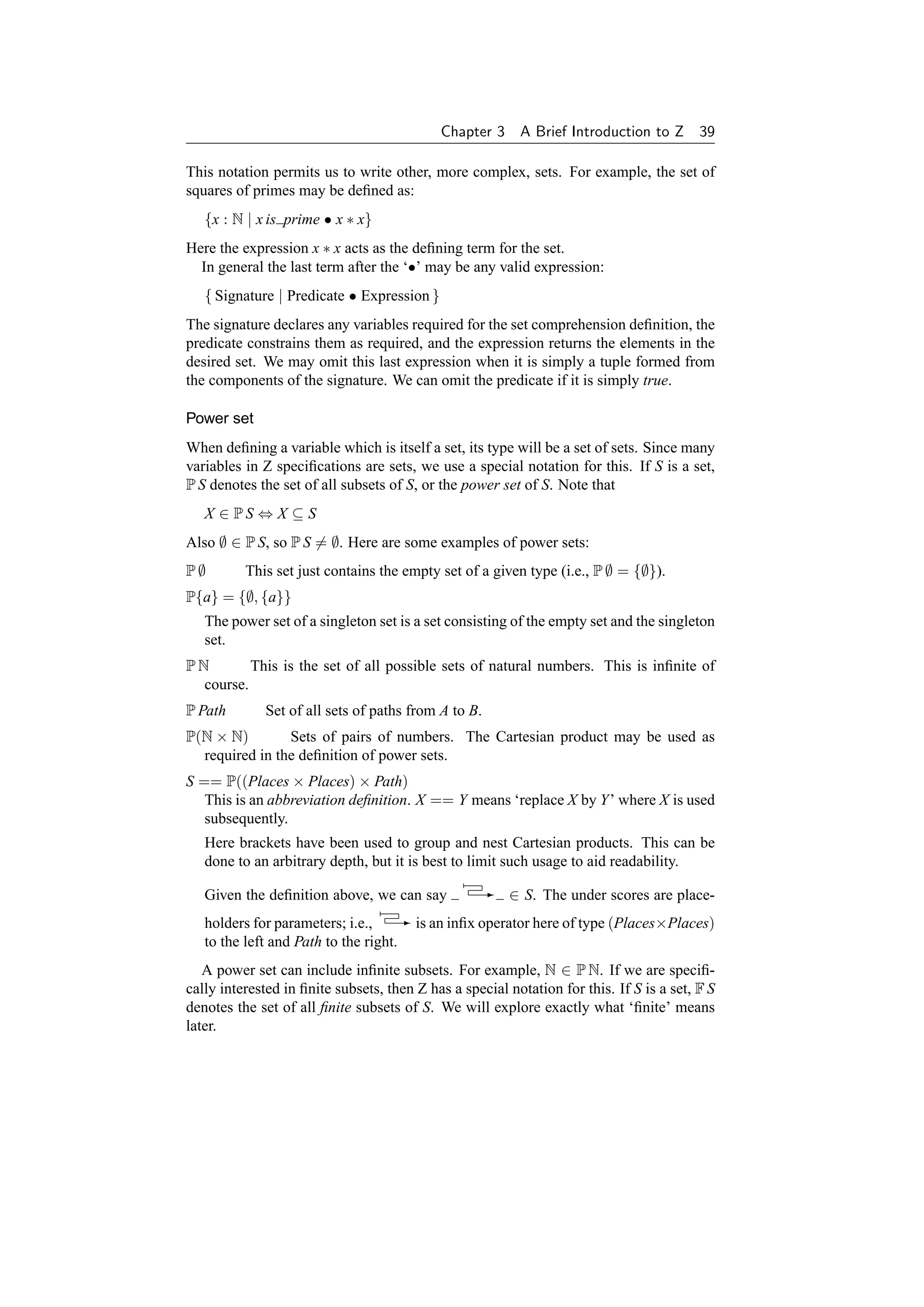


![42 Formal Specification and Documentation using Z
3.4.1 Functions
In Z, functions are a special case of relations in which each element in the domain has
at most one value associated with it. For example, a partial function ‘→’ is defined
using set comprehension in terms of a more general relation ‘↔’ as follows, using an
‘abbreviation definition’:
X → Y ==
{ f : X ↔ Y | (∀ x : X; y1 , y2 : Y •
(x → y1 ) ∈ f ∧ (x → y2 ) ∈ f ⇒ y1 = y2 ) }
I.e., any element x in the domain can only map to a single value in the range of the
function, not to two (or more) different ones. X and Y are identifiers which repre-
sent arbitrary formal generic parameters. These are local to the right hand side of
the definition. → is an infix symbol, and here ‘X → Y’ is actually a short form for
‘( → )[X, Y]’ where the underlines indicate positions of the parameters. The generic
parameters may be explicitly given in square brackets when → and other similar con-
structs are used, but they are normally omitted since in most cases they can be inferred
from the context and clutter the specification unnecessarily.
There are a number of special types of function in Z, each given there own unique
type of arrow. For example, total functions, as indicated by ‘→’ have a domain con-
sisting of all the possible allowed values.
Here is a list of the other standard types of function available in Z:
• X Y – Partial injections, in which there is a one-to-one mapping between ele-
ments in the domain and the range. Different values in the domain map to different
values in the range. Thus the inverse is also a function.
• X Y – Total injections, where the function is a partial injective in which the
domain completely populates the set X. I.e., if a function is defined as f : X Y,
then dom f = X.
• X → Y – Partial surjections, where the range completely populates the set Y. I.e.,
→
if a function is defined as f : X → Y, then ran f = Y.
→
• X → Y – Total surjections, where both the domain and the range completely pop-
→
ulate X and Y respectively. Here, if a function is defined as f : X → Y, then
→
dom f = X and ran f = Y.
• X → Y – Bijections, one-to-one total injective and surjective functions. Again,
with a function defined as f : X → Y, dom f = X and ran f = Y, but in addition,
→
the inverse is also a total function (i.e., f ∼ ∈ Y → X).
• X → Y – Finite partial functions, where the domain of the function (and hence the
also range which can never be larger than the domain for a function) must be finite.
This is a subset of all partial functions on X and Y, and also of F(X × Y).
• X Y – Finite partial injections, which as well as being finite are also one-to-one.
This is the same as the intersection of finite functions and partial injections on X
and Y.
All these different types of function are formally defined on pages 105 and 112 of
[381].](https://image.slidesharecdn.com/zbook-130114070646-phpapp01/75/Zbook-55-2048.jpg)
![Chapter 3 A Brief Introduction to Z 43
Function application is written in the standard mathematical manner in Z; for exam-
ple, f (x) applies the element x to the function f . It is permissible to omit the brackets
if desired; e.g., ‘f x’ is the same as f (x). Brackets should be used in Z when they help
with clarity, and are often omited in practice when they are not necessary.
3.4.2 Toolkit operators
There are many operators on relations and functions which help make up a mathemat-
ical ‘toolkit’ of Z. A widely accepted set of such definitions are presented in full in
[381], together with many relevant laws. These are also summarized as part of the Z
Glossary in Appendix B; in particular, see page 234. However, note that the proposed
Z standard [79] may affect which operators are considered ‘standard’ in future. Some
of the generally accepted main operators are briefly presented informally here:
• id A – Identity relation, in which each element in the domain is mapped onto itself
(and only itself) in the range, and vice versa.
• Q o R – Forward relational composition, where elements that match in the range of
9
the first relation and the domain of the second relation are joined together to form a
new binary relation. In the resulting relation, the domain is a subset of the domain
of the first original relation and the range is a subset of the range of the second
original relation. In Z, this is often just known as ‘relational composition’.
• Q ◦ R – Backward relational composition. This is the same as forward relational
composition with the parameters reversed: R o Q. Forward relational composition is
9
more widely used in Z than backward relational composition for stylistic reasons.
• A R – Domain restriction. The set on the left hand side is used to restrict the re-
sulting relation to be just the mappings in the original relation which have a member
of that set as the first element in each tuple.
• A − R – Domain anti-restriction. Here the complement of the set is used to restrict
the relation.
• R A – Range restriction. This is similar to domain restriction, but the range of the
relation is restricted by the set instead.
• R − A – Range anti-restriction. Hopefully you can work out what this does from
the three previous operators!
• R(| A |) – Relational image. Here the relation R is restricted in a similar manner to
domain restriction
• iter n R – Relational iteration. The relation R is composed n times with itself. This
is often written as Rn in Z for brevity. The relation must have a type-compatible
domain and range (say A). Then iter 0 R (R0 ) is the same as id A, iter 1 R is the
same as R, iter 2 R is the same as R o R, iter 3 R is the same as R o R o R, and so on.
9 9 9
• R∼ – Inverse of relation. All tuples in the relation are reversed. Thus the domain
becomes the range and vice versa. In the case where the domain and range have
the same type (i.e., the relation is homogeneous), this is the same as R−1 , defined
using relational iteration as presented above. More precisely, ∼ may be applied to
any relation R : X ↔ Y, but R−1 may only be used if the relation R has a type of
the form X ↔ X.](https://image.slidesharecdn.com/zbook-130114070646-phpapp01/75/Zbook-56-2048.jpg)


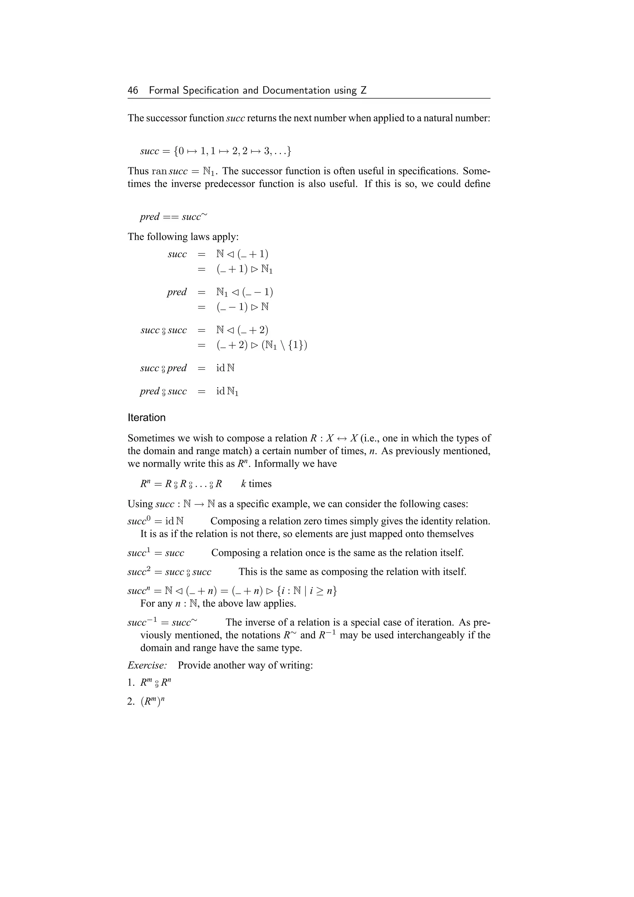
![Chapter 3 A Brief Introduction to Z 47
Number range
A number range (a set of numbers) between two integers a, b : Z is denoted as
a . . b = {a, a + 1, a + 2, . . . , b − 2, b − 1, b}
or more formally
a . . b = {n : Z | a ≤ n ≤ b}
If a b then a . . b = ∅. Also a . . a = {a}.
Cardinality
The cardinality of a (finite) set is the number of elements in that set, or the size of the
set. The cardinality of a set s ∈ F T (the set of all finite subsets of T – see page 39) is
denoted:
#s
Thus #∅ = 0, #{a} = 1, #{a, b} = 2 (if a = b) and so on. For a number range
a . . b,
#a . . b = 1 + b − a if a ≤ b
= 0 if a b
= max{0, 1 + b − a}
For a set to be ‘finite’, it must be possible to map from a natural number in the range
1 . . n uniquely onto each element in that set. n is then the cardinality or size of the
set. This mapping can be done with a suitable finite partial injective function. For
example, the set a . . b (where a ≤ b) may be mapped using the function f : N Z
such that f = succa−1 a . . b. The range (ran f ) is a . . b, and the domain (dom f ) is
a − (a − 1) . . b − (a − 1) or 1 . . 1 + b − a. Thus the cardinality is 1 + b − a, as stated
above.
Pictorially we have:
1 2 3 ··· b − a 1 + b − a
– – – ··· – –
↓ ↓ ↓ ↓ ↓
a a + 1 a + 2 ··· b − 1 b
3.5.2 Types revisited
In Z, integers (Z) are normally supplied as a basic type (although see below) together
with standard arithmetic operators. The natural numbers N (0, 1, 2 . . .) are defined as a
subset of the integers. Thus it is not a true type; rather the type of n : N is Z and n has
the extra constraint that it must be greater than or equal to zero. For more information
on determining types, see the beginning of Chapter 2 in [381].
By convention, R is sometimes used to denote real numbers if these are needed
[411], although these are not defined in Spivey’s Z toolkit [381]. They may be defined
in the proposed Z standard [79]. However many applications for which Z is used do
not involve real numbers. As well as numbers, we can also define our own types.
Sometimes we are not particularly interested in the exact values of a set, just the](https://image.slidesharecdn.com/zbook-130114070646-phpapp01/75/Zbook-60-2048.jpg)
![48 Formal Specification and Documentation using Z
fact that it exists. We introduce such sets as a basic type (or given set):
[ Places ]
or for several sets,
[ A, B, C ]
If one particular place is of interest, we could define
London : Places
or for more than one place (for example):
Oxford, Cambridge : Places
Oxford = Cambridge
It is important to specify that Oxford = Cambridge here if we want to ensure that the
two are distinct. Otherwise they could be the same place with different names (heaven
forbid!).
If we wish to be more precise we can use a data type definition. For example,
Methods could be defined as
Methods ::= Z | VDM | RAISE | B-Method
Here, the type Methods may take one of four unique values. More complicated data
types are possible. For example, we could define
N ::= zero | succ N
This is equivalent to defining
[N]
zero : N
succ : N N
{zero} ∩ ran succ = ∅
{zero} ∪ ran succ = N
Functions such as succ here are known as constructors. Such complications are
often not needed for many specifications. You are referred to Section 3.10 starting on
page 82 of [381] for more information on such free type definitions.
Question: What is the type of {i, j : N | i j} ?
3.5.3 Sequences
Lists, arrays, files, sequences, trace histories are all different names for a single im-
portant data type. The important characterization is that the elements are indexed and
normally contiguously numbered.
Consider how we might store, for any pair (A, B) ∈ Places × Places, the least cost
paths from A to B, (i.e., the relation (A, B) - path). A common way to do this is](https://image.slidesharecdn.com/zbook-130114070646-phpapp01/75/Zbook-61-2048.jpg)
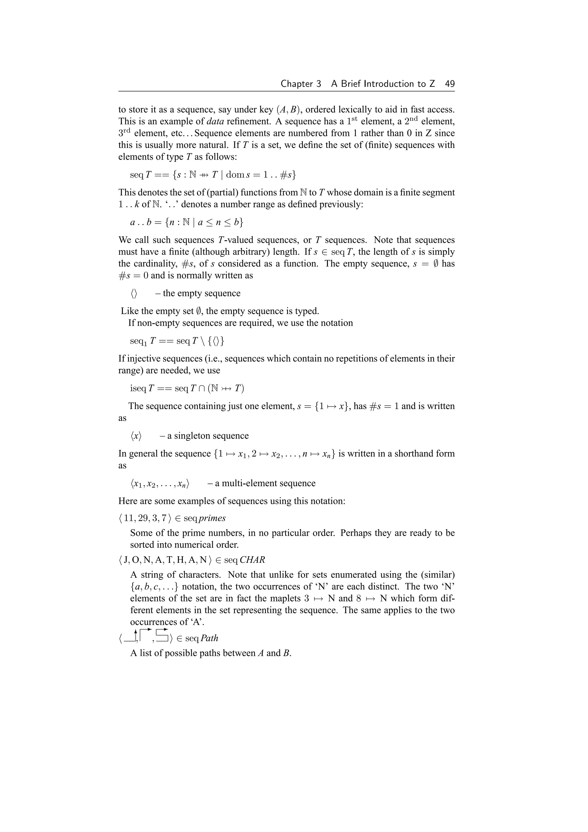
![50 Formal Specification and Documentation using Z
The length (and thus cardinality) of the three sequences above is 4, 7 and 3 respec-
tively.
Note that unlike sets, sequences can have several repeated elements. E.g.:
Emma = Emma, Emma, Emma
Also, the order is significant:
Alice, Emma = Emma, Alice
Concatenation
We concatenate sequences s, t ∈ seq T (or append t to the end of s) by
s t – the function 1 . . (#s + #t) → T with elements
s(j) if 1 ≤ j ≤ #s
j→
t(j − #s) if #s j ≤ (#s + #t)
More formally, we could define concatenation as
s t = s ∪ ( − #s) o t
9
For another equivalent definition, see page 116 of [381].
Consider the concatenation of two sequences of length 5 and 3:
s t
Diagrammatically:
s t
#s = 5 #t = 3
Note that #(s t) = #s + #t = 5 + 3 = 8. Here is an examples of concatenation of
sequences:
A L, I, C, E = A, L I, C, E = A, L, I, C, E
So a, b, c, . . . is effectively shorthand for a b c ...
Laws
s = s = s
r (s t) = (r s) t
(r s = r t) ⇒ s = t
Prefix
Note that for s, t ∈ seq T, s ⊆ t is equivalent to ∃ r : seq T • s r = t. Thus ⊆ applied
to a pair of sequences effectively checks that the left hand sequence is a prefix of the
right hand sequence. For example:
M, A ⊆ M, A, N (Freud’s theorem!)
⊆s is always a prefix of any sequence.
s⊆s A sequence is always a prefix of itself.](https://image.slidesharecdn.com/zbook-130114070646-phpapp01/75/Zbook-63-2048.jpg)
![Chapter 3 A Brief Introduction to Z 51
Laws
If one sequence is the prefix of another and vice versa, the two sequences are identical:
(s ⊆ t ∧ t ⊆ s) ⇒ s = t
If a sequence is the prefix of a sequence which is the prefix of yet another sequence,
then the first sequence is also a prefix of this other sequence:
(r ⊆ s ∧ s ⊆ t) ⇒ r ⊆ t
If two sequences are a prefix of another sequence, then one of the two sequences must
be a prefix of the other. Note that these laws also apply to sets:
(r ⊆ t ∧ s ⊆ t) ⇒ (r ⊆ s ∨ s ⊆ r)
In Z, the relation s prefix t, defined in the Z toolkit (page 119 of [381]) can also be
used to check for a sequence prefix.
Other sequence operations
It is often useful to be able to extract the first or last element from a sequence in
specifications. The rest of the sequence may also be of interest. Four functions are
available for these operations. If s ∈ seq T and s = (i.e., s ∈ seq1 T):
head s = s(1) •◦◦◦◦◦ first element of sequence
last s = s(#s) ◦◦◦◦◦• last element of sequence
tail s = succ o ({1} − s)
9 ◦••••• sequence without first element
front s = {#s} − s •••••◦ sequence without last element
It is best to avoid applying these functions to an empty sequence; for example, head
is undefined.
As an example, if the sequence s is C, O, D, E (which is {1 → C, 2 → O, 3 →
D, 4 → E} then
head s = C
last s = E
tail s = {0 → 1, 1 → 2, 2 → 3, 3 → 4, . . .} o {2 → O, 3 → D, 4 → E}
9
= {1 → O, 2 → D, 3 → E}
= O, D, E
front s = {4} − {1 → C, 2 → O, 3 → D, 4 → E}
= {1 → C, 2 → O, 3 → D}
= C, O, D
Exercise: State some laws concerning these operations. Try not to refer to [381]!
We could construct more general versions of front and tail if required for a particular
application, allowing the length of sequence required to be specified, using generic
construction:](https://image.slidesharecdn.com/zbook-130114070646-phpapp01/75/Zbook-64-2048.jpg)
![52 Formal Specification and Documentation using Z
[T]
for ,
after : (seq T) × N → (seq T)
∀ s : seq T; n : N •
s for n = (1 . . n) s ∧
s after n = ({0} − succn ) o s
9
For example, these could be useful in extracting portions of files considered as a se-
quence of bytes. Note that for s ∈ seq1 T,
front s = s for (#s − 1)
tail s = s after 1
Here are some laws:
s for 0 =
s for #s = s
s after 0 = s
s after #s =
Reversal
If s ∈ seq T, the reverse of s is given by rev s. For example, the sequence, D, O, G is
converted to G, O, D using the rev function!
Laws
rev =
rev x = x
rev(rev s) = s
rev(s t) = (rev t) (rev s)
For example
rev( a, b c, d ) = d, c b, a
Distributed operations
Sometimes the concatenation of a sequence of sequences is useful:
/ =
/ a, b, . . . , n = a b ... n
More formally, / : seq(seq T) → seq T satisfies
/( a s) = a ( / s)](https://image.slidesharecdn.com/zbook-130114070646-phpapp01/75/Zbook-65-2048.jpg)
![Chapter 3 A Brief Introduction to Z 53
and also
/(s a ) = ( / s) a
For the actual formal definition of /, see page 121 of [381].
Question: What is rev( / N, A, H , T, A , N, O , J )?
Other distributed operators can also be defined for sequences if required for a particu-
lar specification. For example, a session of updating a database results in a sequence
of partial functions. We could define a distributed overriding operator in terms of the
standard dyadic overriding operator to generalize the overriding of a relation. See for
example, a definition on page 172. Informally:
⊕/ a, b, . . . , n = a ⊕ b ⊕ . . . ⊕ n
Exercise: The composition operator ‘o’ may also be generalized to a distributed com-
9
position operator ‘o/’. Again, informally:
9
o
9/ a, b, . . . , n = a o b o . . . o n
9 9 9
Write a formal definition for this. Can you think of an application for this operator in
a specification?
Disjointness and partitioning
A sequence of sets is considered ‘disjoint’ if none of the sets in its range intersect.
Formally:
∀ S : seq P T •
disjoint S ⇔ (∀ i, j : dom S | i = j • (S i) ∩ (S j) = ∅)
The empty and singleton sequences of sets are always disjoint since there are no two
distinct elements to consider. I.e., disjoint and disjoint x are always true.
For a two-element sequence, disjoint S is equivalent to:
S(1) ∩ S(2) = ∅
For a three-element sequence, disjoint S is
S(1) ∩ S(2) = ∅ ∧ S(2) ∩ S(3) = ∅ ∧ S(3) ∩ S(1) = ∅
and so on.
We can extend this idea to consider the generalized union of all the sets in the range
of the sequence. If it is equal to a particular set, the sequence is said to ‘partition’ that
set. Formally:
∀ S : seq P T; P : P T •
S partition P ⇔ ( disjoint S ∧ P = {i : dom S • S i} )
Disjointness and partitioning may be generalized from sequences to any indexed set
(i.e., S : I → P T instead of S : seq P T).](https://image.slidesharecdn.com/zbook-130114070646-phpapp01/75/Zbook-66-2048.jpg)
![54 Formal Specification and Documentation using Z
3.5.4 Orders
The Z toolkit can be extended as required for a particular application. For example, a
partial order, which is reflexive, antisymmetric, and transitive, may be a useful concept
in some specifications:
partial order[X] ==
{ R : X ↔ X | ( ∀ x, y, z : X •
xRx∧
(x R y ∧ y R x) ⇒ x = y ∧
(x R y ∧ y R z) ⇒ x R z ) }
This can be extended to define a total order, in which all elements are related:
total order[X] ==
{ R : partial order[X] | ( ∀ x, y : X •
x R y ∨ y R x)}
For example, it may be useful to model time as a total order in a particular specifica-
tion.
3.5.5 Summary
We have briefly covered numbers and then used these to define the notion of se-
quences, an important data structure in many specifications and data refinement. We
have also looked at ways in which Z lets us manipulate sequences.
This concludes the introduction to the mathematical notation of Z. Some lesser used
parts of Z (such as bags) have not been covered here, but are included from page 124
onwards in [381]. As you gain confidence in writing Z specifications, you should
investigate these other features of Z.
Using mathematics for specification is all very well for small examples, but for
more realistically sized problems, things start to get out of hand. To deal with this,
Z includes the schema notation to aid the structuring and modularization of specifica-
tions. We have seen an example of a schema box in passing. In the next section we
shall see how to combine such schemas to produce larger specifications.
3.6 Schemas
A boxed notation called ‘schemas’ is used for structuring Z specifications. This has
been found to be necessary to handle the information in a specification of any size.
We saw a brief example on page 32. Here is another example of a schema:
Book
author : People
title : seq CHAR
readership : P People
rating : People → 0 . . 10
readership = dom rating](https://image.slidesharecdn.com/zbook-130114070646-phpapp01/75/Zbook-67-2048.jpg)
![Chapter 3 A Brief Introduction to Z 55
This defines a single author, a book title, and a number of people who make up the
readership of a book (a set of people, as indicated by the ‘power set’ operator P in the
type declaration), together with their rating of the book (out of 10). The bottom half
of a schema optionally introduces extra constraints between the variables in the form
of predicates. Here, the readership is the same as the domain of the rating function.
The top half of the Book schema box defines a number of named variables with
associated constraints from which the type information can be mechanically derived.
Here seq CHAR is a subset of N → CHAR (see the definition of seq on page 115 of
[381]), which itself is a subset of Z ↔ CHAR. This is the same as P(Z × CHAR) (see
page 95 of [381]). The expression 0 . . 10 implies a type of integer Z with the extra
constraint that the rating must take a value between 0 and 10. In fact this schema may
be ‘normalized’ into the following form:
Book
author : People
title : P(Z × CHAR)
readership : P People
rating : P(People × Z)
title ∈ seq CHAR
rating ∈ People → 0 . . 10
readership = dom rating
Note that the predicates on separate lines in the second half of the schema above
are conjoined together by default. Here, the declarations use the most general types
possible for the components. These are the actual types for these components, which
could be used for type-checking purposes if required. Mentally calculating such types
can be a useful aid in understanding a specification.
Schemas are primarily used to specify state spaces and operations for the mathe-
matical modelling of systems. For example, here is a schema called StateSpace:
StateSpace
x1 : S1
x2 : S2
.
.
.
xn : Sn
Inv(x1 , . . . , xn )
This can also be written as follows to save space if desired:
StateSpace
x1 : S1 ; . . . ; xn : Sn
Inv(x1 , . . . , xn )
Even more space can be saved using a horizontal formal of schema definition, which
is typically used if the entire definition can conveniently fit on a single line. E.g.:
StateSpace = [x1 : S1 ; . . . ; xn : Sn | Inv(x1 , . . . , xn )]](https://image.slidesharecdn.com/zbook-130114070646-phpapp01/75/Zbook-68-2048.jpg)
![56 Formal Specification and Documentation using Z
This schema specifies a state space in which x1 , . . . , xn are the state variables and
S1 , . . . , Sn are expressions from which their types may be systematically derived. Z
types are sets – x1 , . . . , xn should not occur free in S1 , . . . , Sn , or if they do, they refer
instead to other occurrences of these variables already in scope (e.g., globally defined
variables). Inv(x1 , . . . , xn ) is the state invariant, relating the variables in some way for
all possible allowed states of the system during its lifetime.
Note that unlike in an ordered tuple, the variables in a schema are essentially un-
ordered – reordering them would give the same schema – and the variable names do
not come into scope until the bottom half of the schema. Thus any interdependencies
must be defined here. (A common mistake by initial users of Z is to define interdepen-
dencies in the declaration part, but a type-checker will very quickly detect this.)
3.6.1 Example specification
The ‘Birthday Book’ is a well known example from Chapter 1 of Spivey’s widely used
book on Z [381]. It is a system for recording birthdays. It uses the following basic
types (or given sets):
[NAME, DATE]
The state space of the Birthday Book is specified by:
BirthdayBook
known : P NAME
birthday : NAME → DATE
known = dom birthday
The state variables are known (a number of people’s names) and birthday (unique
dates associated with each known person’s name). The ‘invariant’ property of this
schema is:
known = dom birthday
I.e., every known person has a birth date associated with them.
Z makes use of identifier decorations to encode intended interpretations. A state
variable with no decoration represents the current (before) state and a state variable
ending with a prime ( ) represents the next (after) state. A variable ending with a
question mark (?) represents an input and a variable ending with an exclamation mark
(!) represents an output. A typical schema specifying a state change is the following
operation schema:](https://image.slidesharecdn.com/zbook-130114070646-phpapp01/75/Zbook-69-2048.jpg)
![Chapter 3 A Brief Introduction to Z 57
Operation
x1 : S1 ; . . . ; xn : Sn
x1 : S1 ; . . . ; xn : Sn
i1 ? : T1 ; . . . ; im ? : Tm
o1 ! : U1 ; . . . ; op ! : Up
Pre(i1 ?, . . . , im ?, x1 , . . . , xn )
Inv(x1 , . . . , xn )
Inv(x1 , . . . , xn )
Op(i1 ?, . . . , im ?, x1 , . . . , xn , x1 , . . . , xn , o1 !, . . . , op !)
The inputs are i1 ?, . . . , im ?; the outputs are o1 !, . . . , op !; the precondition is:
Pre(i1 ?, . . . , im ?, x1 , . . . , xn )
The state change (x1 , . . . , xn ) to (x1 , . . . , xn ) is specified by:
Op(i1 ?, . . . , im ?, x1 , . . . , xn , x1 , . . . , xn , o1 !, . . . , op !)
Note that before and after states which are not constrained may take any allowed
value. Thus, unlike most programming languages, after states are unconstrained by
their matching before states unless explicitly stated to do so. Thus it is necessary to
include the predicate x1 = x1 if x1 is to retain the same value after the operation.
This convention can be confusing to some programmers, but is extremely useful in
specifications. If required, there is a convention for constraining a number of state
components to remain the same, as we shall see shortly.
As a more specific example of a operation schema, consider the adding of a birthday
to the birthday book:
AddBirthday
known : P NAME
birthday : NAME → DATE
known : P NAME
birthday : NAME → DATE
name? : NAME
date? : DATE
name? ∈ known
/
known = dom birthday
known = dom birthday
birthday = birthday ∪ {name? → date?}
The entire state with its invariant is repeated for both the before (undashed) and after
(dashed) states. Fortunately schemas may be ‘included’ in other schemas, so this may
be written much more concisely than above in a real specification, reducing six lines to
a single included schema in the specification above in Spivey’s original specification
(see page 4 of [381]).](https://image.slidesharecdn.com/zbook-130114070646-phpapp01/75/Zbook-70-2048.jpg)
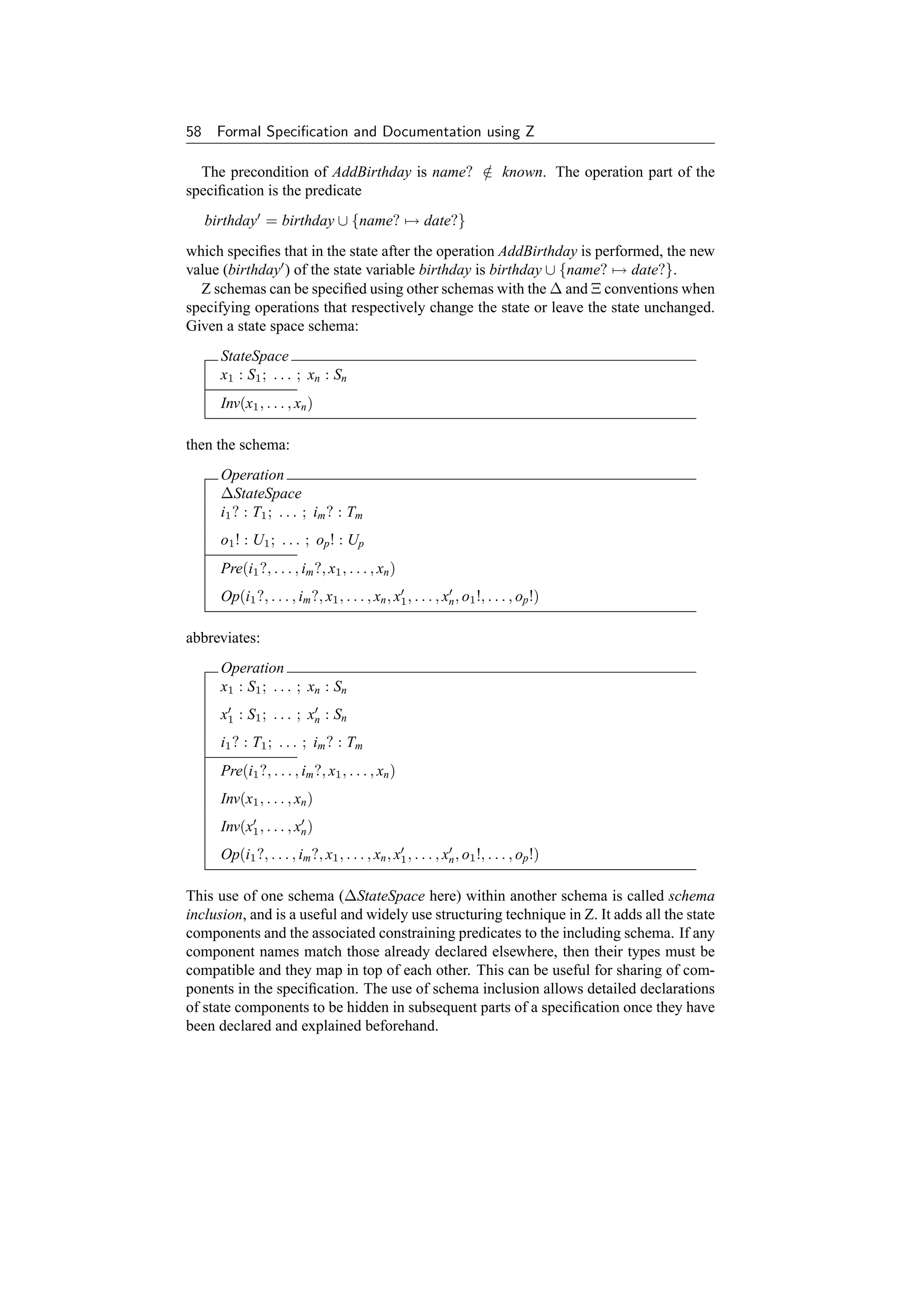


![Chapter 3 A Brief Introduction to Z 61
3.6.2 Schema operators
There are schema operators matching the logical connectives on predicates, such as
¬ , ∧, ∨, ⇒ and ⇔, as well as quantification using ∀, ∃ and ∃1 . The schemas are
first normalized. For the binary connectives to be used, there must be no conflicting
declarations in the schemas being combined. For schema negation, the normalization
is particularly important to ensure any hidden predicate constraints in the declarations
are also negated. For binary operators, the declarations are merged in the resulting
schema (remember that the order of the declarations is not important) and the predicate
parts are combined depending on the operation involved. See [200] for a discussion of
the issues involved, and pages 32 to 34 of [381] for further explanation and examples.
It is possible to declare a schema as a type (e.g., state : StateSpace). If such a dec-
laration is in scope then a component may be selected from the schema. For example
state.x1 would return the component x1 , and so on.
It is also useful to return a schema tuple,tuple:of a schema which is similar to an
ordered tuple, except the components are unordered, and named instead. The notation
θStateSpace is used to return the schema tuple for the StateSpace, for example. All
the named components x1 , . . . , xn are included in the schema tuple. As an example, a
schema following the Ξ convention may be defined as follows:
ΞStateSpace = [∆StateSpace | θStateSpace = θStateSpace]
One or more components of a schema may be hidden (i.e., existentially quantified)
using a schema hiding. For example, StateSpace (x1 , x2 ) is the same as ∃ x1 :
S1 ; x2 : S2 • StateSpace.
Conversely, schema components can be projected using components defined by
a second schema using schema projection. For example, if ProjectSpace = [x1 :
S1 ; x2 : S2 ] then StateSpace ProjectSpace hides all the components of StateSpace
except x1 and x2 .
Components of a schema may be renamed using schema renaming. For example,
StateSpace[y1 /x1 , y2 /x2 ] returns a new schema with the x1 component replaced by y1
and the x2 component replaced by y2 . This can be useful if there is a clash of names
in a specification for some reason.
Z provides a ‘pre’ operator which may be used to return the precondition of a
schema. pre Operation existentially quantifies all after state and output components.
I.e.,
∃ x1 : S1 ; . . . ; xn : Sn ; o1 ! : T1 ; . . . ; op ! : Tp • Operation
Another more complicated schema operation is sequential composition (‘o’). If
9
Operation1 and Operation2 are two operation schemas such as:
Operation1
x1 : S1 ; . . . ; xp : Sp
z1 : U1 ; . . . ; zn : Un
z1 : U1 ; . . . ; zn : Un
Op1(x1 , . . . , xp , z1 , . . . , zn , z1 , . . . , zn )](https://image.slidesharecdn.com/zbook-130114070646-phpapp01/75/Zbook-74-2048.jpg)
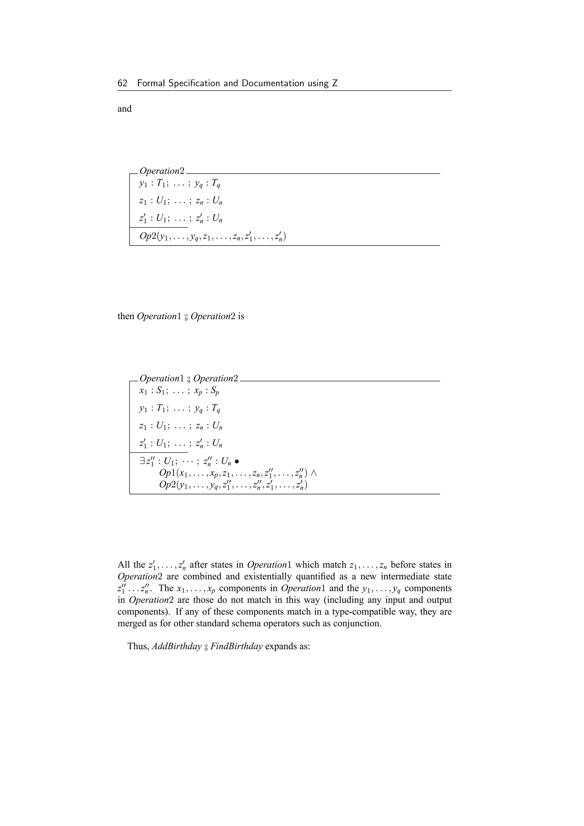
![Chapter 3 A Brief Introduction to Z 63
AddThenFindBirthday
known : P NAME
birthday : NAME → DATE
known : P NAME
birthday : NAME → DATE
name? : NAME
date? : DATE
date! : DATE
∃ known : P NAME; birthday : NAME → DATE •
known = dom birthday ∧
known = dom birthday ∧
name? ∈ known ∧
/
birthday = birthday ∪ {name? → date?} ∧
known = dom birthday ∧
known = known ∧
birthday = birthday ∧
name? ∈ known ∧
date! = birthday (name?)
There is a similar schema piping operator in Z which matches the outputs of the first
schema to the inputs of the second schema instead of the state components.
3.6.3 Properties
An example of a simple property that one might want to prove is:
AddThenFindBirthday date! = date?
I.e., a FindBirthday operation after an AddBirthday, with the same name input to both,
outputs the same date as that input to the AddBirthday operation. This is the sort of
property that, if proved, provides an extra level of confidence that a specification is
correct, since it confirms our intuitions about the properties of the specifications that
we expect to hold. If a given desired property cannot be proved, this may well indicate
a flaw in the specification, which can then be rectified at an early stage before any
implementation has been started. Using informal design techniques, such errors are
not normally discovered until a later stage, such as coding, testing, or even after the
system has been delivered, with all the extra costs that this involves.
Note that Z as defined by Spivey [381] includes no standard way to write theo-
rems. In this book, we adopt the convention of writing p where p is some predicate.
Alternatively, d p is sometimes used to include universally quantified declarations
d.
3.7 Conclusion
This chapter has provided an extremely brief introduction to Z. Readers who still have
reservations about their understanding of Z would be well advised to read an introduc-](https://image.slidesharecdn.com/zbook-130114070646-phpapp01/75/Zbook-76-2048.jpg)
![64 Formal Specification and Documentation using Z
tory textbook on Z before tackling the formal case studies presented in the rest of this
book. See page 244 for a list of such books.
The Z notation includes set-theoretic definitions in the form of an extensive mathe-
matical ‘toolkit’ as comprehensively presented in [381]. Much of Z as it is normally
used is defined using itself in this toolkit, and it is forming the main basis for the
proposed Z standard [79]. In addition, in may be desirable to create further toolkit
libraries for certain applications. For example, the inclusion of real numbers has been
considered [411].
It is important to remember than Z is based on first order logic. A common mistake
of novice Z users is to attempt to form relations and functions on predicates. This is
not legal in Z. In fact there is no predefined Boolean type in Z since it is normally
unnecessary. It is possible to define a binary valued type in Z if required, but often
there is a better way of approaching the specification if a developer finds him/herself
tempted to do this, unless it is explicitly needed in a certain application (e.g., see
Chapter 8). A Z type-checker will quickly discover any attempt by a specifier to bend
the rules of Z and try to use it in a higher order manner, as in HOL [178] for example.
However, unfortunately there are some untype-checked Z specifications are incorrect
because of this problem.
Z has been a relatively fluid language during its lifetime. The lack of tools in the
early days of its development was a positive asset since it allowed new ideas to be tried
experimentally with little overhead. However as Z has become more established, and
used increasingly in industry, the need for a standard notation to allow mechanical tool
support has increased. The current de facto standard widely used by academics and
industrial users alike, is that laid down in Spivey’s Z Notation: A Reference Manual
(often know as the Z Reference Manual, or ‘ZRM’ for short). This is now in its 2nd
edition [381]. This is the notation generally used in this book. The development
of an international Z standard is in progress [79]. Once this is accepted it is likely
to supersede [381] since tool builders will probably then adopt it as the notation of
choice.
This completes the introductory part of the book. As previously mentioned, a com-
prehensive introduction to Z is impossible in a single chapter. If you still require
further grounding in the use of Z, please consult one or more of the numerous Z text-
books available (as listed on page 244) before proceeding with the rest of the book.
Subsequent the chapters present a number of case studies of specifications in Z, nearly
all of implemented (and hopefully useful!) systems.](https://image.slidesharecdn.com/zbook-130114070646-phpapp01/75/Zbook-77-2048.jpg)


![Chapter 4
Documentation using Z
The Z notation has been applied to the formal specification of resource managers
or ‘services’ within a distributed system. A formal description gives a more precise
understanding of the behaviour of a service and, when combined with informal text,
is sufficiently readable for the specification to be used for documentation purposes.
Two types of manual have been produced, one presenting the external view of the
service (for users) and another describing the internal view (for implementors).
A common service framework deals with standard aspects of services. Parts of a
simple User and Implementor Manual are presented as an example.
4.1 Introduction
The aim of this chapter is to introduce and illustrate a formal style of specifying and
documenting system components. The components considered in the study are ser-
vices within a distributed computing system [57].
First an introduction to the style of specification is presented. It considers how a
service can be modelled in the Z specification language, and the way in which such
specifications can be used in documenting both the user’s and the implementor’s view
of a service. Next an example of a service specification is given. This example de-
scribes a very simple service, the Reservation Service, and serves to demonstrate the
style of User Manual developed by the project. Additionally a simple example of an
implementation-oriented specification in the form of an Implementor Manual for the
Reservation Service is presented. Finally some experience gained from the work is
discussed.
More complex services have been documented and implemented but these are not
presented here to keep the length to a manageable size. Chapter 5 presents a single
more realistically sized manual.
The Reservation Service was developed as a part of the Distributed Computing Soft-
ware (DCS) Project at the Programming Research Group within the Oxford University
Computing Laboratory. The goal of the project was to investigate the use of formal
techniques in the design and documentation of services for a loosely-coupled dis-
tributed operating system, based on the model of autonomous clients having access to
a number of shared facilities. Several services have been designed and documented in
the manner described here, and implementations of them have been provided for, and
used by, members of the Programming Research Group.
67](https://image.slidesharecdn.com/zbook-130114070646-phpapp01/75/Zbook-80-2048.jpg)
![68 Formal Specification and Documentation using Z
A number of monographs were produced by the project [55, 56, 172]. These pro-
vide more information for those interested in the details of the work of the project.
In particular, the User and Implementor Manuals for the Reservation Service and a
(much larger) Block Storage Service, together with the Common Service Framework,
covering standard facilities such as authentication and accounting, are presented in
their entirety.
4.2 Motivation
It is fundamental to the design of any complex artefact, and of computer systems in
particular, that an appropriate means of describing and communicating the design is
used.
A very important line of communication is between the designer and the user of the
system. It is only if this communication is accomplished satisfactorily that the designer
can have any expectation of meeting the requirements of the user and, likewise, the
user have any expectation of being able to make proper use of the finished product.
No less important is the communication from the designer to the implementor of
the system. This is necessary to ensure that the finished product does indeed have the
characteristics that the designer specified.
The aim of the work described here is the improved communication between de-
signer, user and implementor which can be achieved by the use of formal specification
in the design and documentation of computer systems.
4.2.1 Formal specification
Satisfactory communication relies firstly on the production of an unambiguous de-
scription. If a description is sufficiently precise, it can act as a contract between the
designer, user and implementor, to ensure that they agree on what is to be provided.
A fundamental objective of the Distributed Computing Software Project has been
to make use of mathematical techniques for program specification to assist the design,
development and presentation of distributed system services.
The formal notation Z was used throughout the project. The Distributed Computing
Software Project tested the application of the theoretical ideas behind Z to a realistic
and practical system. As a result of this, the project was influential in the development
of notational techniques which have now become a standard part of the Z style of
specification.
The use of formal specification techniques, because of their rigour, tends to guide
designs towards the conceptually simple. This has the advantage of making the designs
easier to understand, but the possible disadvantage of making them harder to imple-
ment efficiently, since the simplest ideas do not necessarily have the most straightfor-
ward realization.
Formal techniques encourage a level of abstraction that is important in avoiding
the introduction of unnecessary implementation bias into designs. In the initial de-
sign, implementation bias simply restricts the range of possible implementations. It is
usually an indication that the designer allowed unnecessary knowledge of a potential
implementation to become visible at the user level.](https://image.slidesharecdn.com/zbook-130114070646-phpapp01/75/Zbook-81-2048.jpg)


![Chapter 4 Documentation using Z 71
AOP
User view: AS - AS
Rel Rel
COP
Implementor view: CS - CS
Figure 4.1 Relationship between abstract and concrete views.
operation COP must, given an initial state CS which relates to AS according to Rel,
produce a new state CS which relates to AS according to Rel . This can be expressed
more formally as:
∀ AS; CS • pre AOP ∧ Rel ⇒ pre COP
∀ AS; CS; CS • pre AOP ∧ COP ∧ Rel ⇒ (∃ AS • AOP ∧ Rel )
Note that input and output variables have been ignored in the above for simplicity of
presentation. For a fuller treatment, see page 138 of [381].
The ‘pre ’ schema operator gives the precondition of a schema in which all the after
(dashed) state and output components (ending with ‘!’) are existentially quantified.
The concrete state is thus considered as a data refinement of the abstract state, and
each of the concrete operations must model the same behaviour on the concrete state
as the corresponding abstract operation does on the abstract state.
The relationships between the two models can be illustrated as in Figure 4.1.
4.4 Service Documentation
In this section an outline of the structure adopted for the documentation of a service
is presented. The documentation consists of two main parts, a User Manual and an
Implementor Manual.
The manuals use Z throughout, and thus some effort is still required to transform the
presented implementation into final code. Note that an Implementor Manual presents
only one possible implementation, reflecting a particular set of design decisions. A
programmer could choose to implement a service differently, provided it still satisfied
the specification given in the user manual.
As an illustration of the manual style adopted by the project, some extended excerpts
from the manuals for a very simple service are now presented. Occasional footnotes
have been added to aid those not familiar with the Z notation. Some familiarity with set
theory and first order predicate calculus (upon which Z is based) is assumed. Reading
an introductory textbook such as [336] or one of those listed on page 244 beforehand
is recommended if possible.](https://image.slidesharecdn.com/zbook-130114070646-phpapp01/75/Zbook-84-2048.jpg)
![72 Formal Specification and Documentation using Z
The manuals make use of some definitions from the Common Service Framework.
In particular, some given sets of data values are not formally elaborated further:
[UserNum, Report]
UserNum is the set of numbers which identify system users; Report is the set of re-
ports showing the outcome of an operation. Two individual unique special users are
assumed:
ManagerNum, GuestNum : UserNum
ManagerNum = GuestNum
ManagerNum is the identity of the manager of a service; GuestNum is the identity
of the guest (unauthenticated) user.
Time and intervals of time may be modelled are natural numbers for convenience,
to allow standard arithmetic operations to be available on them:
Time == N
Interval == N
ZeroInterval == 0
Time is the set of date/time instants and Interval is the set of time intervals between
such instants. ZeroInterval is a interval with no duration.
4.5 Reservation Service – User Manual
The Reservation Service allows clients to notify a manager how long they may require
use of a system resource such as another service. A client may make a reservation for
a specified period. Subsequently the reservation may be cancelled by the holder by
requesting a reservation of zero interval. At any one time, there may be a number of
client reservations.
The service manager may inspect the reservations whenever required. The man-
ager may also set a shutdown time after which the availability of the resource being
managed is no longer guaranteed (for example, because of maintenance). If any client
reservations are threatened by the shutdown time, the manager will be notified, and
can then negotiate with the clients concerned or set a new shutdown time. Note that a
client cannot make a reservation past the current shutdown time.
Normally a client will make a reservation for some reasonable period before using
the managed resource. However a client may still use the resource without making a
reservation. In this case there is no guarantee about the availability of the resource.
4.5.1 Service state
A reservation records the user number (public identity) of the client who made it and
the time at which it will expire. A number of reservations may exist at any one time.
Each user may only have one reservation, and there is a limit on the total number of
reservations (Capacity).
Capacity : N1](https://image.slidesharecdn.com/zbook-130114070646-phpapp01/75/Zbook-85-2048.jpg)

![74 Formal Specification and Documentation using Z
conventionally indicates a change of state in Z. Here ∧ is being applied to schemas
and acts in much the same way as schema inclusion as described previously.)
Some operations may leave the state of the service unchanged.
ΞRS = [ ∆RS | θRS = θRS ]
(Again, the use of Ξ is a convention. θ indicates a tuple formed from a schema’s
components. Here the definition could be omitted since this is the default definition
assumed by a Z specification if no explicit definition is made.)
Operations can return finite sets of users, the following definition is made for the
convenience of subsequent specifications:
Users == {u : F UserNum | #u ≤ Capacity}
4.5.3 Reports
There are a number of possible error reports from the operations, all of which have
different values:
SuccessReport,
NotAvailableReport,
TooManyUsersReport,
NotManagerReport,
NotKnownUserReport : Report
SuccessReport, NotAvailableReport, TooManyUsersReport,
NotManagerReport, NotKnownUserReport ∈ iseq Report
The report! output parameter of each operation indicates either that the operation
succeeded or suggests why it failed.
Success indicates successful completion of an operation.
Success
report! : Report
report! = SuccessReport
If a reservation cannot be made due to early shutdown, the shutdown time itself is
returned in until!. Note that a reservation of zero interval will not cause this error.
NotAvailable
ΞRS
interval? : Interval
until! : Time
interval? = ZeroInterval
shutdown now + interval?
until! = shutdown
report! = NotAvailableReport](https://image.slidesharecdn.com/zbook-130114070646-phpapp01/75/Zbook-87-2048.jpg)


![78 Formal Specification and Documentation using Z
4.5.5 Service charges
The basic parameters are supplemented by two hidden parameters, an operation iden-
tifier op? and the cost of executing the operation cost!. The latter can conveniently be
defined in terms of natural numbers.
[Op]
Money == N
ΦParams
ΦBasicParams
op? : Op
cost! : Money
There is a fixed cost for each different successful operation. All clients who make a
reservation will also be charged an amount depending on the requested interval.
ReserveOp, SetShutdownOp, StatusOp : Op
ReserveCost, TimeCost, SetShutdownCost,
StatusCost, ErrorCost : Money
ReserveOp, SetShutdownOp, StatusOp ∈ iseq Op
RSTariff
ΦParams
interval? : Interval
op? = ReserveOp ⇒ cost! = ReserveCost + (TimeCost ∗ interval?)
op? = SetShutdownOp ⇒ cost! = SetShutdownCost
op? = StatusOp ⇒ cost! = StatusCost
If an error occurs, a fixed amount may still be charged.
ErrorTariff = [ ΦParams | cost! = ErrorCost ]
These two schemas combine to form an overall ‘tariff’ schema.
ΦRSTariff = Success ⇒ RSTariff ∧ ¬ Success ⇒ ErrorTariff
4.5.6 Complete service
The definition of the Reservation Service is completed by combining the definitions
of the Reserve operation with the other operations and the tariff schema. In addition,
components from the Common Service Framework are included to handle the service
clock, accounting and statistics. Finally, the effect of invoking a non-existent service
operation, or of a network error are specified.
The additional components needed to define the complete service are omitted in this
overview but may be found in [55].](https://image.slidesharecdn.com/zbook-130114070646-phpapp01/75/Zbook-91-2048.jpg)

![80 Formal Specification and Documentation using Z
cRS
shutd : Time
users : UserArray
times : TimeArray
(users − {Unused}) ∈ (Index UserNum)
(− performs range anti-restriction of a function (in this case, all Unused entries are
removed from the users array), and indicates a partial injection or one-to-one func-
tion.)
Each authentic client can have at most one entry in the users array, all other entries
being unused.
Initially the shutdown time has the default value and all the entries in the user array
are unused. (It will not matter what values are held in the time array.)
cInitRS
cRS
shutd = InitShutdownTime
users = (λ s : Index • Unused)
Operations may change the state of the Reservation Service implementation:
∆cRS = cRS ∧ cRS ∧ ΦBasicParams
Some operations may leave the state of the service unchanged:
ΞcRS = [ ∆cRS | θcRS = θcRS ]
This completes the specification of the concrete state, its initialization. and its change
of state in general terms.
4.6.2 Operation implementations
The four service operations are redefined in this manual in terms of the refined con-
crete state. As in the User Manual, the description of each operation has three sections,
entitled Abstract, Definition and Reports.
Each schema definition may be conveniently implemented as a procedure in the
final program. Again, only the definition of the Reserve operation is included here.
Note that the TooManyUsers report schema has been directly incorporated in the im-
plementation of this operation.
The other error reports remain similar, except that the abstract state is replaced by
the concrete state:](https://image.slidesharecdn.com/zbook-130114070646-phpapp01/75/Zbook-93-2048.jpg)


![Chapter 4 Documentation using Z 83
4.7 Experience
The Reservation Service is one of a number of services designed by the project. Other
services include a Time Service, a Block Storage Service and a File Service. Ser-
vices can act as clients to other services if required. For example, the File Service is
designed to make use of the Block Storage Service. Each service is designed to be
simple and to perform one function. Taking the File Service again, this does not sup-
ply human readable file names or any file organization. If this is needed, a Directory
Service could be used.
This section details some of the experiences of the project. Problems and advantages
of using formal methods, and Z in particular, are discussed.
4.7.1 Manual format
The style of the User Manuals has evolved during the project. For comparison, an
earlier version of the Reservation Service is presented in [203]. Since then, error
conditions have been more exactly specified in the Reports section for each operation,
using the schema overriding operator (⊕) to define an order of checking for error
conditions:
S ⊕ T = (S ∧ ¬ pre T) ∨ T
The cost of performing operations has been gathered together in a tariff schema
after the operations themselves have been presented. The cost of an operation is of-
ten of secondary interest to understanding what the operation does, and clutters its
specification.
At the end of each manual, the operations specific to the service are combined
with those incorporated from the Common Service Framework to produce an overall
specification of the operations available in the service.
The initial state is now included formally for each service. The state of a service at
any given time is the result of the initial state transformed by all the operations which
have been performed to date.
4.7.2 Service implementation
With the introduction of Implementor Manuals, it has been possible to present an
implementor’s view of a service, showing how the abstract user’s view can be refined
towards a concrete implementation.
A significant amount of effort has been spent on the presentation of these manuals,
since it is all too easy for them to become swamped by detail. The implementor manual
for the Reservation Service, included here, is a relatively straightforward example
because of the simplicity of the service itself. For a more realistically sized service,
the reader is referred to [172] and to Chapter 5.
The ultimate goal of such specifications is to consider the refinement of the imple-
mentation of a service all the way down to the code of a particular programming lan-
guage. Refinement, though better understood in theory [208, 230, 299], still requires
the development of styles and techniques to manage the necessary mathematical ma-
nipulations in practice [295]. There has been much work on operation refinement](https://image.slidesharecdn.com/zbook-130114070646-phpapp01/75/Zbook-96-2048.jpg)
![84 Formal Specification and Documentation using Z
using Z [171, 246, 248, 308, 400, 423, 429, 431, 440, 441] and also data refinement
[208, 238, 294]. Parallel refinement, linked with CSP [215], has also been consid-
ered [427, 438], as have object-oriented aspects [19, 257, 420]. The correctness of
real programming languages, such as Ada, with respect to a Z specification is also
an important issue [366]. In the case of safety-critical applications, timing can be-
come an important issue for hard real-time systems where it is an essential part of the
specification that the deadlines be met [271, 272].
Work at Oxford and elsewhere has considered the step from specification into pro-
gramming language in more detail [295, 299]. For example, the Reserve operation has
been systematically refined into Dijkstra’s language of weakest preconditions [296].
The DCS project concentrated on the ‘architectural’ aspects of system design, taking
a top-down approach in which the structure of the implementation was of greatest
concern.
4.7.3 Representation of parameters
The types of parameters of service operations have been presented as Z sets. These
can either be given sets, assumed to be unstructured, such as Time or Report, or they
can be defined in Z as a set, sequence or other more complicated structure.
The issue of how such types will be represented in a specific programming language
has been postponed. Clearly, at the lowest level, the parameter values must be trans-
mitted over the network between client and service in some bit pattern. Since there is
no assumption that all client applications and service code will be written in the same
programming language, there would need to be a clear specification of the representa-
tion at this level so that data conversion functions could be applied if necessary.
Take, as an example, the set of Reservations which is returned by the Status oper-
ation of the Reservation Service. This consists of a partial function (of limited size)
from UserNum to Time. Most programming languages would not be able to implement
this directly. Typically it could be implemented as an array with elements consisting
of a record containing a user number and associated time. The ordering of the array
could be arbitrary, or it may be ordered by user number or time.
Parameter refinement is an important topic which has received relatively little at-
tention [355]. It could be considered as a relation between abstract and concrete pa-
rameters in a similar manner to the way abstract and concrete states are related. It
would therefore form a second, orthogonal, dimension of refinement to that of the im-
plementation of a service. It is crucial to investigate techniques that help avoid errors
at interfaces since this is the point at which many problems that are difficult to detect
beforehand occur.
4.7.4 Common service framework
The introduction of the Common Service Framework allows a number of definitions
common to several services to be grouped together in one document. This means that
the specifications of individual services can be made that much simpler.
The specification of the common service framework has illustrated how separate
subsystems can be defined, with their own state and operations, and then incorporated
into the definition of a complete service. It has addressed, at the specification level,](https://image.slidesharecdn.com/zbook-130114070646-phpapp01/75/Zbook-97-2048.jpg)

![86 Formal Specification and Documentation using Z
sensible approach is to return some standard error value in these cases. Output param-
eters may be checked for this value by the client if desired.
4.7.7 A problem discovered
The Reservation Service was one of the first services to be implemented, and its origi-
nal User Manual has been published previously [173, 174, 203]. However an error was
discovered during the use of the service which was not anticipated during the design
stage. This has led to a small revision in the specification of one of the error schemas
for the service.
The problem arose when a client made a reservation successfully and subsequently
tried to clear it by making a reservation of zero-interval in the normal way. However
the service reported that it was ‘Not Available’ and hence the reservation could not be
removed.
The specification in the User Manual was examined to see how this state of affairs
might transpire. To obtain the ‘Not Available’ report, the following precondition in the
NotAvailable schema had to hold:
shutdown now + interval?
With interval? being zero, this implied that the shutdown time was set earlier than the
current time. Given that the client had earlier successfully made a reservation that was
still in force (and hence needed to be cleared), this implied that the shutdown time had
been brought forward by the service manager, threatening the pending reservation. In
fact, the client was a laser printing service which was known always to make half-hour
reservations. The manager had set a shutdown time earlier than the end of the print-
ing service’s reservation time, assuming that it could clear its current reservation but
not make any new reservations. The manager was prepared to wait until the reserva-
tion was cleared as an indication that the printer had finished its current job; but the
reservation was never cleared.
4.7.8 The problem solved
To prevent the problem of not being able to cancel reservations after the shutdown
time, two solutions were proposed. The choice between them illustrates the kind of
design choice in which additional complexity in a single operation may be balanced
against the use of an additional operation. A first solution involves adding an extra
precondition to the original NotAvailable schema:
interval? = ZeroInterval
This means that a call to the Reserve operation with a ZeroInterval can no longer return
with a NotAvailableReport.
This is the solution presented in the previous sections in which the Reserve opera-
tion serves the dual purpose of making a reservation (when interval? = ZeroInterval)
and also clearing a reservation (when interval? = ZeroInterval).
An alternative solution to this would be to provide a new Cancel operation for clear-
ing a reservation. This complicates the service by providing an extra operation, which](https://image.slidesharecdn.com/zbook-130114070646-phpapp01/75/Zbook-99-2048.jpg)
![Chapter 4 Documentation using Z 87
is the reason it was not included in the original version of the service. However it is
likely that its inclusion would have prevented the problem just described from arising.
4.7.9 Proof of correctness
For the Reservation Service, the design in the Implementor Manual has been proven
correct with respect to the User Manual [407]. However, the proofs are quite long,
even for such a simple service. The document also shows how the operations can then
be programmed in Dijkstra’s guarded command language to meet the specifications in
the Implementor Manual.
4.8 Conclusions
It is possible to use a formal specification language successfully both to guide the
design of system components and also to document the resultant design. The specifi-
cation language Z, after some experimentation to devise an appropriate style of man-
ual presentation, has been used in both User and Implementor Manuals for system
services.
As well as being more precise than conventional informal documentation, such for-
mal designs are necessary if the correctness of implementations are of concern, though
proof of correctness is still laborious.
The initial desire to present the formal specifications as part of the manuals for the
services has forced the designs to be simple, and has concentrated our attention on
easing the presentation of formal notation.
In Chapter 5, immediately following this chapter, a more substantial example of a
User Manual is provided.](https://image.slidesharecdn.com/zbook-130114070646-phpapp01/75/Zbook-100-2048.jpg)

![Chapter 5
A File Storage Service
This chapter presents the User Manual for a more substantial network service
along the lines described in Chapter 4. The service provides file storage facilities to
clients via a number of remote procedure calls. These are modelled as operations
in the Z specification provided here.
5.1 Service State
The file storage service stores files on behalf of its clients. A client may submit some
data consisting of an arbitrary sequence of byte values up to a maximum size:
[ByteVal]
MaxFileSize : N
Data == {s : seq ByteVal | #s ≤ MaxFileSize}
The service will store this data within a file:
File
owner : UserNum
created,
updated,
expires : Time
contents : Data
created ≤ updated
created ≤ expires
As well as containing the client’s data, the file records as its owner the user number
of the client who submitted it, and it records the time of its original creation and last
update. Whenever a file is created, an expiry time must be given by the client; it is the
time until which the service is obliged to store the file. After this time, a file is said
to have expired, and can be discarded by the service without notification of the client.
89](https://image.slidesharecdn.com/zbook-130114070646-phpapp01/75/Zbook-102-2048.jpg)
![90 Formal Specification and Documentation using Z
This expiry time may be changed later if required. The creation time, last update time
and expiry time are always ordered:
≤ : Time ↔ Time
( ≤ ) ∈ total order
Here total order defines a total order on Time (see page 54).
A file identifier will be issued by the service when the file is created, chosen from a
set of such identifiers:
[FileId]
This becomes the client’s reference to the file. Any subsequent operations on the file
will require this identifier. Operations which update the file contents will return a new
name. Hence files are immutable in the sense that a known valid file identifier will
either access a single fixed file or return an error if it has been destroyed.
The service contains a mapping from file identifiers to files; it also contains a finite
set of new file identifiers which have not yet been issued. When a new identifier is
issued, it is taken from this set. There is a special NullFileId which is never issued by
the service.
NullFileId : FileId
FS
files : FileId → File
newids : F FileId
newids ∩ dom files = ∅
NullFileId ∈ newids
/
NullFileId can be used by clients’ applications to indicate ‘no file’ (similarly to the use
of the nil pointer in a programming language).
Initially there are no files, and all identifiers except the NullFileId are potentially
available:
InitFS
FS
files = ∅
newids = FileId {NullFileId}
Each file storage service operation can only be performed by an authentic client:
clientnum : UserNum
During an operation, the service can ask the time service for the current time:
now : Time
Every operation the service can perform for a client provides a report as output, nor-
mally SuccessReport (see later):
report! : Report](https://image.slidesharecdn.com/zbook-130114070646-phpapp01/75/Zbook-103-2048.jpg)
![Chapter 5 A File Storage Service 91
Finally, any identifier issued by an operation is removed from the set of new ids, and
so can never be issued again:
newids = newids dom files
These general aspects of operations on the file storage service are gathered together in
a single schema:
∆FS
FS
FS
clientnum : UserNum
now : Time
report! : Report
newids = newids dom files
Sometimes the state of the file storage service is left unaffected by an operation, par-
ticularly if an error is detected or it is a status operation:
ΞFS = [∆FS | θFS = θFS]
Many file storage service operations require an existing file id? to be supplied by the
user. The File details are then available to the operation. A partially specified schema
is used to include this information for all operations which take an id? as input:
ΦFileId?
∆FS
id? : FileId
File
θFile = files id?
All operations which create a new file return a new file id!. The new File details are
then available to the operation. Guest users cannot create files. The client owns the
new file which has been updated now. The file is added to the set of files stored by
the service. Another partial schema includes all this information for operations which
produce a file id! as output:
ΦFileId!
∆FS
id! : FileId
File
clientnum = GuestNum
owner = clientnum
updated = now
id! ∈ newids
files = files ∪ {id! → θFile }
Some of the file operations access sections of the file contents. Three functions are
useful for these definitions:](https://image.slidesharecdn.com/zbook-130114070646-phpapp01/75/Zbook-104-2048.jpg)
![92 Formal Specification and Documentation using Z
[B]
after ,
for : (seq B) × N → (seq B)
shifted : (seq B) × N → (N → B)
∀ s : seq B; n : N •
s after n = ({0} − succn ) o s ∧
9
s for n = (1 . . n) s ∧
s shifted n = succ−n o s
9
Intuitively, an operation may access the contents of a file after a certain position, for
a given number of bytes. Additionally, it is possible to update the contents of a file
using data which has been shifted by a specified offset.
It is possible for ‘holes’ to be created in a file’s contents which have never been
previously set to any value if data is written to a file at a position after its current
length or the file length is set to be greater than the current length. A Background
value will be supplied by the service if such a location is accessed subsequently.
Background : ByteVal
holes : seq ByteVal
dom holes = 1 . . MaxFileSize
ran holes = {Background}
Note that a file size ranges from zero up to a maximum size.
Size == 0 . . MaxFileSize
5.2 Error Reports
The report! parameter of each operation indicates either that the operation succeeded
or suggests why it failed using different reports with unique values:
SuccessReport,
NoSuchFileReport,
NoSpaceReport,
NotOwnerReport,
NotKnownUserReport,
BadOperationReport : Report
SuccessReport, NoSuchFileReport, NoSpaceReport, NotOwnerReport,
NotKnownUserReport, BadOperationReport ∈ iseq Report
In most cases, failure leaves the service unchanged.
An operation can return only the report values listed in the Reports section of its
definition. If it returns the value Success, it must satisfy its defining schema. If it
returns any other value, it must satisfy instead the appropriate schema below.
NoSuchFile](https://image.slidesharecdn.com/zbook-130114070646-phpapp01/75/Zbook-105-2048.jpg)
![Chapter 5 A File Storage Service 93
NoSuchFile
ΞFS
id? : FileId
id? ∈ dom files
/
report! = NoSuchFileReport
This report is given if there is no file stored under id?; note that this may be because
the file expired and has been scavenged.
NoSpace
NoSpace
ΞFS
report! = NoSpaceReport
A new file cannot be created when the service’s storage capacity is exhausted. The file
storage service capacity is not modelled here, but it is guaranteed that the state of the
service will be unaffected in this case.
NotOwner
NotOwner
ΞFS
owner : UserNum
owner = clientnum
report! = NotOwnerReport
A client operations which destroys a file must be performed by the owner of the file.
NotKnownUser
This is defined in the Common Service Framework document [55].∗ In addition, the
Common Service Framework defines:
BadOperation = [report! : Report | report! = BadOperationReport]
together with IsKnownUser:
IsKnownUser
clientnum : UserNum
clientnum = GuestNum
∗ Also on page 75 in this book for convenience.](https://image.slidesharecdn.com/zbook-130114070646-phpapp01/75/Zbook-106-2048.jpg)
![94 Formal Specification and Documentation using Z
5.3 Service Operations
5.3.1 Client operations
There are a number of operations which a client may ask the service to perform:
Null – null operation (detailed in the Common Service Framework document [55]).
NewFile – create a new file of zero length.
WriteFile – write data to a stored file.
ReadFile – read data from a stored file.
DestroyFile – remove a stored file from the service.
FileStatus – obtain the complete status of a stored file.
SetFileExpiry – set the expiry time of a stored file.
SetFileLength – set the length of a stored file.
The following pages contain descriptions of each of the service specific operations.
The descriptions have three sections, entitled Abstract, Definition and Reports.
The Abstract section gives a procedure heading for the operation, with formal pa-
rameters, as it might appear in a programming language. The correspondence between
this procedure, and an implementation of it in a real programming language, must be
obvious and direct.
Each formal parameter is given a name ending with either ? or !. Those ending with
? are inputs, and those ending with ! are outputs by convention. A short description
accompanies the procedure heading.
The Definition section mathematically defines the operation, by giving a schema
which includes as a component every formal parameter of the procedure heading;
within the schema also appears a subschema (∆FS or ΞFS) whose components in-
clude the service state before (FS) and after (FS ) the operation. Partial schemas may
also appear here. These partial schemas contain components appearing in the schema
which are local to the operation (that is, temporary) and may assume any values con-
sistent with the predicates.
The client is directly aware only of the components which are formal parameters of
the procedure heading. A short description accompanies the schema.
The Reports section given the definition of the total operation including all the
possible (success or failure reporting) values which the report! formal parameter may
assume. These are effectively given in reverse order, the last error report schema over-
riding the previous ones and so on back through the list. Section 5.2 discusses report
values in more detail by giving a mathematical definition of each of their occurrences.
Section 5.4 details the costs involved in performing operations. Section 5.5 gives
schema definitions for total operations taking into account all possible file storage
service errors. These sections use some generally available schema definitions which
are defined in the Common Service Framework document [55].](https://image.slidesharecdn.com/zbook-130114070646-phpapp01/75/Zbook-107-2048.jpg)


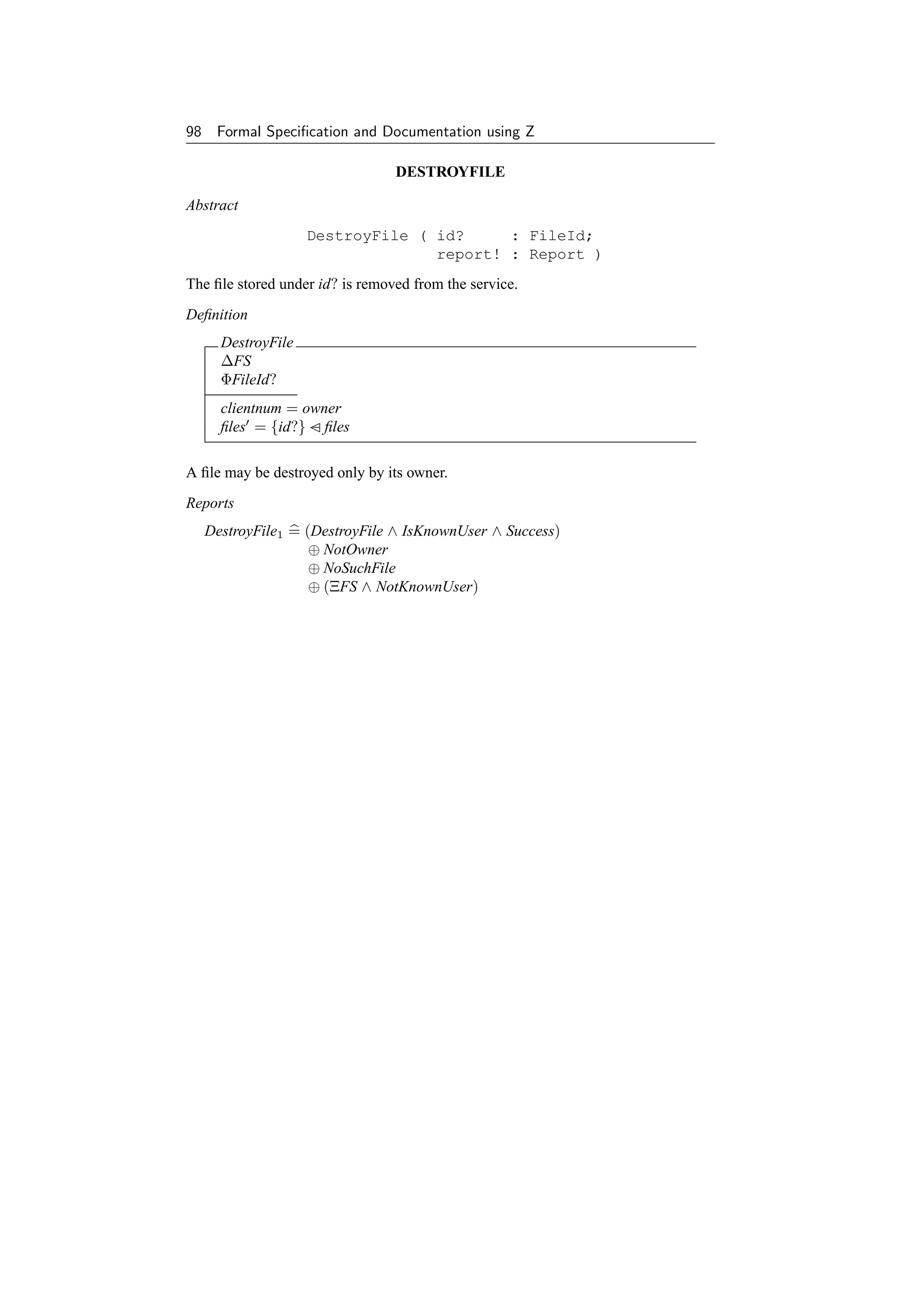
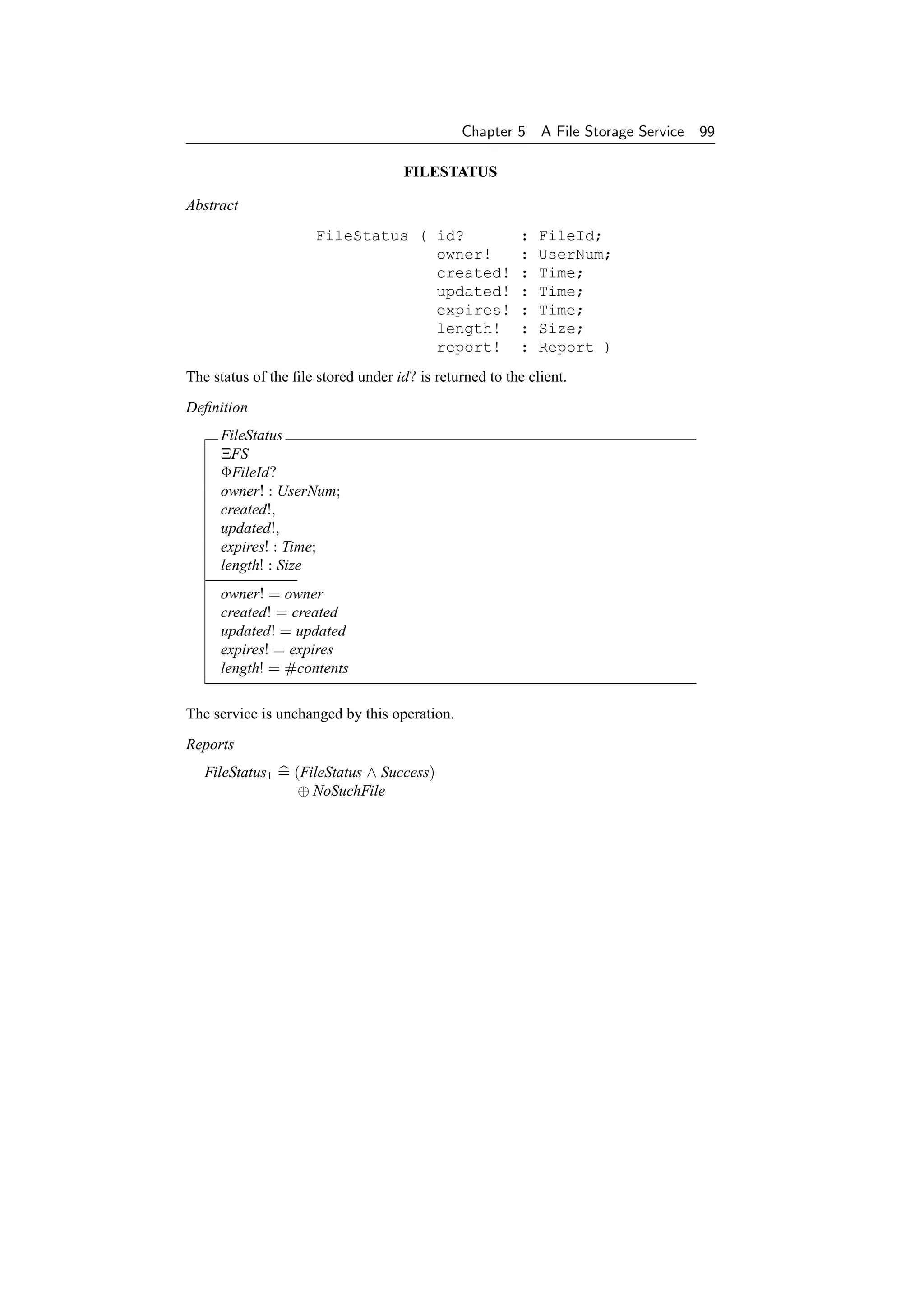
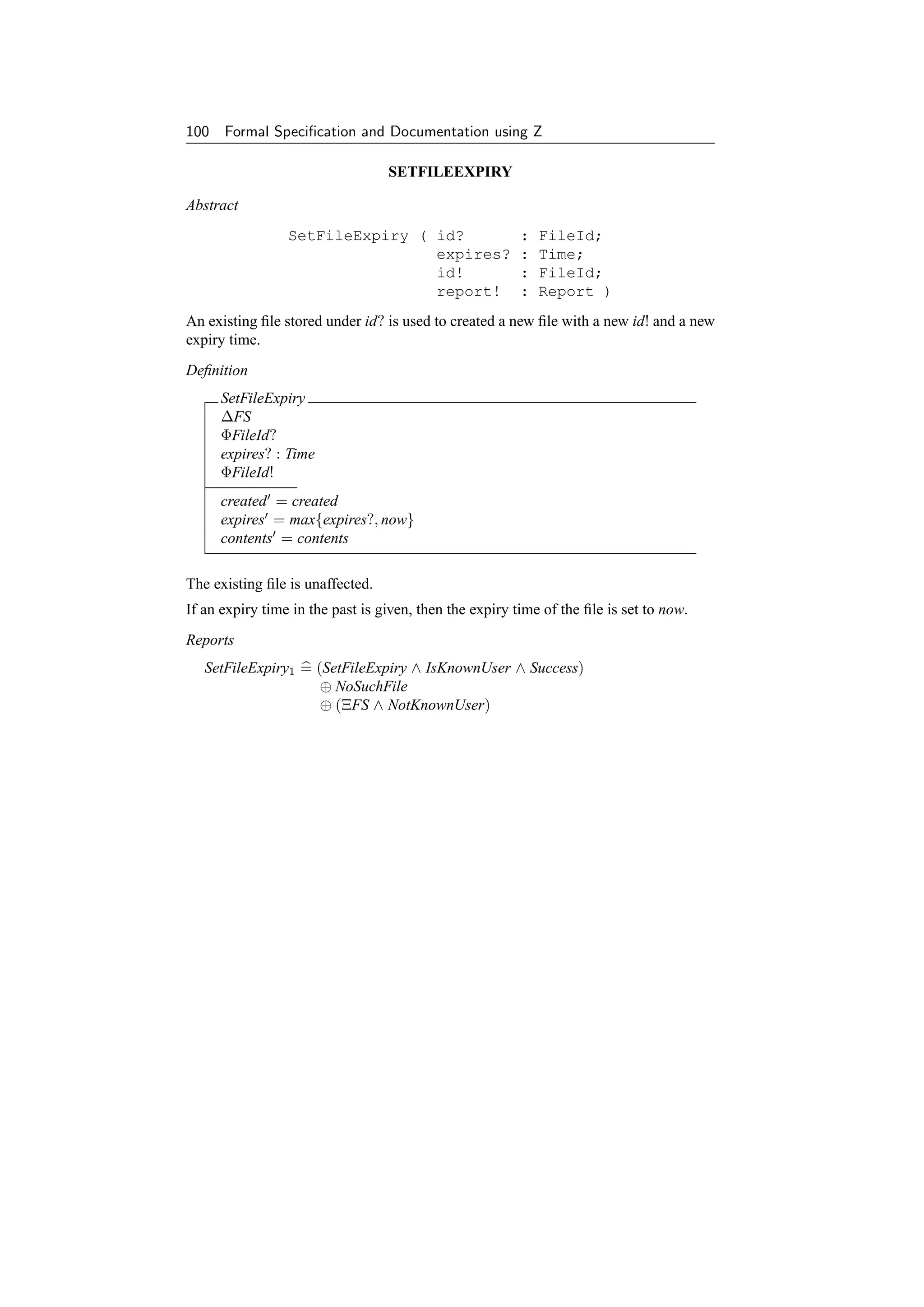

![102 Formal Specification and Documentation using Z
5.3.2 Manager operations
There is a service manager who has several special operations available to help with
the running of the service:
Enable – enable file storage service.
Disable – disable file storage service.
These are described in the Common Service Framework document [55].
5.3.3 Implementation operations
Some operations are needed because of the implementation of the file storage service.
For example, there is a scavenge operation which the service may perform at any time:
it cannot, however, be requested by clients.
SCAVENGEFILE
ScavengeFile – remove an expired file.
Abstract
ScavengeFile ( id? : FileId )
The file stored under id? is removed from the service; only expired files may be scav-
enged.
A scavenge may be invoked by the file service at any time; it can never be invoked by
clients.
FileService : UserNum
Definition
ScavengeFile
ΦFileId?
clientnum = FileService
expires now
files = {id?} − files
5.4 Costs and Accounting
Costs Every operation which can be performed by a client costs a certain amount
of money, which may have two components. One is the overhead of performing the
operation itself:
NewFileCost,
WriteFileCost,
ReadFileCost,
DestroyFileCost,
FileStatusCost,
SetFileExpiryCost,
SetFileLengthCost : Money](https://image.slidesharecdn.com/zbook-130114070646-phpapp01/75/Zbook-115-2048.jpg)
![Chapter 5 A File Storage Service 103
If an error occurs, a small cost will still be charged:
FSErrorCost : Money
The other component, if present, is related to the service requested by the operation.
For example, the WriteFile operation charges in advance for the storage of the data
submitted, and the DestroyFile operation may give a rebate (negative expense) if the
file is destroyed before its expiry time.
The expense of storing data in a file is determined by applying a tariff function using
the file’s update and expiry times. Similar tariff functions apply to reading data and
obtaining file identifiers. There are various constants involved with this.
StoreByteCost,
ReadByteCost,
GetIdCost : Money
The tariff schema in Figure 5.1 defines the costs involved when a client performs file
storage service operations. These are described using the constants introduced above
and the scheme outlined in the Common Service Framework document [55].
5.4.1 Accounting policy
The values of NewFileCost, etc., and of the tariff functions may be varied; their precise
values at any time will be published separately. Expenditure will be recorded in a log,
and clients will be expected to observe any limits placed upon them.
5.5 Total Operations
This section provides a full definition of all the total operations which clients may
request the file storage service to perform. This definition uses schemas which are
defined in this document as well as those which check authentication etc., as defined
in the Common Service Framework document [55].
ΦOp = [op? : Op]
NewFileOp, WriteFileOp, ReadFileOp, DestroyFileOp,
FileStatusOp, SetFileExpiryOp, SetFileLengthOp : Op
NewFileOp, WriteFileOp, ReadFileOp, DestroyFileOp,
FileStatusOp, SetFileExpiryOp, SetFileLengthOp ∈ iseq Op
The set of operations implemented by the file storage service for clients is given in
Figure 5.2.
5.6 Security
The service provides limited security in two areas; in both cases it depends on certain
values being chosen from such a large set that they are hard to guess.
A client may not access a file unless he knows its id, and file ids are hard to guess.
The identifier of any file is initially known only to its creator; the service will never
tell any client the identifier of a file he does not own.](https://image.slidesharecdn.com/zbook-130114070646-phpapp01/75/Zbook-116-2048.jpg)
![104 Formal Specification and Documentation using Z
Tariff
∆FS
op? : Op
ΦFileId?
ΦFileId!
data! : Data
idset! : F FileId
cost! : Money
report! = SuccessReport ⇒
op? = NewFileOp ⇒ cost! = NewFileCost
op? = WriteFileOp ⇒ cost! = WriteFileCost
+ StoreByteCost ∗ (expires − updated ) ∗ #contents
op? = ReadFileOp ⇒ cost! = ReadFileCost + ReadByteCost ∗ #data!
op? = DestroyFileOp ⇒ cost! = DestroyFileCost
− StoreByteCost ∗ (expires − updated ) ∗ #contents
op? = FileStatusOp ⇒ cost! = FileStatusCost
op? = SetFileExpiryOp ⇒ cost! = SetFileExpiryCost
+ StoreByteCost ∗ (expires − expires) ∗ #contents
op? = SetFileLengthOp ⇒ cost! = SetFileLengthCost
+ StoreByteCost ∗ (expires − updated )
∗ (#contents − #contents)
report! ∈ {NoSuchFileReport, NoSpaceReport, NotOwnerReport,
NotKnownUserReport} ⇒ cost! = FSErrorCost
Figure 5.1 File Storage Service tarriff schema.
Ops = Tariff ∧ ((ΞFS ∧ BadOperation) ⊕
([NewFile1 ; ΦOp | op? = NewFileOp] ∨
[WriteFile1 ; ΦOp | op? = WriteFileOp] ∨
[ReadFile1 ; ΦOp | op? = ReadFileOp] ∨
[DestroyFile1 ; ΦOp | op? = DestroyFileOp] ∨
[FileStatus1 ; ΦOp | op? = FileStatusOp] ∨
[SetFileExpiry1 ; ΦOp | op? = SetFileExpiryOp] ∨
[SetFileLength1 ; ΦOp | op? = SetFileLengthOp]))
Figure 5.2 Combined file system operations.](https://image.slidesharecdn.com/zbook-130114070646-phpapp01/75/Zbook-117-2048.jpg)


![Chapter 6
A Text Formatting Tool
In this chapter a simple text processing tool which allows left, centred and right
justification of lines within an ASCII text file is formalized in Z. Implementation
details such as the use of tab characters and newline sequences are covered. The
program has been implemented under the widely used UNIX operating system [37].
Readers may like to peruse the UNIX manual page for the tool, reproduced on
page 118, before reading the chapter.
6.1 Basic Concepts
The UNIX filing system has been specified in Z elsewhere (see [298]). Here we con-
sider individual UNIX text files which consist of ASCII characters. We denote the set
of characters under consideration as CHAR.
[ CHAR ]
One of these characters is a blank space.
space : CHAR
Characters are organized as lines in a text file. A complete text file, or document,
consists of a number of lines of characters.
LINE == seq CHAR
DOC == seq LINE
We have modelled a line as a sequence of characters and a document as a sequence
of lines above. Suppose a sequence needs to be repeated a certain number of times.
The Z specification language may be extended, as done in its mathematical ‘toolkit’
for many operators, by defining a generic function to do this.
[X]
: (seq X) × N → seq X
∀ s : seq X; n : N1 •
s0 = ∧
sn = s (s(n − 1))
109](https://image.slidesharecdn.com/zbook-130114070646-phpapp01/75/Zbook-122-2048.jpg)


![Chapter 6 A Text Formatting Tool 113
[X]
split : (seq X) × N1 → seq(seq X)
∀ s : seq1 X; n : N1 ; ss : seq1 (seq1 X) •
split n = ∧
s split n = ss ⇔
/ ss = s ∧
(∀ t : seq X | t ∈ ran(front ss) • #t = n) ∧
0 #(last ss) ≤ n
The trailing spaces of a line segment can be converted to a tab if the line segment
has the length of the distance between tab column positions. There should also be
more than one trailing space since this will reduce the length of the line and make the
substitution using a tab character worthwhile.
addtab : LINE → LINE
∀ l : LINE | tab ∈ ran l •
/
(#l = tabsize ∧ #(clipright l) #l − 1) ⇒
addtab l = (clipright l) tab ∧
(#l = tabsize ∨ #(clipright l) ≥ #l − 1) ⇒
addtab l = l
These functions may be combined together to convert spaces in a line to tabs where
appropriate:
unexpand : LINE → LINE
∀ l : LINE | tab ∈ ran l •
/
unexpand l = /((l split tabsize) o addtab)
9
This function should only be applied to lines not containing tabs and in this case
always reduces the length of the line, or leaves it the same.
∀ l : LINE | tab ∈ ran l • #(unexpand l) ≤ #l
/
Now consider a function to cut a sequence into a series of segments after each occur-
rence of a non-empty pattern.
[X]
cut : (seq X) × (seq1 X) → seq(seq X)
∀ p : seq1 X; s, t : seq X | ¬ (p ⊆ front(s p)) •
cut p = ∧
s= ⇒ s cut p = s ∧
(s p t) cut p = s p (t cut p)
Note that combining these segments back together again results in the original se-
quence:](https://image.slidesharecdn.com/zbook-130114070646-phpapp01/75/Zbook-126-2048.jpg)
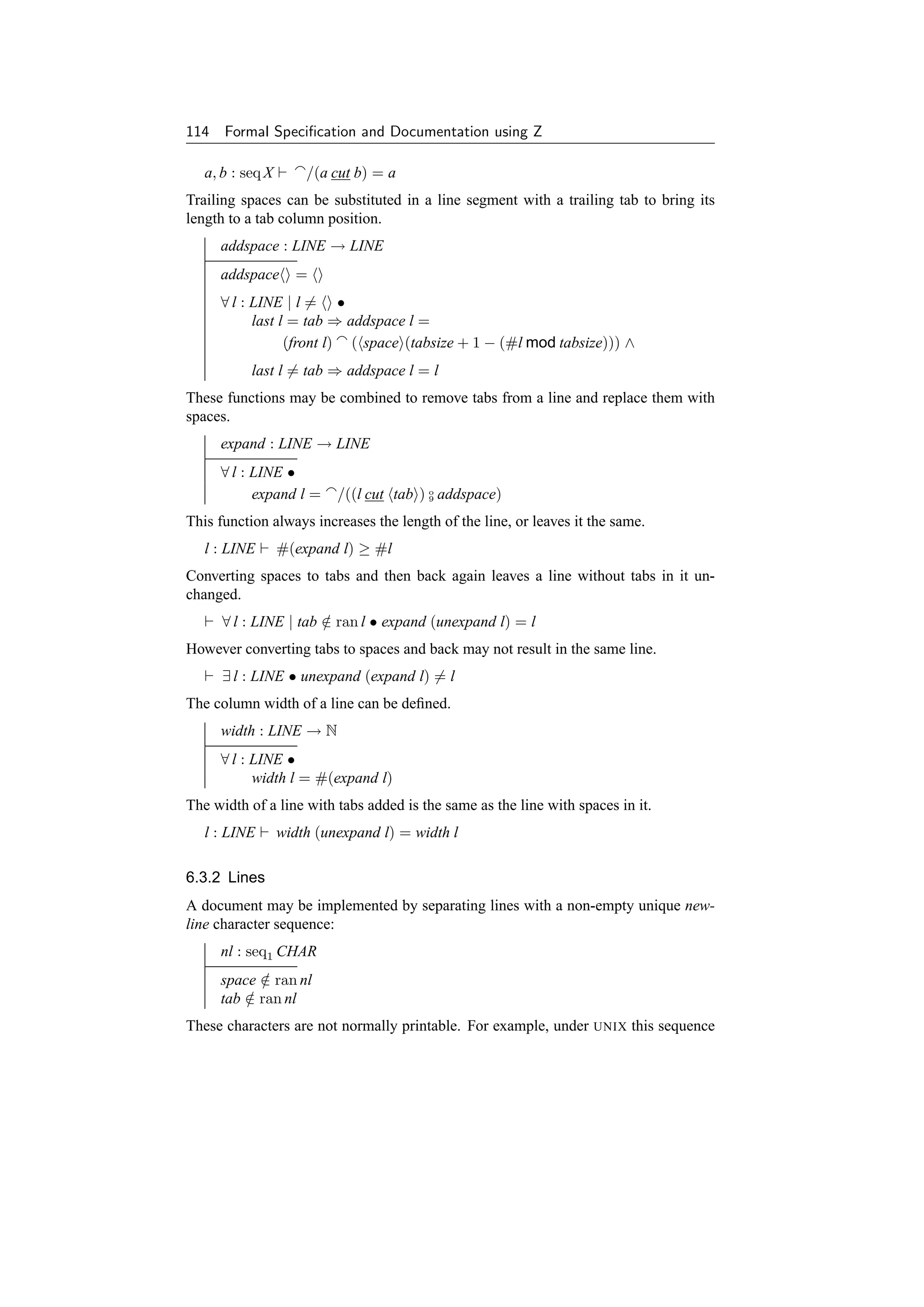
![Chapter 6 A Text Formatting Tool 115
normally consists of the ASCII line-feed ‘control’ character. Under some other op-
erating systems it can consist of a combination of the carriage return and line-feed
characters. The characters should not occur within any line.
Consider a function which combines a sequence of segments using another se-
quence as a terminator for each of the segments.
[X]
comb : (seq(seq X)) × (seq X) → seq X
∀ s, p : seq X; ss : seq(seq X) •
comb p = ∧
s comb p = s p∧
(s ss) comb p = s p (ss comb p)
By using a terminator rather than a separator the empty sequence (e.g., an empty
document) and a sequence containing the empty sequence (e.g. a document containing
a single empty line) may be differentiated.
p : seq X comb p =
p : seq X comb p = p
Conversely, consider a function to separate a sequence into a series of segments using
a non-empty pattern.
[X]
sep : (seq X) × (seq1 X) → seq(seq X)
∀ s : seq X; p : seq1 X; ss : seq(seq X) •
s sep p = ss ⇔
ss comb p = s ∧
( ∀ t : seq X | t ∈ ran ss • ¬ (p ⊆ t) )
Note that the sequence to be separated must be terminated with the pattern or be empty
to be valid.
6.4 Files
A UNIX file is implemented as a sequence of characters [298], possibly containing tab
characters and newline sequences.
FILE == seq CHAR
On input, a number of such files are to be converted into a single document without
tab characters or newline sequences.](https://image.slidesharecdn.com/zbook-130114070646-phpapp01/75/Zbook-128-2048.jpg)
![116 Formal Specification and Documentation using Z
PrePOS0
TEXT
input? : seq FILE
text = (( / input?) sep nl) o expand
9
On output, a single document is produced. Blanks may optionally be converted to tabs
when this reduces the size of the document.
Blanks ::= Yes | No
PostPOS0
blanks? : Blanks
output! : FILE
TEXT
blanks? = Yes ⇒ output! = text comb nl
blanks? = No ⇒ output! = (text o
9 unexpand) comb nl
These schemas may be combined to produce a new specification for the behaviour of
an implementation of the tool under UNIX.
POS = PrePOS0 ∧ POS0 ∧ PostPOS0
6.5 Conclusion
This specification is based on a simple text processing tool which was written in the
programming language C [244] for use under the UNIX operating system. There are
some differences, but these and the manual page for this tool are included on page 118
for comparison.
Of course, normally a formal specification should be written before an implemen-
tation is produced. In this case this was not so because the author was not enlightened
when he wrote the original program some years ago. However there are still bene-
fits in producing a post hoc specification. This can be useful if a product is to be
re-engineered [319]. It can also help in improving the documentation of an existing
system [41, 80].
This chapter shows that text processing concepts may be documented using a for-
mal notation. By formalizing a system, ambiguity and misunderstanding are reduced.
Additionally, reasoning about the properties of the system becomes easier and can be
done with more confidence. Software developed from formal specifications is likely
to contain less errors. Studies on industrially sized examples of software development
have confirmed this view [247]. For these reasons, it is hoped that formal specifica-
tion will become more widely used in the field of practical software engineering in the
future.
The specification was previous published as an article [44]; it is included by kind
permission of the Institution of Electrical Engineers (IEE), UK.](https://image.slidesharecdn.com/zbook-130114070646-phpapp01/75/Zbook-129-2048.jpg)

![118 Formal Specification and Documentation using Z
POS(1) UNIX Manual POS(1)
NAME
pos – simple text column positioning
SYNOPSIS
pos [ –b ] [ column ] [ file ... ]
DESCRIPTION
Pos is a simple text formatter which reads the concatenation of input files (or stan-
dard input if none are given) and produces on standard output a version of its input
with lines positioned according to the column parameter. Column is a number
specifying a column position starting from column 1. If it is unsigned then text is
centered about that position. If it is negative, -column then the left hand margin
of the text is positioned at the specified column. If it is signed positive, +column
then the right hand margin of the text is positioned at that column. If the column
parameter is ‘–’, ‘+’ or ‘0’ then the positioning is calculated from the first line in
each file. The default value for column is 40.
All tabs are converted to spaces, although tabs are used for leading space where
appropriate unless the –b option is used in which case only spaces are used on
output. Interword spacing on each line is preserved. If a line is too long then it is
simply outputted with its leading white spaces removed so that no non-blank text
is lost. Lines starting with a ‘.’ are not formatted but are simply outputted as read.
Pos is meant to format headings and other short pieces of text. For instance, within
visual mode of the ex editor (e.g., vi) the command
!}pos
will center a paragraph.
AUTHOR
Jonathan Bowen, Oxford University
SEE ALSO
colrm(1), expand(1), fmt(1), nroff(1)
BUGS
The program is designed to be simple and fast – for more complex operations, the
standard text processors are likely to be more appropriate. Control characters other
than tabs will confuse pos.](https://image.slidesharecdn.com/zbook-130114070646-phpapp01/75/Zbook-131-2048.jpg)
![Chapter 7
An Event-based Input
System
In this chapter a design is given for an event-based input system for use on graphics
workstations that overcomes problems associated with some earlier designs. An
interface is specified which allows a client to select events to be queued from the set
of those available, get events from the input queue, put events in the input queue,
flush the input queue, and connect a set of polled events to a queued event. The
system has been designed with the intention of being implementable on a number
of systems and has also been formally specified using the Z specification language.
The system has been implemented on UNIX workstations.
7.1 Motivation
Many existing input systems have been based on the design of a particular device or
subsystem and/or have been specialized to the needs of a particular window system.
This has several problems which are discussed in [80]. The event queue system is
independent of any particular application or window system. It provides a set of gen-
eral purpose interfaces and is extensible to accommodate new input devices and event
types. This results in a system that is useful to a diverse range of applications.
The event queue is a system module analogous to the UNIX operating system [37]
tty handler for dealing with the standard ASCII terminal user interface. It provides
a set of procedures and data structures which a physical device driver, or client (user
process) may access. The event queue provides a set of logical devices with fixed
semantics. A given logical device abstracts from the large variety of physical devices
which may possibly implement it. The event queue system was first implemented
under UNIX on a large VAX system (11/785) with a large variety of attached input
devices, and later on MicroVAX II workstations [80].
Several existing systems were considered in the design of the present system. Short-
comings of existing input systems (such as those associated with the X Window Sys-
tem [357, 358, 359]) influenced this design.
In this chapter, Z is used to describe the operation of the system formally. An ab-
stract state of the system is presented, and then the effect of individual library routines
on the state is given. In addition, the corresponding C programming language [244]
declarations are included in italics before the formal description where appropriate to
aid those familiar with the C programming language.
119](https://image.slidesharecdn.com/zbook-130114070646-phpapp01/75/Zbook-132-2048.jpg)
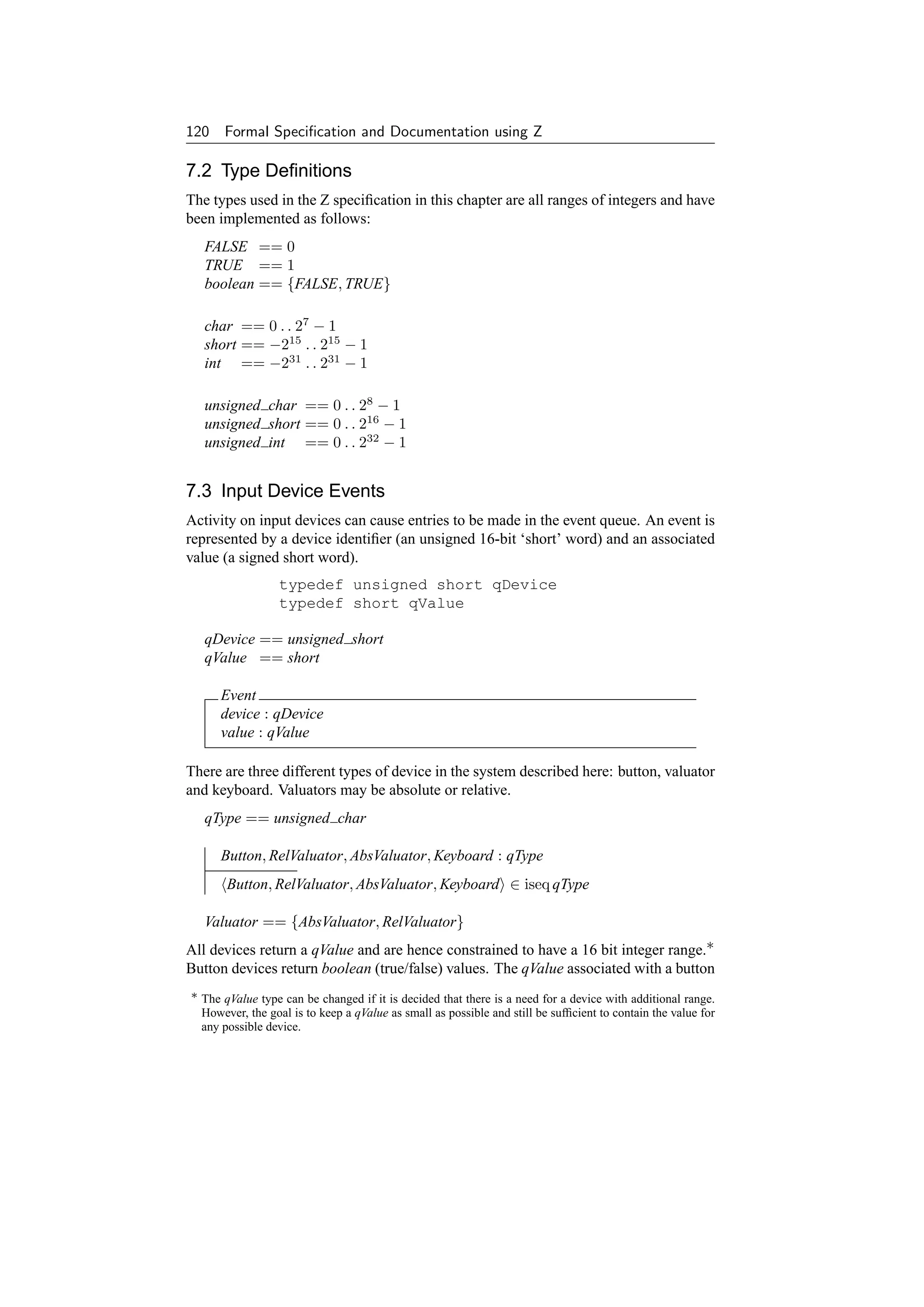

![122 Formal Specification and Documentation using Z
InitState
State
devices = ∅
enabled = ∅
events =
ran bindings = { }
cursor = (0, 0)
∀ dev : qDevice | dev ∈ dom devices •
(devices dev).value = 0 ∧
(devices dev).delta = 0
7.5 Changes of State
Operations change the state of the system. However the device types always remain
the same. They depend on their values at initialization time.
∆State
State
State
dom devices = dom devices
∀ dev : qDevice | dev ∈ dom devices •
(devices dev).type = (devices dev).type
Some operations do not affect the state. (Note that in practice the actual device values
change asynchronously but this does not affect the abstract specification.)
ΞState = [∆State | θState = θState]
For most operations, only a small part of the state is changed. The following schemas
are useful in the definition of subsequent operations, by specifying that all but one of
the state components is unaffected.
ΦDevice = ∆State ∧ ( ΞState (devices) )
ΦEnable = ∆State ∧ ( ΞState (enabled) )
ΦEvent = ∆State ∧ ( ΞState (events) )
ΦBinding = ∆State ∧ ( ΞState (bindings) )
ΦCursor = ∆State ∧ ( ΞState (cursor) )
7.5.1 Asynchronous events
Device values may change asynchronously. Button values can only be 0 and 1. For
valuator devices, the change must be greater than the delta resolution of the device.
Keyboards only return ASCII characters.](https://image.slidesharecdn.com/zbook-130114070646-phpapp01/75/Zbook-135-2048.jpg)

![124 Formal Specification and Documentation using Z
AsyncEvent∗ = AsyncEvent0 ∨ AsyncEvent1 ∨ AsyncEvent2 ∨ . . .
These asynchronous events may be thought of as occurring in sequence with opera-
tions invoked by the client. Each operation can be considered as being atomic.
7.6 System Operations
7.6.1 Device types
Each device has an associated identifier. It is possible to determine the type of the
device with the use of the following requests:
boolean isbutton(device)
qDevice device;
boolean isvaluator(device)
qDevice device;
boolean isrelative(device)
qDevice device;
boolean isabsolute(device)
qDevice device;
boolean iskeyboard(device)
qDevice device;
A partially specified schema may be used to capture the general features of these
operations. Then each operation may be defined in terms of this schema.
ΦIs
ΞState
device? : qDevice
qtype : F qType
is : boolean
(devices device?).type ∈ qtype ⇒ is = TRUE
(devices device?).type ∈ qtype ⇒ is = FALSE
/
IsButton = [ ΦIs[isbutton!/is] | qtype = {Button} ]
IsValuator = [ ΦIs[isvaluator!/is] | qtype = Valuator ]
IsRelative = [ ΦIs[isrelative!/is] | qtype = {RelValuator} ]
IsAbsolute = [ ΦIs[isabsolute!/is] | qtype = {AbsValuator} ]
IsKeyboard = [ ΦIs[iskeyboard!/is] | qtype = {Keyboard} ]
The client will know how to interpret the value associated with an event, based on the
type of device and perhaps the detailed device identifier. The semantics of the value
are device dependent.](https://image.slidesharecdn.com/zbook-130114070646-phpapp01/75/Zbook-137-2048.jpg)

![126 Formal Specification and Documentation using Z
Threshold
ΦDevice
device? : qDevice
delta? : short
Device
Device
θDevice = devices(device?)
type = type
value = value
delta = delta?
devices = devices ⊕ {device? → θDevice }
If the device has been selected for queuing by qdevice() then a change of at least delta
must occur on its associated value before an event will be placed in the queue.†
7.6.4 Reading events
The client obtains the next input event from the event queue with the getevent() re-
quest.
qDevice getevent(pValue)
qValue *pValue;
GetEvent
ΦEvent
pValue! : qValue
getevent! : qDevice
Event
θEvent = head events
pValue! = value
getevent! = device
events = tail events
This operation blocks until an event is available. Hence a number of events may be
necessary beforehand.
GetEvent1 = [AsyncEvent∗ | #events 0] o GetEvent
9
Recall that an input event consists of two values – one identifying the device which
generated the event and one giving the value associated with the device at the time of
the event. getevent() returns the device identifier, and places the value associated with
the device for this event in the location pointed to by pValue. The client’s usage is:
short value;
† This interface only really makes sense for valuator type devices. There is also a problem for devices
which are relative versus absolute as this interface implies that the system knows how to determine what
is a change as opposed to an absolute value from the device.](https://image.slidesharecdn.com/zbook-130114070646-phpapp01/75/Zbook-139-2048.jpg)
![Chapter 7 An Event-based Input System 127
qDevice device;
...
device = getevent(value);
For efficiency we are often interested in reading a number of events in one procedure
invocation. The getevents() request performs this function.
qDevice getevents(count, EventArray)
int count;
struct {
qDevice Device;
qValue Value;
} EventArray[count];
GetEvents
ΦEvent
count? : int
EventArray! : int → Event
getevents! : qDevice
EventArray! = succ o (events for count?)
9
getevents! = (head events).device
events = events after count?
getevents returns the device associated with the first event and returns an array of count
events in EventArray. getevents() does not return until all count requested events have
been returned.
Similarly to getevent(), a number of events may be necessary beforehand.
GetEvents1 =
[AsyncEvent∗ ; count? : int | #events ≥ count?] o GetEvents
9
7.6.5 Posting input events
Events may be ‘posted’ (i.e., placed) at the end of the input queue with the postevent
request.
int postevent(count, pDevice, pValue)
int count;
qDevice *pDevice;
qValue *pValue;](https://image.slidesharecdn.com/zbook-130114070646-phpapp01/75/Zbook-140-2048.jpg)

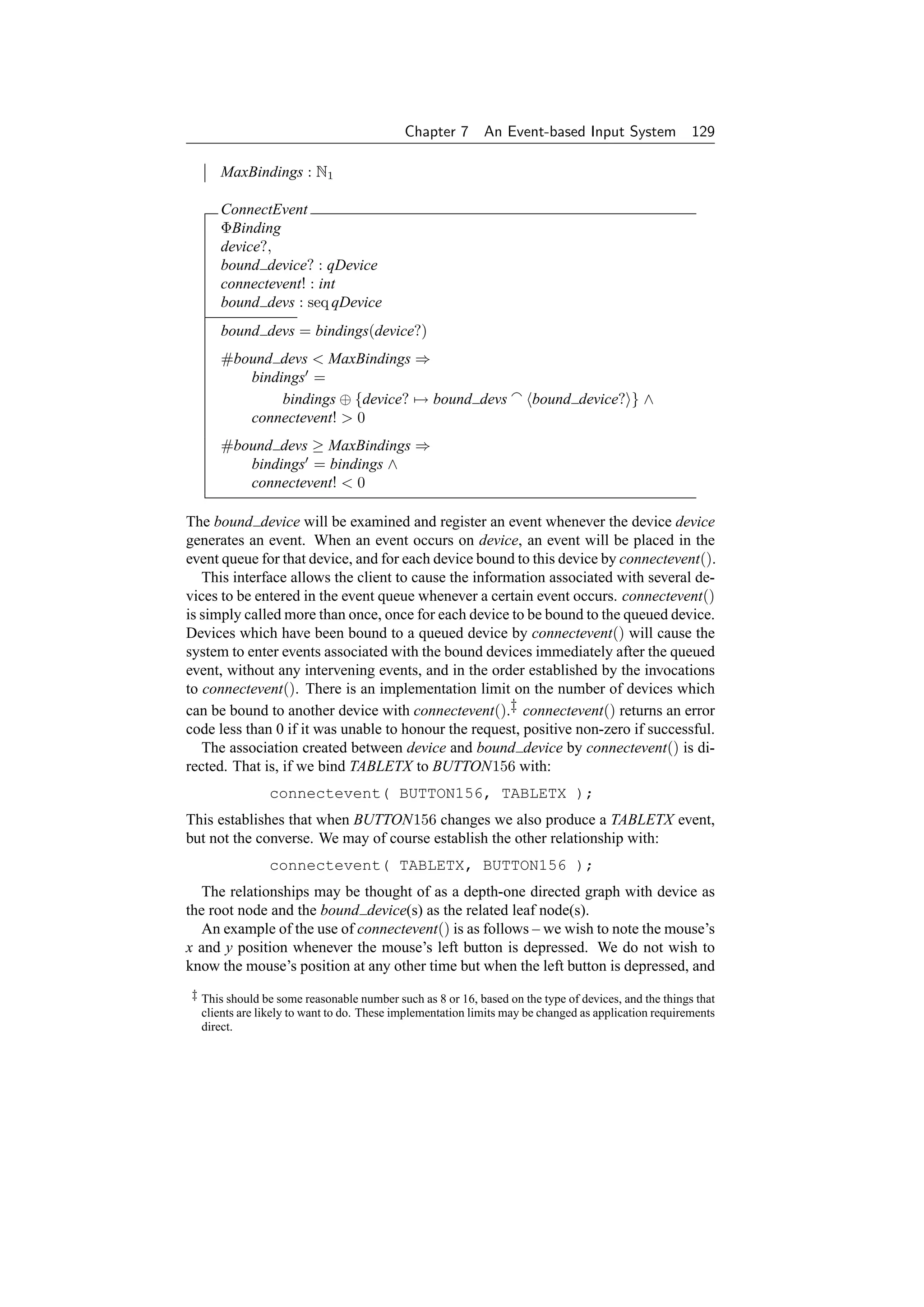
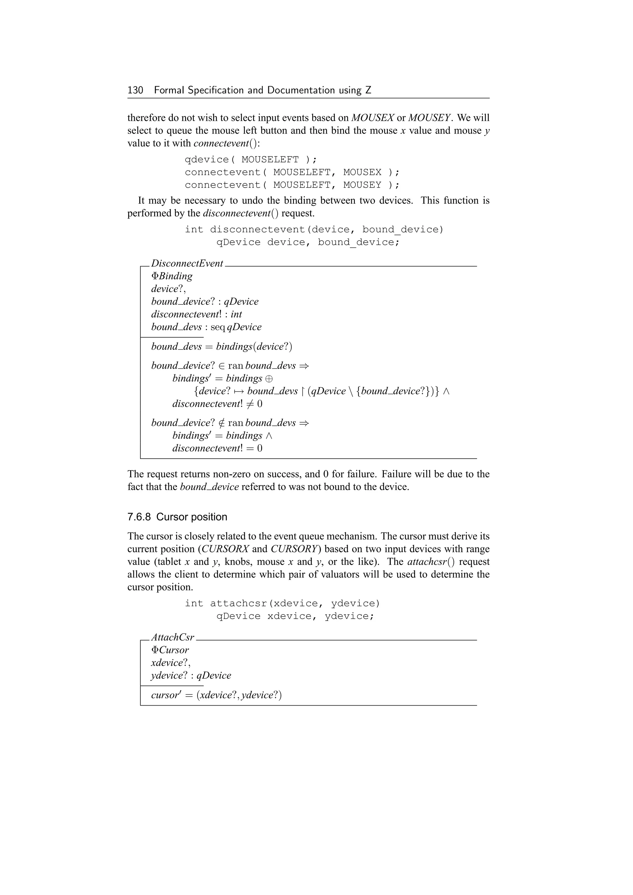


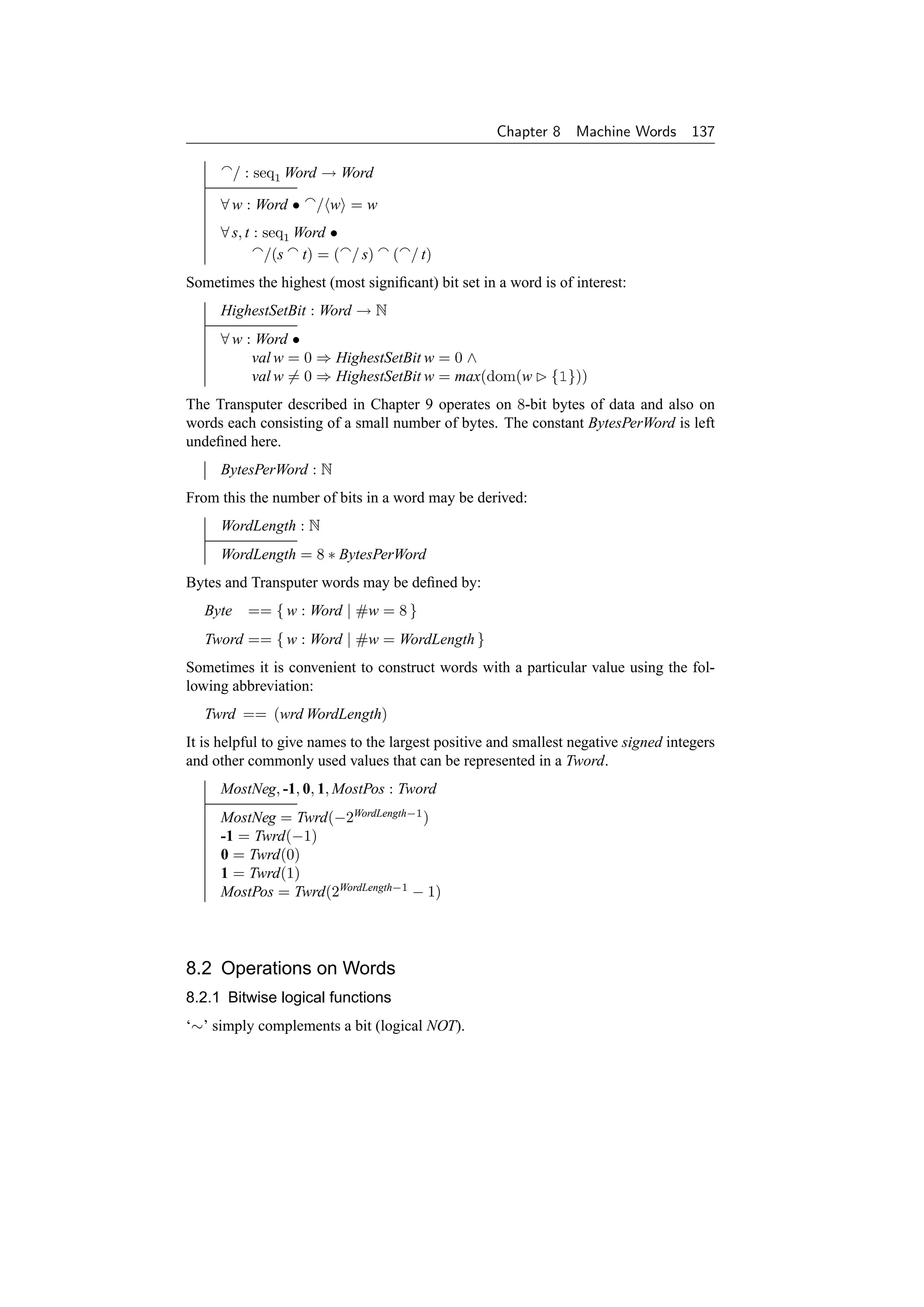
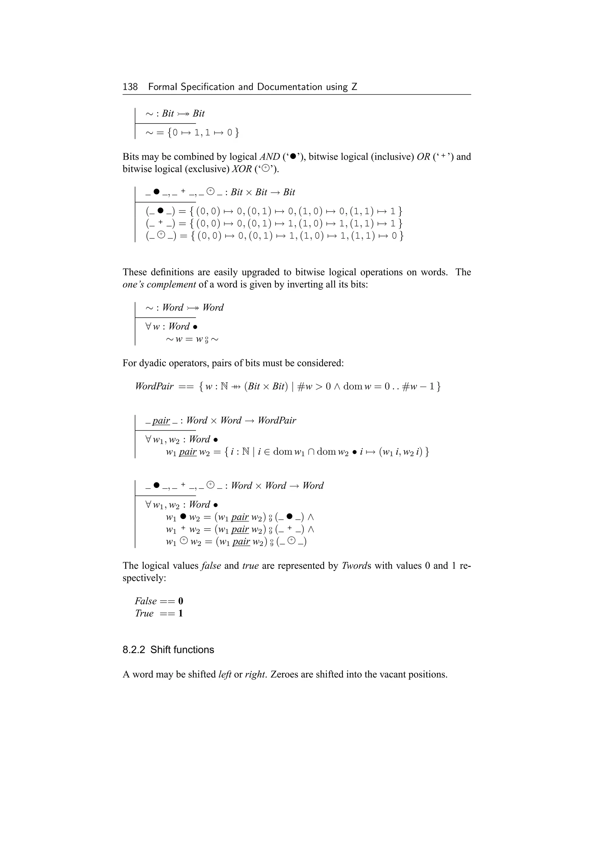
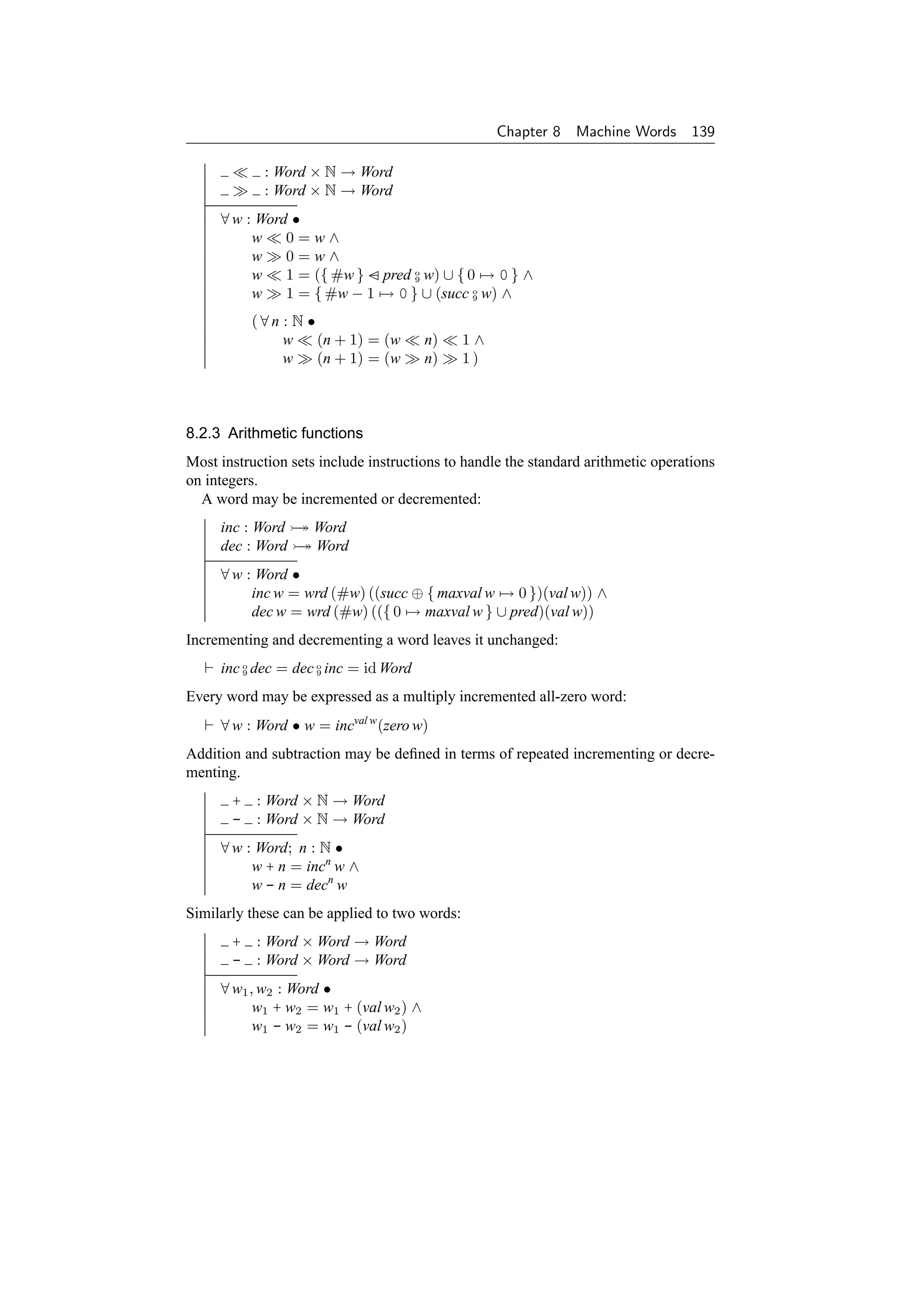

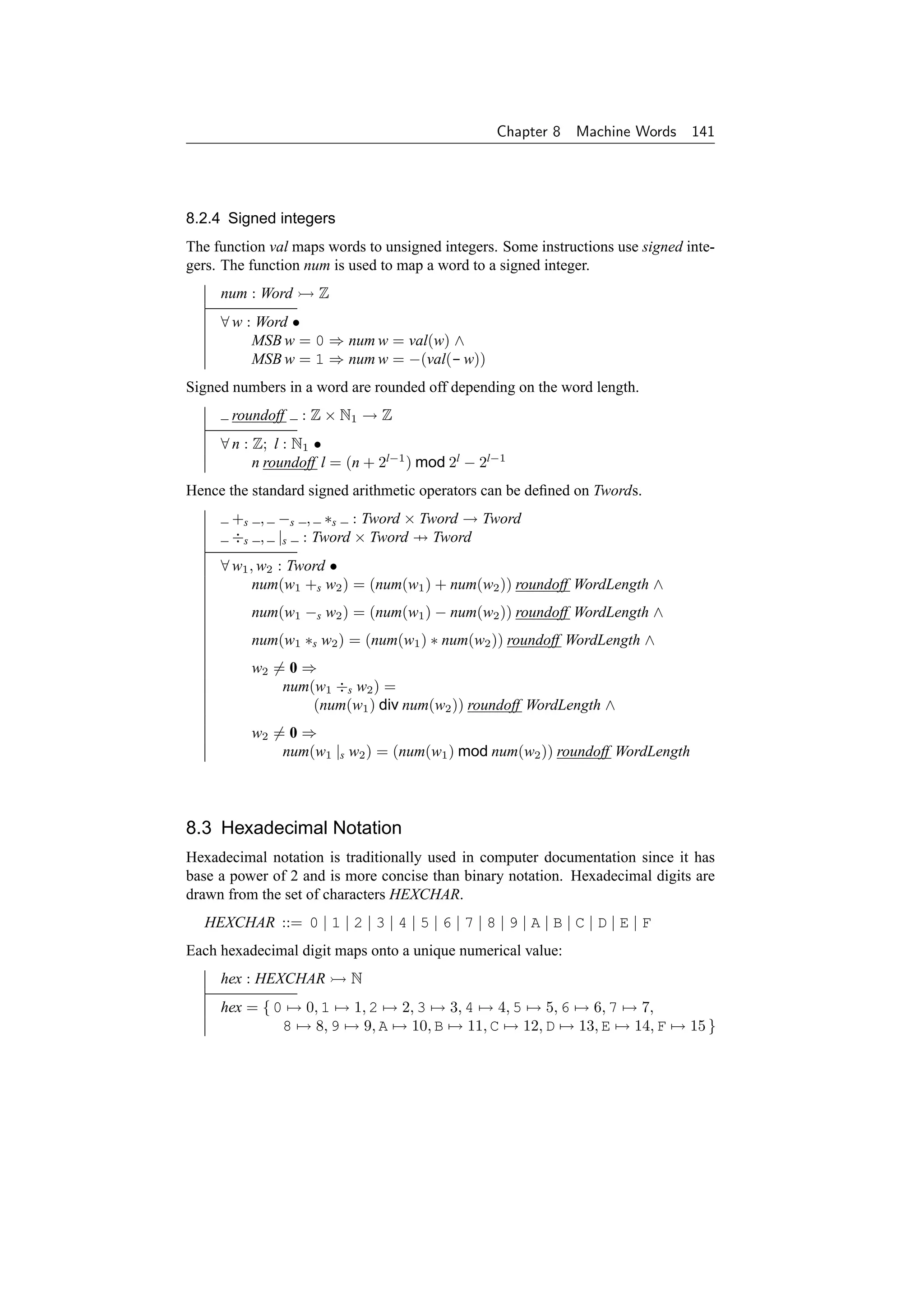

![Chapter 9
The Transputer Instruction
Set
In this chapter, a subset of the Transputer processor instruction set is presented,
building on the basic definitions given in Chapter 8. The Transputer is a com-
mercial microprocessor family developed and marketed by Inmos Limited (now
SGS-Thomson Microelectronics) [224]. This specification is based on a partial
specification of the Transputer instruction set in Z [149]. This itself is based on a
Z specification of the Motorola 6800 microprocessor [38, 39] and a description of
the Transputer instruction set using a Z-like notation produced by Inmos [224].
9.1 Instructions
The following Transputer instructions are covered in this chapter:
• pfix val – prefix value.
• nfix val – negative prefix value.
• ldc con – load constant.
• ldl adr – load local from memory address.
• stl adr – store local to memory address.
• ldlp adr – load local pointer.
• adc con – add constant.
• eqc con – equals constant.
• cj adr – conditional jump to a memory address.
• j adr – unconditional jump to a memory address.
• opr – arithmetic and other operations.
Note that a sequence of pfix and nfix instructions is used to increase the size of
constant or address available to the next instruction. They are not used at the Assembly
Language level.
The opr instruction above performs a number of arithmetic and logical operations,
and also the following operations:
• gt – greater than test.
• rev – reverse registers.
• in – input a message from a channel.
143](https://image.slidesharecdn.com/zbook-130114070646-phpapp01/75/Zbook-156-2048.jpg)

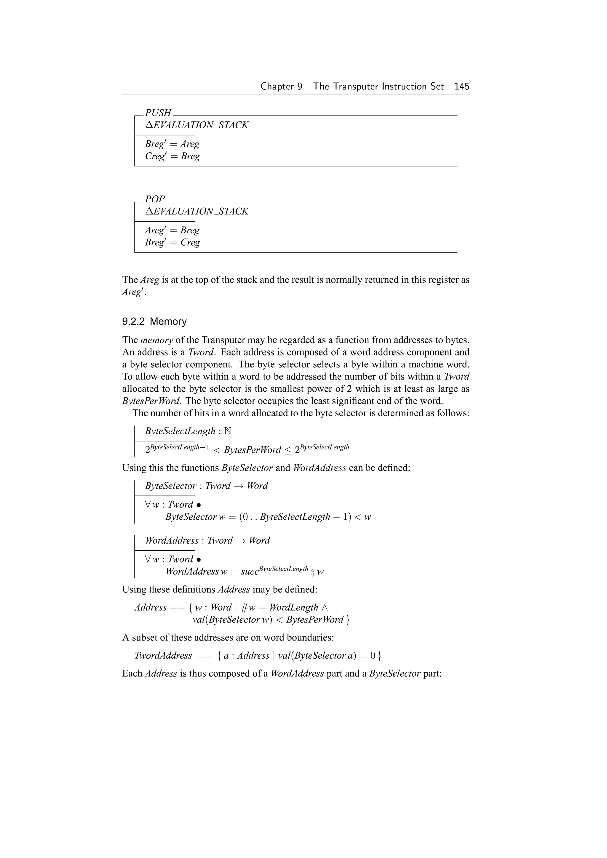
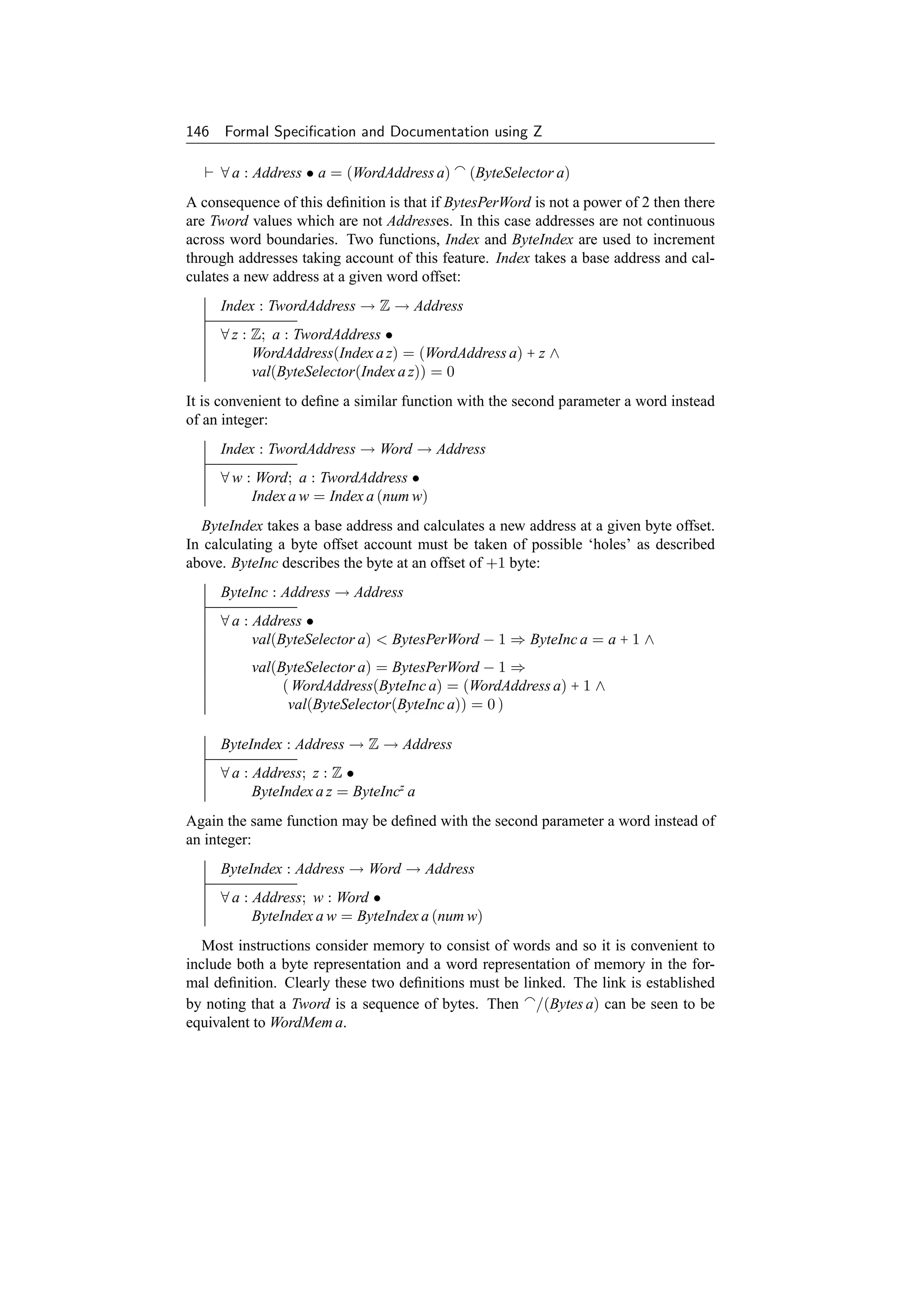
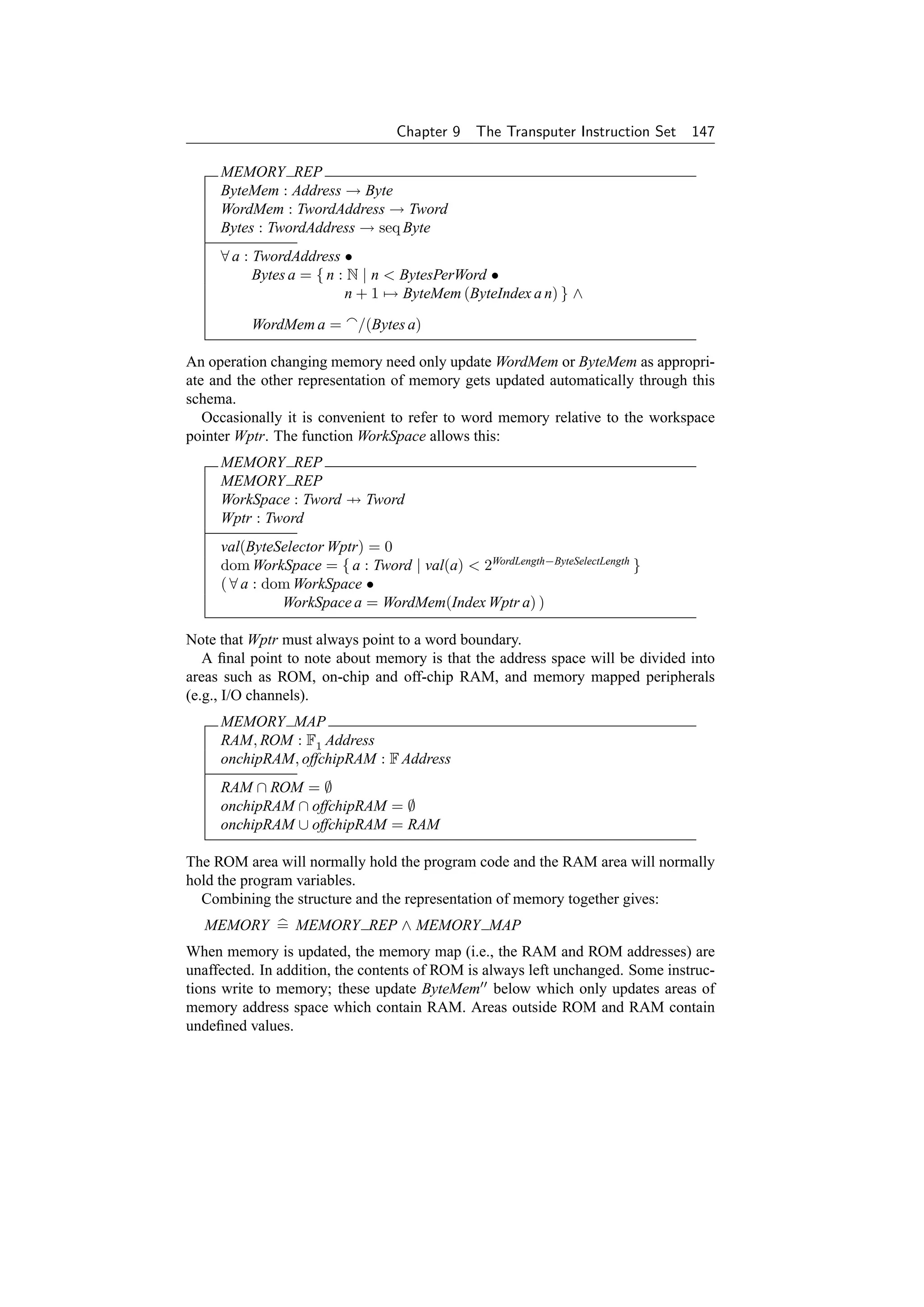
![148 Formal Specification and Documentation using Z
∆MEMORY
MEMORY
MEMORY
ΞMEMORY MAP
MEMORY REP
offchipRAM = offchipRAM
onchipRAM = onchipRAM
ROM ByteMem = ROM ByteMem
RAM ByteMem = RAM ByteMem
Wptr = Wptr
Sometimes the contents of RAM is also left unchanged.
ΞMEMORY =
[ ∆MEMORY | RAM ByteMem = RAM ByteMem ]
9.2.3 System clock
The machine contains a clock which controls the timing of the microprocessor. This
consists of a sequence of pulses and may be modelled by the number of clock pulses
which have occurred since the machine was powered up:
CLOCK
Clk : N
When an instruction is executed it takes a certain number of clock cycles:
∆CLOCK
CLOCK
CLOCK
Cycles : N
Clk = Clk + Cycles
Inclusion of a clock is not strictly necessary in the specification but it allows rea-
soning about the timing of combinations of instructions, should this be desirable in the
future. The clock cycles given for subsequent instructions are taken from [224].
9.2.4 Errors
The Transputer provides a single error flag which may be set by a number of instruc-
tions.
ERROR
ErrorFlag : Bit
The error flag may take the values Clear or Set:
Clear == 0
Set == 1](https://image.slidesharecdn.com/zbook-130114070646-phpapp01/75/Zbook-161-2048.jpg)
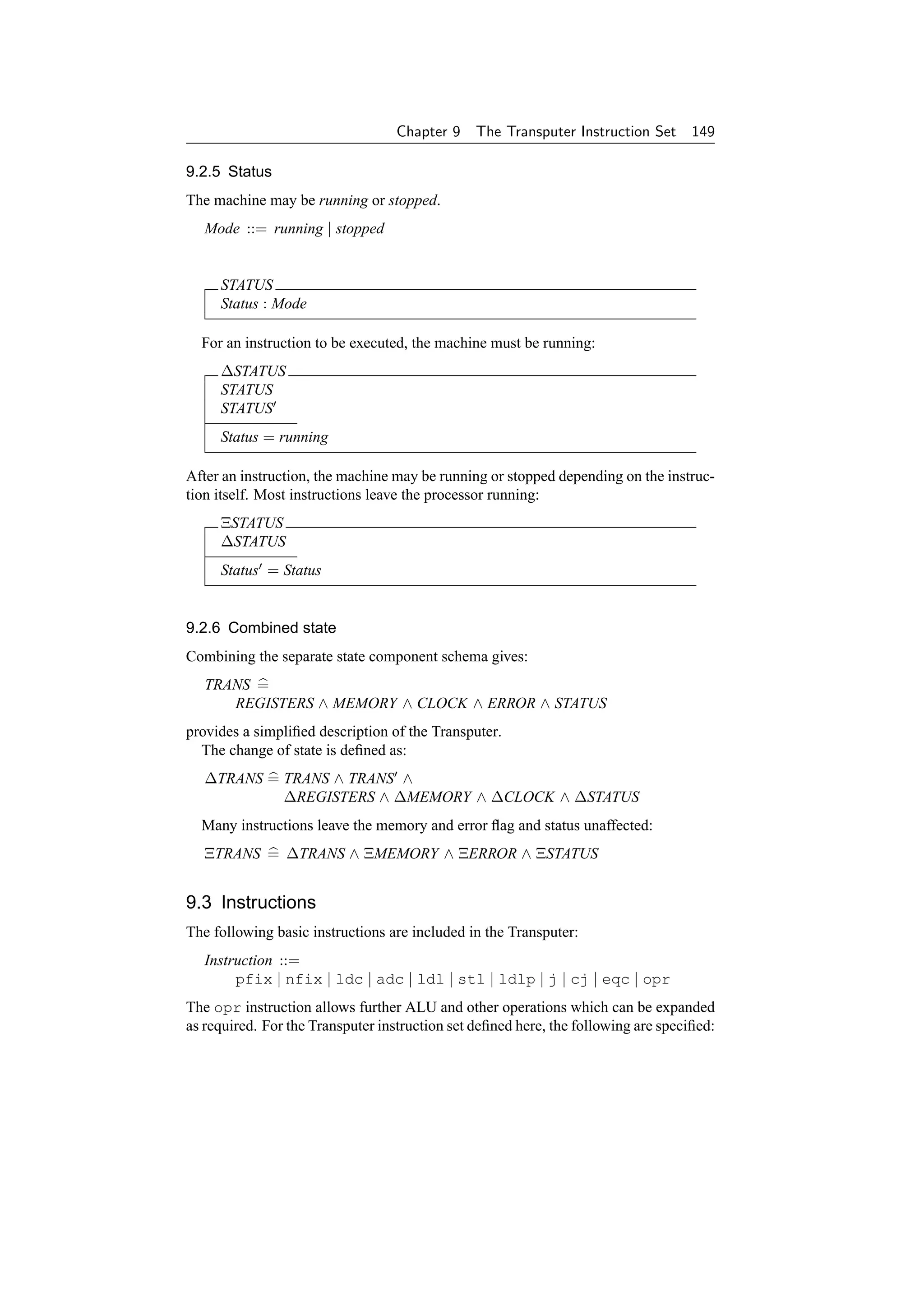
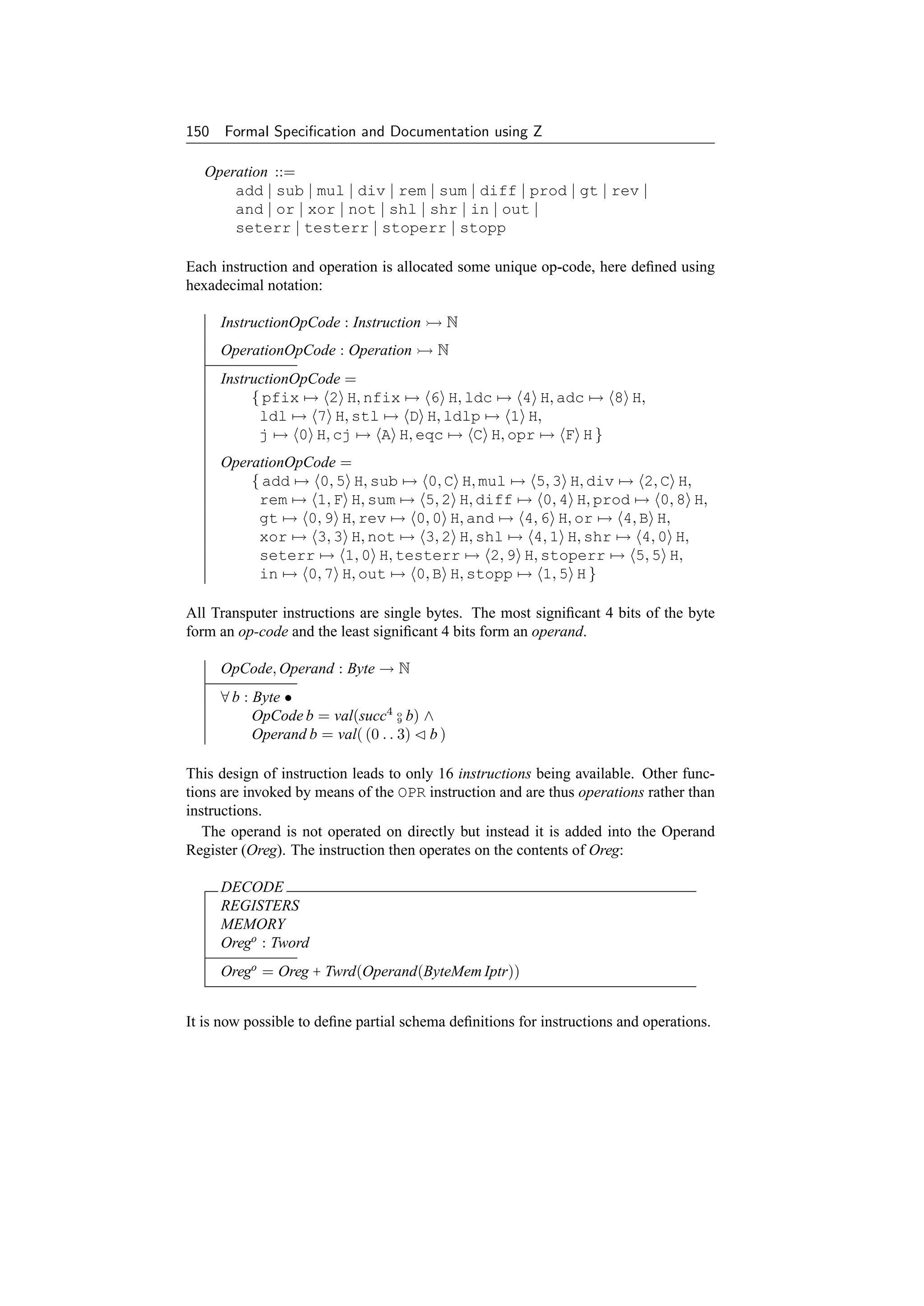
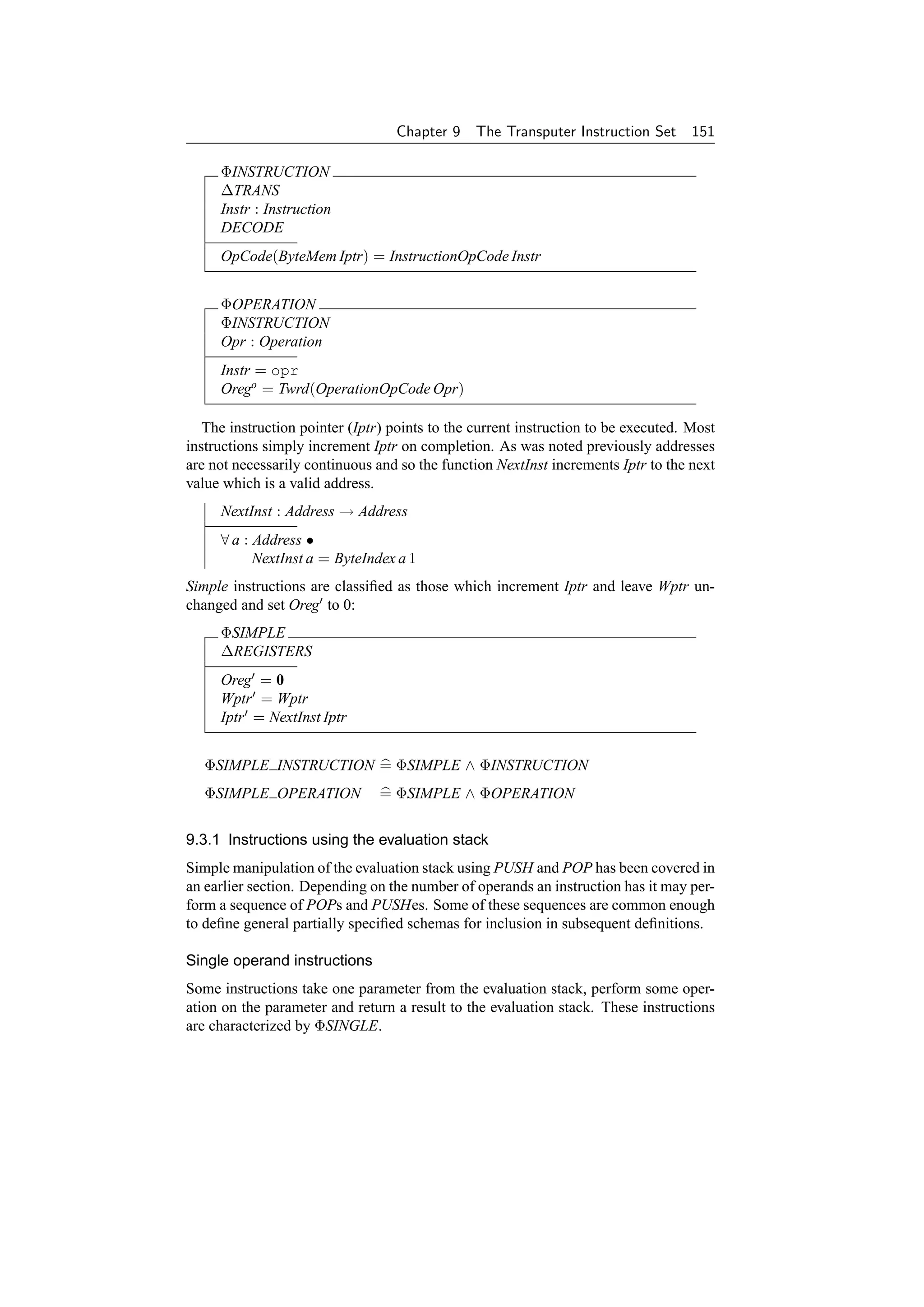

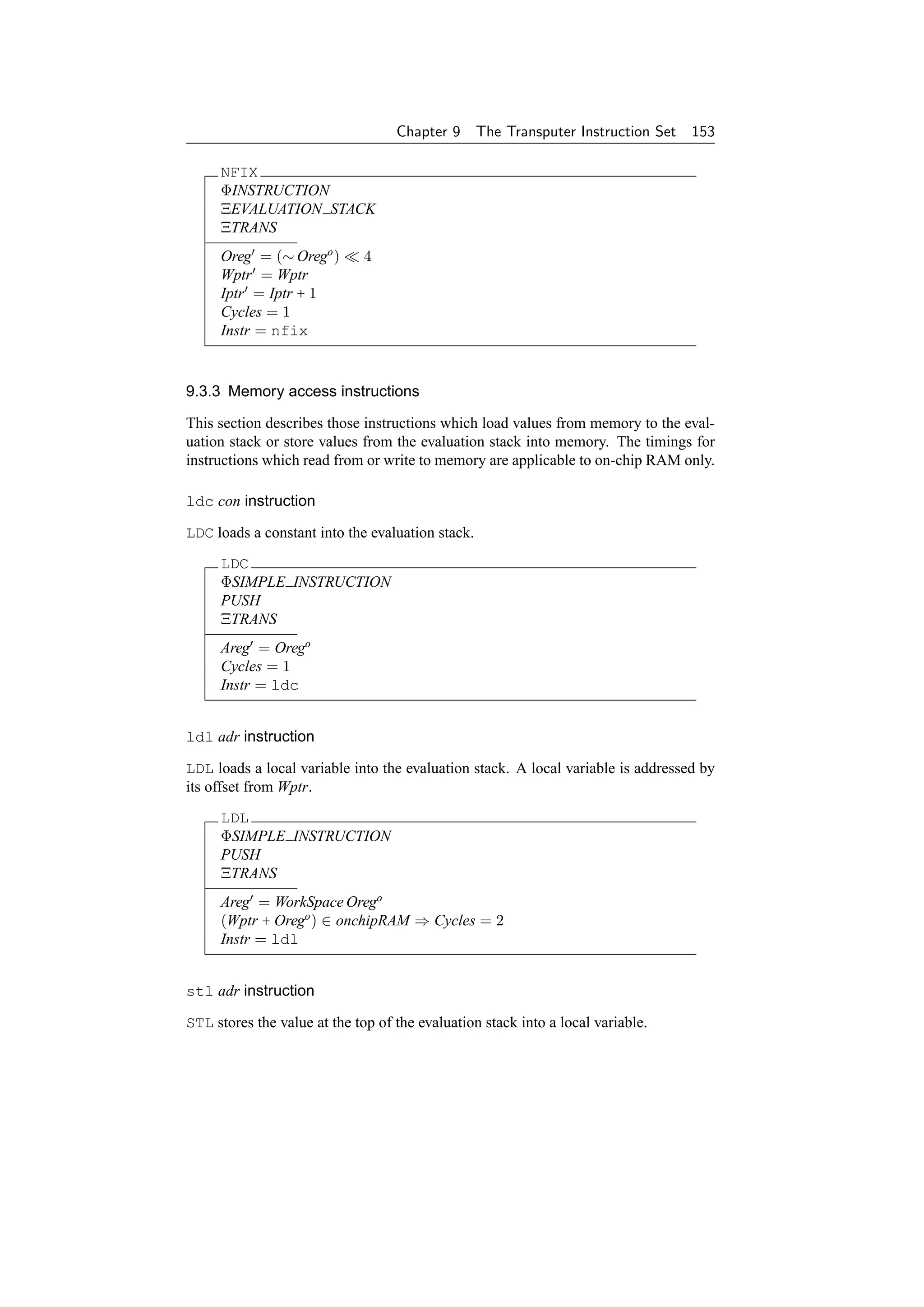
![154 Formal Specification and Documentation using Z
STL
ΦSIMPLE INSTRUCTION
POP
ΞERROR
ΞSTATUS
Orego ∈ dom WorkSpace ⇒
WorkSpace = WorkSpace ⊕ {Orego → Areg }
(Wptr + Orego ) ∈ onchipRAM ⇒ Cycles = 1
Instr = stl
ldlp adr instruction
LDLP loads a local pointer into the evaluation stack.
LDLP
ΦSIMPLE INSTRUCTION
PUSH
ΞTRANS
Areg = Index Wptr Orego
Cycles = 1
Instr = ldlp
9.3.4 Integer arithmetic instructions
Arithmetic operations may lead to overflows. Many of the instructions in this section
check for overflow and set the ErrorFlag if required. Instructions make use of the
dyadic arithmetic operators defined earlier:
dyad[X] == X × X → X
A one-to-one mapping from the arithmetic operators on words is made to the corre-
sponding operators on integers:
ArithOp : dyad[Tword] dyad[Z]
WordOp : P dyad[Tword]
ArithOp = { ( +s ) → ( + ), ( −s ) → ( − ), ( ∗s ) → ( ∗ ) }
WordOp = dom ArithOp
The set of arithmetic word operators is also useful.
InRange checks for arithmetic overflow:
InRange : P(Tword × WordOp × Tword)
∀ w1 , w2 : Tword; op : WordOp •
(w1 , op, w2 ) ∈ InRange ⇔
(ArithOp op)(val w1 , val w2 ) = val( op(w1 , w2 ) )
This is used to set the error flag appropriately after arithmetic instructions.](https://image.slidesharecdn.com/zbook-130114070646-phpapp01/75/Zbook-167-2048.jpg)
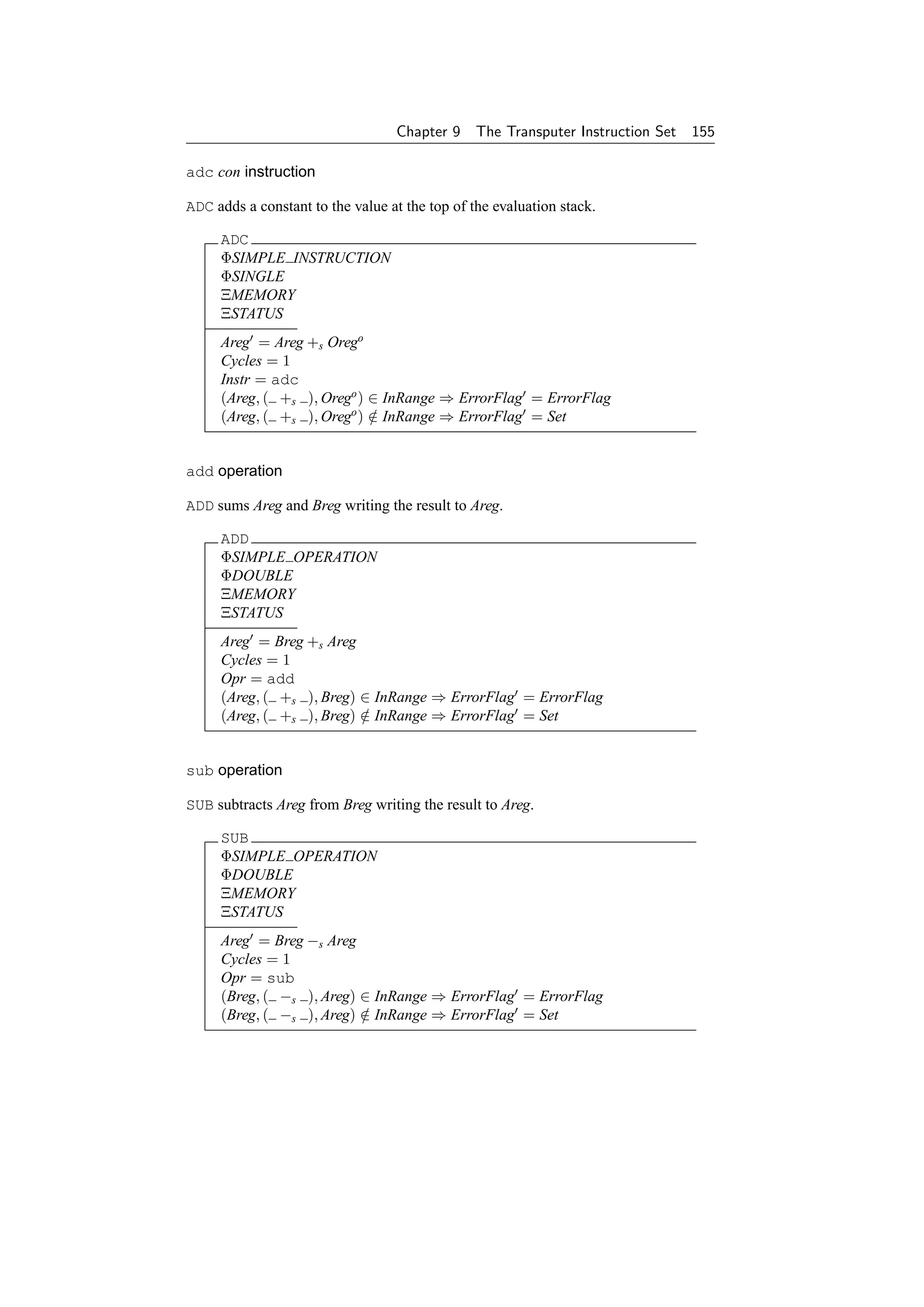


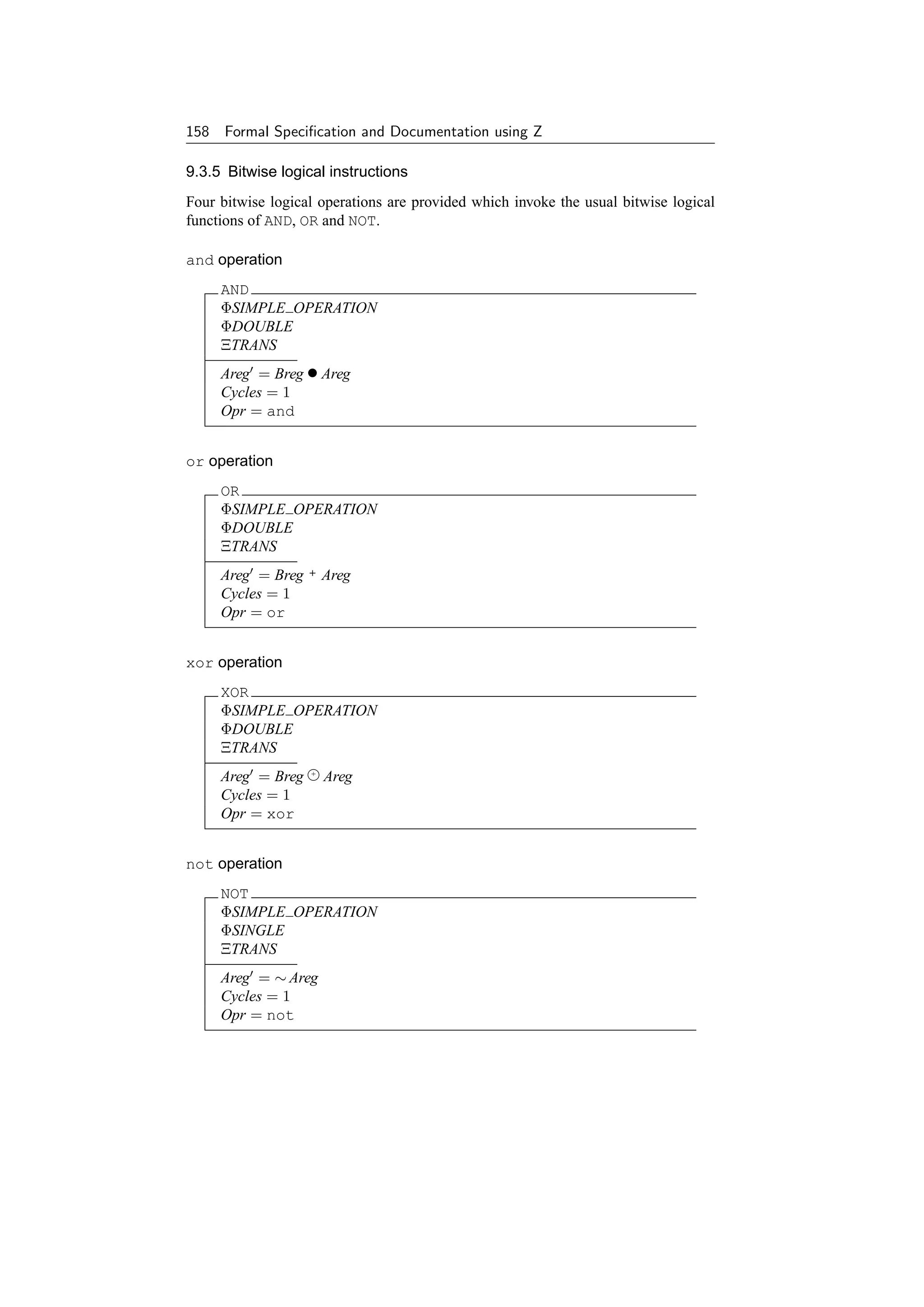

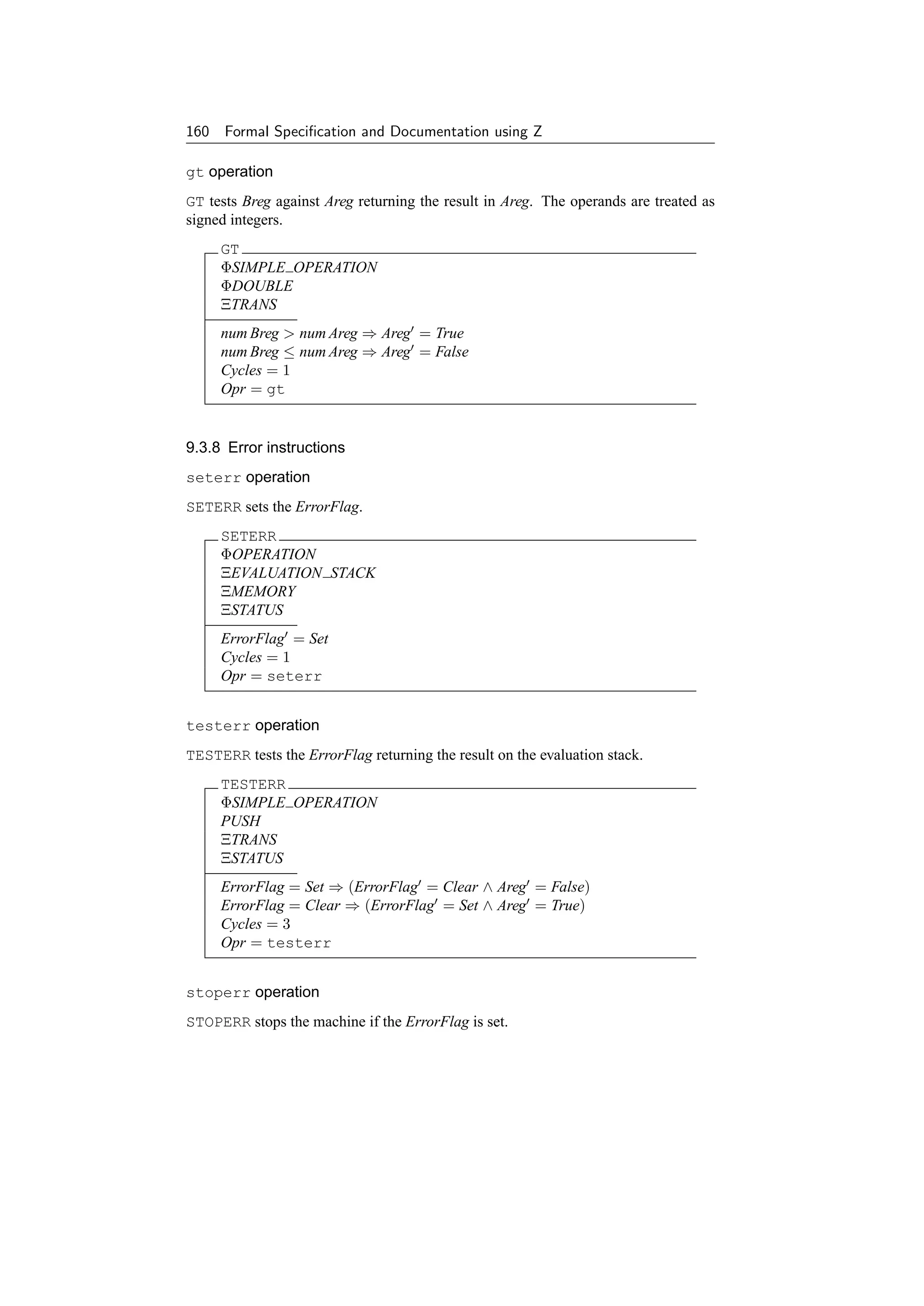

![162 Formal Specification and Documentation using Z
CJ
ΦBRANCH
Areg = 0 ⇒
( ΞEVALUATION STACK ∧ Iptr = JumpAddr ∧ Cycles = 4 )
Areg = 0 ⇒
( POP ∧ Iptr = NextInst Iptr ∧ Cycles = 2 )
Instr = cj
9.3.10 Communication instructions
Communication at the instruction set level is carried out using high level links. The
method of communication is based on CSP [215] and avoids the need for complicated
communications protocols common in other microprocessors. Four hard links are
provided on the Transputer allowing external communication. The links provide two
channels, one in each direction.
InChannels, OutChannels : F TwordAddress
#InChannels = 4
#OutChannels = 4
in instruction
IN reads a sequence of bytes into memory starting at the address specified by Creg.
Areg specifies the length of the sequence. Breg defines the channel address being used.
IN
ΦSIMPLE OPERATION
ΞERROR
ΞSTATUS
Input? : seq Byte
chan! : TwordAddress
#Input? = val Areg
Breg ∈ InChannels
chan! = Breg
ByteMem = ByteMem ⊕
{ i : N | i ∈ 1 . . val Areg • (ByteIndex Creg (i − 1)) → (Input? i) }
Cycles ≥ 2 ∗ ((#Input? + WordLength − 1) div WordLength) + 18
Opr = in
Note that Areg , Breg and Creg are undefined.
out instruction
OUT writes a sequence of bytes from memory starting at the address specified by Creg.
Areg specifies the length of the sequence. Breg defines the channel address being used.](https://image.slidesharecdn.com/zbook-130114070646-phpapp01/75/Zbook-175-2048.jpg)

![164 Formal Specification and Documentation using Z
MemStart : TwordAddress
ResetCode : Address
These should normally be in RAM and ROM respectively for useful operation of the
Transputer.
After start-up, the clock is initialized to zero for convenience and the processor is
running.
InitTRANS
TRANS
Oreg = 0
Wptr = MemStart
Iptr = ResetCode
Clk = 0
Status = running
Note in particular that the ErrorFlag is not initialized.
It is assumed that a short bootstrap program is available in ROM to attain the above
initialization conditions in an actual Transputer. Some instructions which are not in
the instruction set defined here will be needed. For example, clrhalterr must be
executed to disable halt-on-error mode. Further details of bootstrapping can be found
in [224].
9.5 Combined Operations and Instructions
The Transputer operations defined here are:
OPR = ADD ∨ SUB ∨ MUL ∨ DIV ∨ REM ∨ SUM ∨ DIFF ∨ PROD ∨
AND ∨ OR ∨ XOR ∨ NOT ∨ SHL ∨ SHR ∨ GT ∨ REV ∨
IN ∨ OUT ∨ SETERR ∨ TESTERR ∨ STOPERR ∨ STOPP
The Transputer instructions included here are:
INSTRUCTION =
PFIX ∨ NFIX ∨ ADC ∨ LDL ∨ STL ∨ LDLP ∨ J ∨ CJ ∨ EQC ∨ OPR
When the state changes, only the main state components of the machine are of interest.
EXEC = INSTRUCTION (TRANS ∧ TRANS )
The operation of the Transputer consists of the initial state InitTRANS followed by
a sequence of such instructions controlled by the contents of the memory currently
pointed to by the instruction pointer before the execution of each instruction. The se-
quence continues until the processor is stopped by a STOPP or STOPERR instruction.
9.6 Conclusions
This specification is perhaps rather baroque for the number of processor instructions
which it describes. This is because it has been produced from a more complete de-
scription of the actual Transputer instruction set [149]. The technique of factoring out
common portions of specification becomes more effective for larger instruction sets.](https://image.slidesharecdn.com/zbook-130114070646-phpapp01/75/Zbook-177-2048.jpg)
![Chapter 9 The Transputer Instruction Set 165
Additionally the instructions are specified to the bit level. While this is useful for
those wishing to refine this description further down into the levels of hardware, the
compiler writer may prefer a more abstract description in a notation more akin to the
description of the high-level programming language [62, 216].
Since arithmetic operations are defined in terms of words here, overflow conditions
are easily detected. This is an aspect which is easily overlooked in more abstract
specifications, but one which can often cause errors in practice. All resources in a real
machine are finite whereas in a specification it is easy to include infinite objects (e.g.,
natural numbers).](https://image.slidesharecdn.com/zbook-130114070646-phpapp01/75/Zbook-178-2048.jpg)


![Chapter 10
Basic Graphical Concepts
This chapter gives a formal framework to aid the description of pixels, their or-
ganization into pixel maps and a number of windows. These definitions are used
subsequently in Chapter 11 and Part VI.
10.1 Background
The interest in formalizing aspects of computer graphics and interactive systems is
gradually increasing [132]. For example, parts of the ISO/IEC GKS graphics standard
have been formalized using Z [12, 13]. Early attempts have demonstrated the necessity
of chosing an appropriate notation for the job [175]. Some formal notations have been
designed with computer processing in mind [114] and readability can be a secondary
consideration. However, in the case of standards, the latter becomes a much more
important factor than the former.
The Human-Computer Interface (HCI) is an important part of most software sys-
tems, and window systems are currently the standard interface for the vast majority of
workstations. Formalizing an HCI in a realistic and useful manner is a difficult task,
but progress is being made in categorizing features of interfaces that may help to en-
sure their reliability in the future [128, 193]. There seems to be considerable scope for
further work in this area.
10.2 Pixels
10.2.1 Pixel positions
A raster graphics display is made up of a set of pixels with positions or coordinates.
These are normally defined in X–Y coordinate space. The display is a fixed size
bounded rectangle in the X–Y plane.
Xsize, Ysize : N1
The offset in a particular direction is specified from zero up by convention. The
position of a pixel may be specified by a pair of X–Y coordinates.
Xrange == 0 . . Xsize − 1
Yrange == 0 . . Ysize − 1
Pixel == Xrange × Yrange
169](https://image.slidesharecdn.com/zbook-130114070646-phpapp01/75/Zbook-182-2048.jpg)


![172 Formal Specification and Documentation using Z
example when clearing a window down to the background colour. A function to set
the range of a relation to a particular value is useful for this.
[P, V]
setval : V → (P → V) → (P → V)
∀ v : V; p : P → V •
setval v p = ( µ m : P → V | (dom m = dom p ∧ ran m = {v}) )
The following laws apply:
p : Pixmap; v : Value (setval v)+ p = setval v p
v : Value setval v ∅[Pixel × Value] = ∅
Two pixel maps may overlap. For example, one window may obscured by another.
This can be captured as a relation between pixel maps:
[P, V]
overlaps : (P → V) ↔ (P → V)
∀ p1 , p2 : P → V •
p1 overlaps p2 ⇔ dom p1 ∩ dom p2 = ∅
A sequence of pixel maps may be overlaid in the order given by the sequence. It is
convenient to define a distributed overriding operator for this.
[P, V]
⊕/ : seq(P → V) → (P → V)
⊕/ =∅
∀ p : P → V • ⊕/ p = p
∀ s, t : seq(P → V) • ⊕/(s t) = (⊕/s) ⊕ (⊕/t)
Distributed overriding is particularly useful for defining the view on a screen of a
display, given a sequence of possibly overlapping pixel maps.
The following laws apply for the distributed overriding operator:
p1 , p2 : Pixmap ⊕/ p1 , p2 = p1 ⊕ p2
p : Pixmap; s : seq Pixmap ⊕/(s p ) = (⊕/s) ⊕ p
p : Pixmap; s : seq Pixmap ⊕/( p s) = p ⊕ (⊕/s)
s : seq1 Pixmap ⊕/s = (⊕/(front s)) ⊕ (last s)
= (head s) ⊕ (⊕/(tail s))
s : seq Pixmap dom(⊕/s) = dom( (ran s))
s : seq Pixmap ran(⊕/s) ⊆ ran( (ran s))
s : seq Pixmap (ran s) = ∅ ⇒ ⊕/s = (ran s)](https://image.slidesharecdn.com/zbook-130114070646-phpapp01/75/Zbook-185-2048.jpg)
![Chapter 10 Basic Graphical Concepts 173
10.3 Windows
A series of windows on a display screen may be viewed as a sequence in which each
window is laid on the screen in the order defined by the sequence (bottom first, top
last). If some of the windows are removed from a sequence, it is sometimes desirable
to ‘squash’ the remaining windows into a sequence again, keeping the windows in the
same order, but ensuring that they are numbered sequentially from one upwards. The
standard Z toolkit squash function (see page 118 of [381]) can be used to perform this
operation.
If the windows in a sequence overlap, it is useful to be able to move selected win-
dows so that their contents may be viewed (or hidden). This is analogous to shuffling
a pile of sheets of paper (windows) on a desk (screen). Note that the sheets of paper
may be of different sizes and in different positions on the desk.
We can define functions to ‘select’ and ‘remove’ a set of windows from a sequence
using their identifiers rather than their position in the pile.
[W]
select ,
remove : seq W × P W → seq W
∀ s : seq W; w : P W •
s select w = squash(s w) ∧
s remove w = squash(s − w)
We can then ‘raise’ or ‘lower’ these windows to the end or beginning of the sequence
as required.
[W]
raise ,
lower : seq W × P W → seq W
∀ s : seq W; w : P W •
s raise w = (s remove w) (s select w) ∧
s lower w = (s select w) (s remove w)
Every window in a system usually has an identifier, denoted ‘Window’, which allows
it to be accessed uniquely.
[Window]
The generic functions defined in this section will normally be applied to such identi-
fiers.
Windows often contain text. Thus, a text string is needed sometimes (e.g., for a title
of a window). This is denoted as ‘String’. The string may be empty.
[String]
‘’ : String
This concludes the basic definitions which will be used as required in Chapter 11 and
Part VI.](https://image.slidesharecdn.com/zbook-130114070646-phpapp01/75/Zbook-186-2048.jpg)

![Chapter 11
Raster-Op Functions
Raster-op functions are useful when moving areas of pixels (e.g., parts of windows)
around the screen on graphics display systems. Raster-op is now widely used in
graphics systems, in particular for window systems. This chapter formally specifies
raster-op functions and gives an example of its use. It makes use of some of the
basic graphic concepts formalized in Chapter 10. Readers not familiar with ‘raster-
op’ may prefer to do some background reading first (e.g., see [158, 312]).
11.1 Pixel Operations
11.1.1 Pixel values
Given two pixel values, we may perform a bit-wise ‘NAND’ (‘not and’) on the two
values to produce a new value. If both bits are set then the result is clear; if either bit
is clear then the result is set.
NAND : (Value × Value) → Value
∀ val1 , val2 , val : Value •
val1 NAND val2 = val ⇔
( ∀ n : Zrange •
(val1 n = SetVal ∧ val2 n = SetVal) ⇒ val n = ClearVal ∧
(val1 n = ClearVal ∨ val2 n = ClearVal) ⇒ val n = SetVal )
All the other binary and unary logical functions may be defined in terms of this func-
tion. For example, we can define a unary ‘NOT’ function.
NOT : Value → Value
∀ val : Value •
NOT val = val NAND val
We can also define binary ‘AND’, ‘OR’ and ‘XOR’ functions.
175](https://image.slidesharecdn.com/zbook-130114070646-phpapp01/75/Zbook-188-2048.jpg)
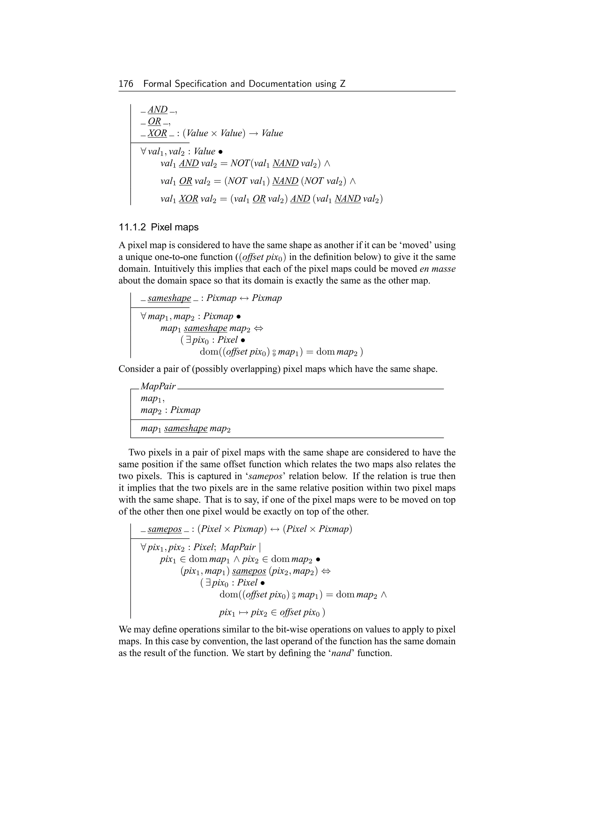

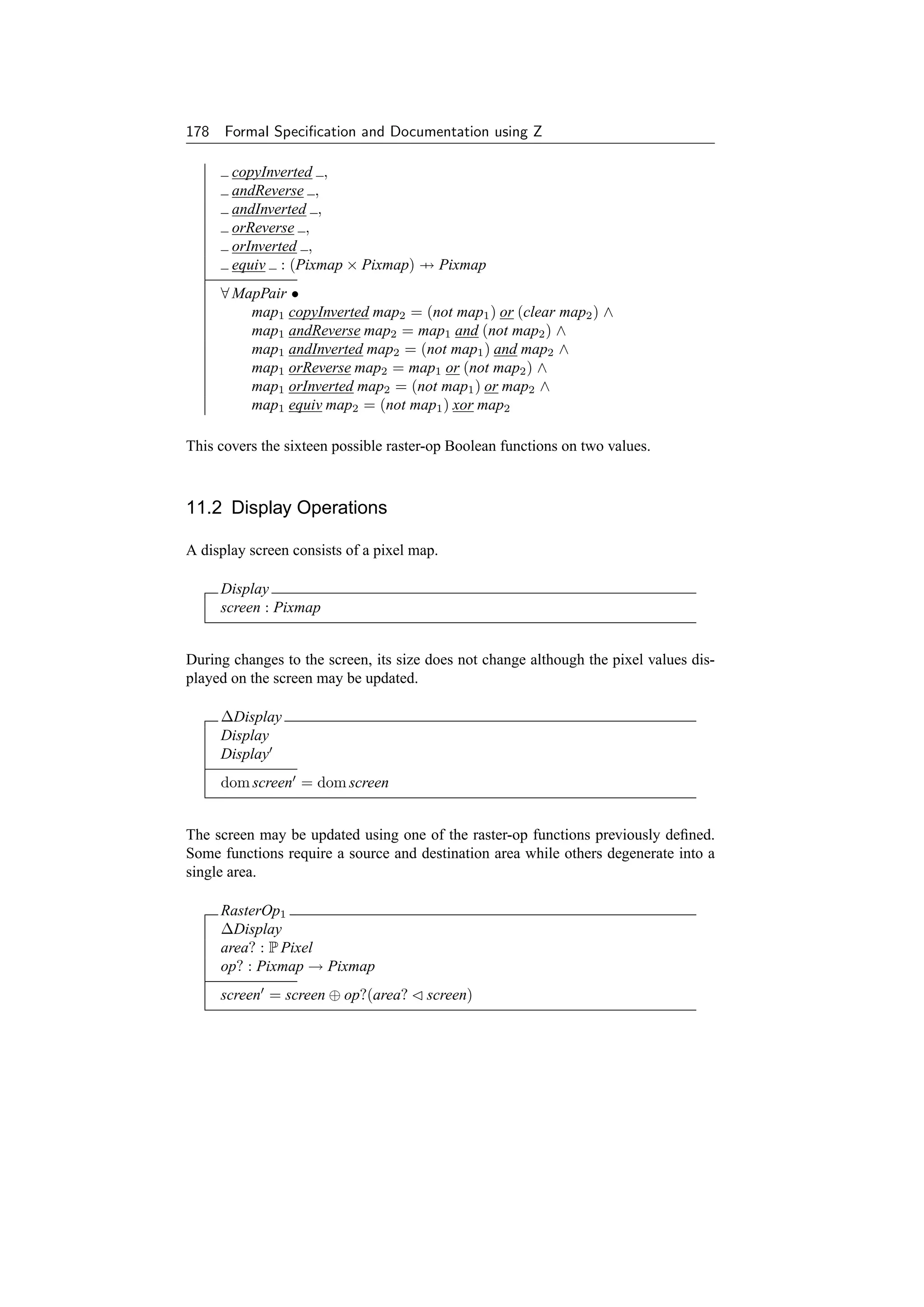
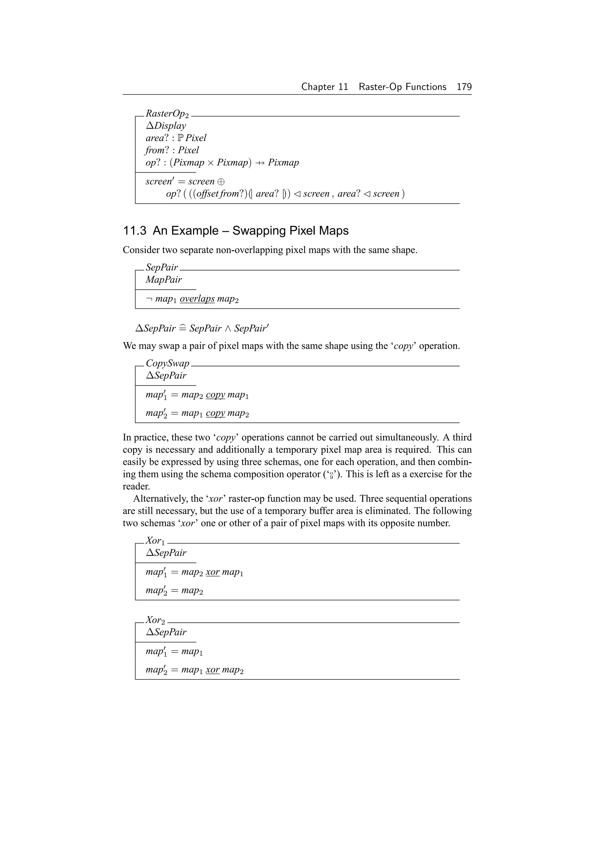
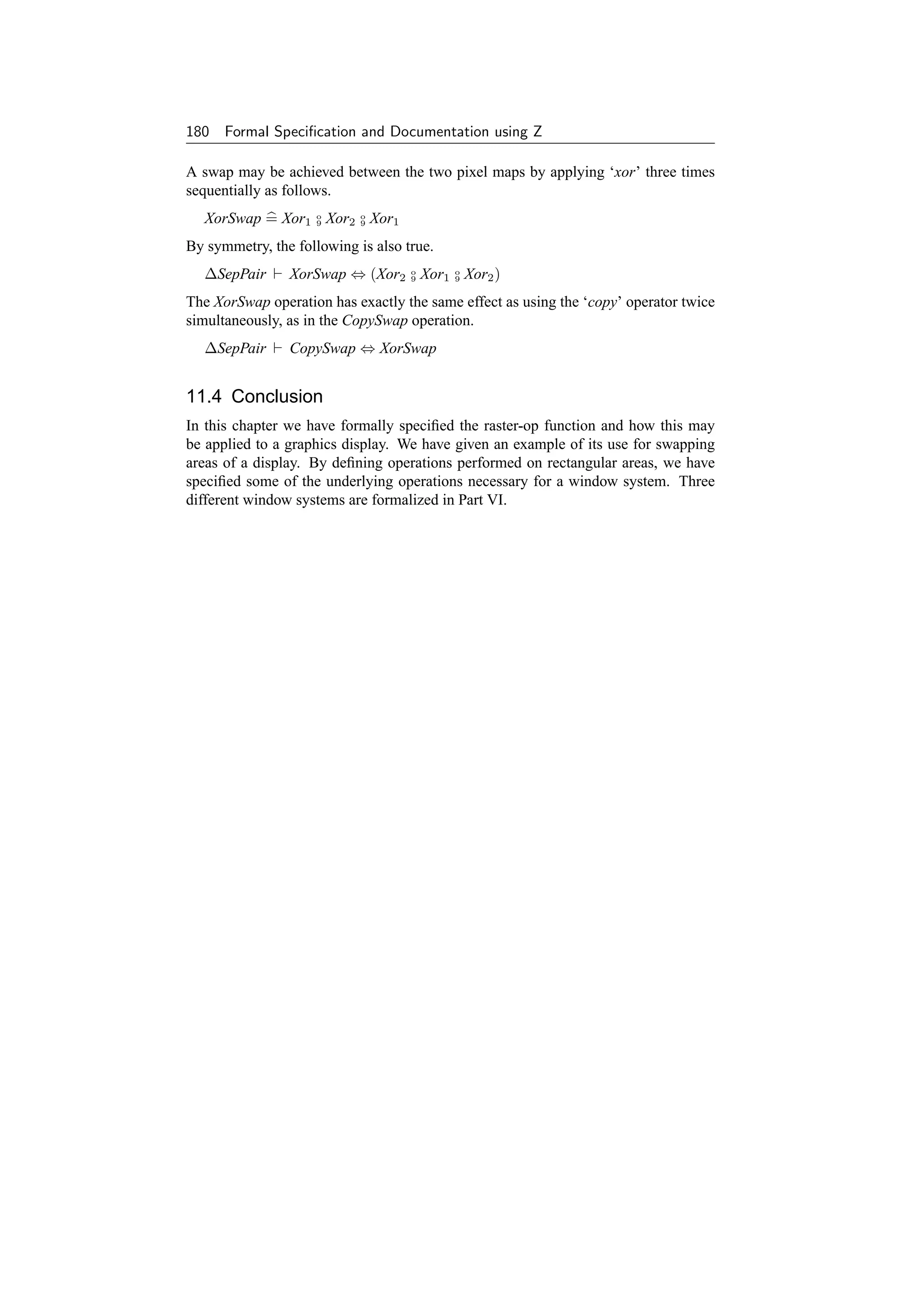

![Chapter 12
The ITC ‘WM’ Window
Manager
WM, part of the ‘Andrew’ distributed system, is a window manager developed at
the Information Technology Center (ITC) at Carnegie-Mellon University (CMU)
[356, 415]. This runs on UNIX workstations designed to be networked on a very
large scale (c5,000–10,000 nodes for the entire campus at CMU). Because of the
distributed file system, any authorized person may also use any other workstation
on the network, and indeed create windows on other workstations remotely. Sub-
sequently this was implemented as the Andrew Toolkit under the X window system
[325]. This chapter, and the following two chapters on the Blit and X window
systems respectively, make use of graphical concepts defined in Part V.
12.1 System State
The state of the system is introduced in stages. In this model we consider a single
machine for simplicity since we are concerned with how the window manager works
rather than how the network operates. Operations over the network will be detailed
later.
Each window has a number of pieces of information associated with it. These in-
clude a header area for titles and other information, and a separate body area to hold
the actual contents of the window. These do not overlap and together they make up the
pixel map of the displayed window. In practice, the header is a thin rectangular area
just above its associated body.
Map
header, body, map : Pixmap
area : P Pixel
header, body partition map
area = dom map
The user can request a window to lie within a specified range of dimensions and can
also explicitly ask for a window body to be hidden from view or exposed on the screen.
Each window has a title which can be set by the user. This information is used by the
window manager to lay out the window on the screen, although there is no guarantee
that what the user asks for is what the user gets!
183](https://image.slidesharecdn.com/zbook-130114070646-phpapp01/75/Zbook-196-2048.jpg)

![Chapter 12 The ITC ‘WM’ Window Manager 185
MaxWindows : N
MaxWindows = 20
We can include this limitation in our model of the state.
WM2 = [ WM1 | #windows ≤ MaxWindows ]
The size of a window on the user’s display is one of the resources that the Window
Manager allocates. A program can request a given size, and WM will take the re-
quested size into account when making decisions, but it does not guarantee a particular
size. This process is modelled as a function of the system. The number of windows is
not changed by this function. Additionally, control information supplied by the user is
left unchanged.
WINDOWS == Window → Info
WM
WM2
adjust : WINDOWS → WINDOWS
∀ w, w : WINDOWS | w = adjust w •
#w = #w ∧
w o
9 (λ Info • θControl) = w o (λ Info • θControl)
9
Initially there are no windows and the current window is undefined.
InitWM
WM
windows = ∅
current = Undefined
Operations change the state of the system. However the background and hence the
size of the screen remains constant. Additionally the algorithm to adjust the size of
windows does not change.
∆WM
WM
WM
background = background
adjust = adjust
Sometimes the state of the system is unaffected during an operation.
ΞWM = [ ∆WM | θWM = θWM ]
Many operations are concerned with the current window. Hence we define a schema
giving a partial specification covering all common aspects of such operations. This](https://image.slidesharecdn.com/zbook-130114070646-phpapp01/75/Zbook-198-2048.jpg)
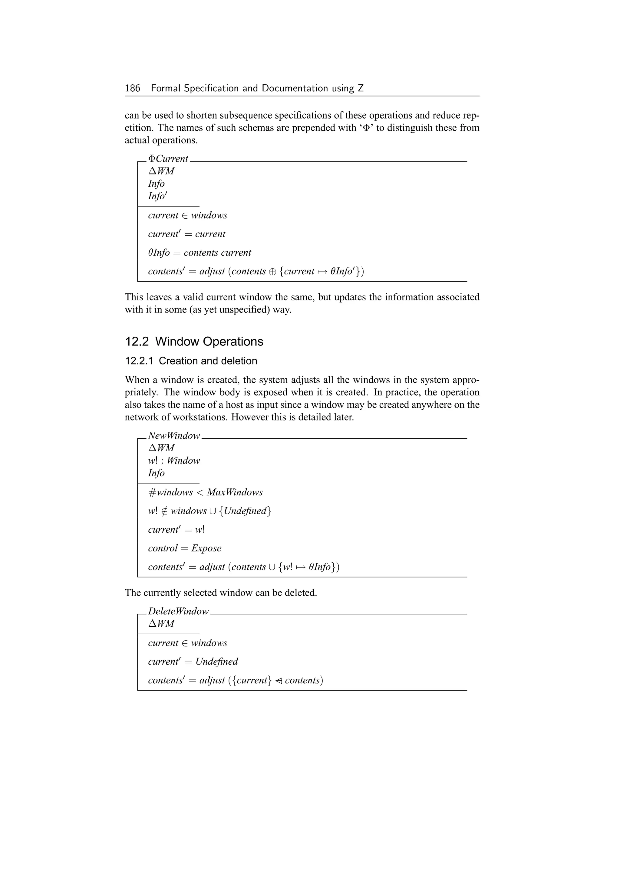


![Chapter 12 The ITC ‘WM’ Window Manager 189
ClearWindow
ΦCurrent
header = header
body = setval White body
title = title
control = control
xylimits = xylimits
Other operations supplied by the WM library include line, text and string drawing,
raster operations, operations to save and restore parts of the picture, input handling,
menus, mouse input, etc. In addition, new operations may be added; at the time that
this specification was originally formulated WM was still under development.
12.3 Errors
There is a Null window identifier which is never a valid window.
Null : Window
WMerr = [ WM | Null ∈ windows ]
/
∆WM and ΞWM are redefined appropriately.
Some operations return a window identifier. If this is non-null then the operation is
successful.
SuccessWM
∆WMerr
w! : Window
w! = Null
Alternatively a error may occur. There is a limit on the number of windows which
WM can handle. This could cause an error when creating a new window.
TooManyWindows
ΞWMerr
w! : Window
#windows ≥ MaxWindows
w! = Null
We can now make the operation to create a new window total.
NewWindow1 = (NewWindow ∧ SuccessWM )
∨ TooManyWindows
The current window may be undefined when one is required:](https://image.slidesharecdn.com/zbook-130114070646-phpapp01/75/Zbook-202-2048.jpg)
![190 Formal Specification and Documentation using Z
NoCurrentWindow
ΞWMerr
current = Undefined
Many operations may return with this error:
DeleteWindow1 = DeleteWindow ∨ NoCurrentWindow
SetDimensions1 = SetDimensions ∨ NoCurrentWindow
GetDimensions1 = GetDimensions ∨ NoCurrentWindow
SetTitle1 = SetTitle ∨ NoCurrentWindow
ClearWindow1 = ClearWindow ∨ NoCurrentWindow
An invalid window may be selected:
InvalidWindow
ΞWMerr
w? : Window
w? ∈ windows
/
SelectWindow1 = SelectWindow ∨ InvalidWindow
A window may always be hidden or exposed, even if this does not affect its state, so
no error schemas are required for the HideMe and ExposeMe operations.
12.4 The ITC Network
In practice, as mentioned previously, there are many window managers, each running
on a host workstation on a large network. Some hosts are running WM. All work-
stations have unique host names and all windows have unique identifiers across the
network.
ITC
hosts : P String
wms : String → WM
dom wms ⊆ hosts
disjoint (wms o (λ WM • windows))
9
Initially there are no hosts (and hence no window managers) on the network.
InitITC = [ ITC | hosts = ∅ ]
Operations cause changes on the network.
∆ITC = ITC ∧ ITC
Hosts can be added to the system (e.g., booting up) and removed (e.g., crashing or
powering down).](https://image.slidesharecdn.com/zbook-130114070646-phpapp01/75/Zbook-203-2048.jpg)
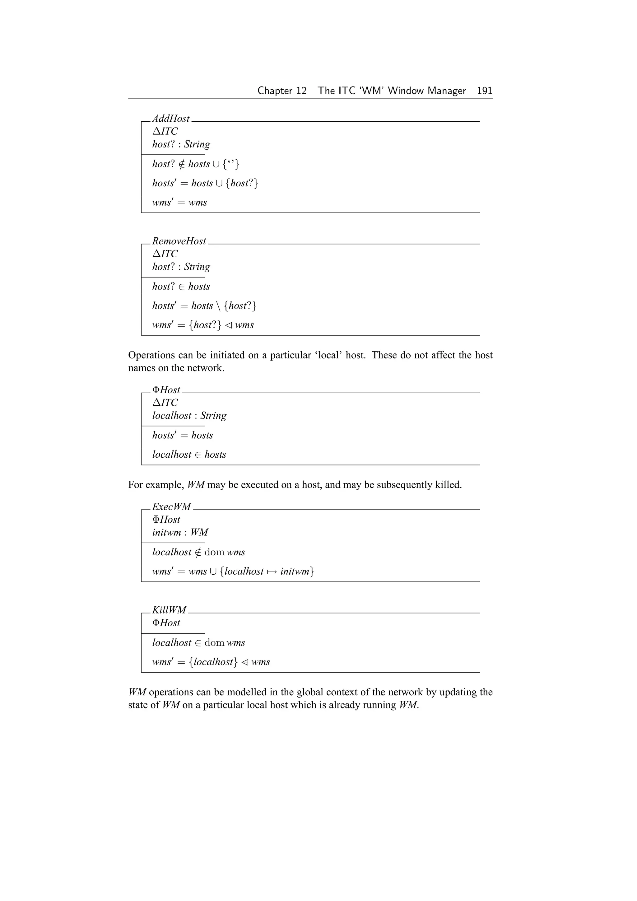
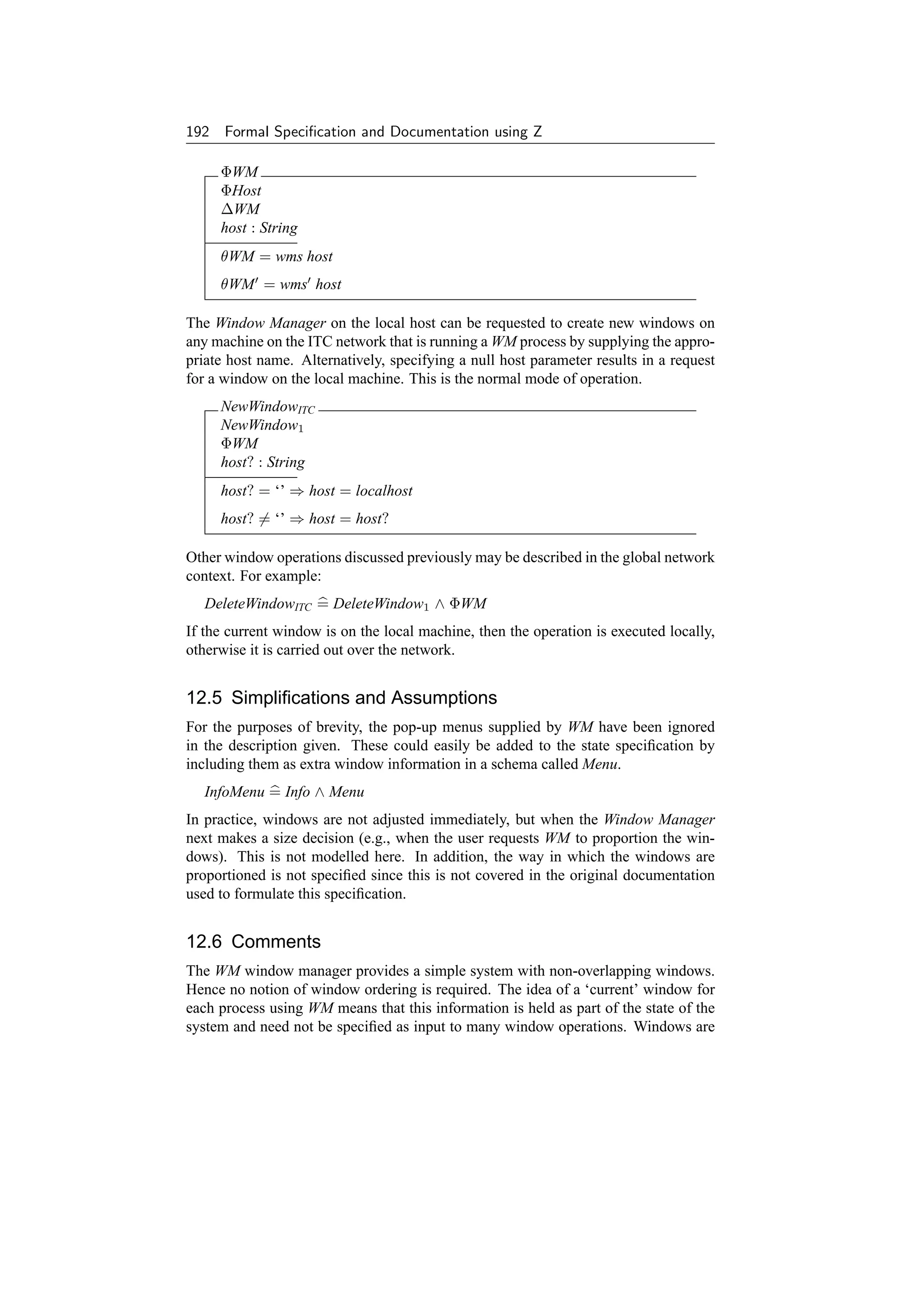


![Chapter 13
Blit Windows
The Blit [16, 329], developed at Bell Labs, Murray Hill, is more like an intelligent
terminal than a workstation. It is diskless and, at the time of its design, interacted
with a remote host running the Bell Labs Eighth Edition UNIX via a 9600 baud
(slow) RS-232 serial line. It has its own simple process scheduler and a bit-mapped
display. Programs can be run on the Blit (downloaded from the remote host), on
the remote host itself using a standard window terminal emulator process on the
Blit, or on both using two special purpose programs which interact with each other
over the serial line. Deciding how to split a program between the Blit and remote
host is a tricky but interesting problem.
13.1 System State
The Blit contains ‘layers’ which are analogous to windows on most other systems.
However there is no protection between layers. Each layer has an rectangular region
on the screen associated with it. Here we model this simply as a partial function from
pixel points to values.
Layer == Window
Point == Pixel
Each pixel point is two-valued – i.e., each window is a simple bit map.
Zsize = 1
Several layers (with associated rectangular windows) may exist simultaneously. The
layers are ordered as a sequence for reasons that will be seen in a moment. There is
an invalid null layer for error returns (see later).
NullLayer : Layer
195](https://image.slidesharecdn.com/zbook-130114070646-phpapp01/75/Zbook-208-2048.jpg)
![196 Formal Specification and Documentation using Z
Blit0
layers : seq Layer
windows : Layer → Rectangle
rects : seq Rectangle
ran layers = dom windows
NullLayer ∈ ran layers
/
rects = layers o windows
9
Several processes may also exist simultaneously in the Blit. Each process has an
associated program and state. A process may be disabled or enabled. However the
rest of this specification is not concerned with the state of processes, but it is included
here for completeness. Each process is normally associated with a layer. Creating a
process without a layer or vice versa is dangerous.
[Program, StateInfo]
Proc
prog : Program
state : StateInfo
l : Layer
The Blit includes no window ‘manager’ as such since any process has access to the
entire screen. There are a series of processes in the system each identified uniquely by
a process id. There is a null invalid id which is returned by operations to indicate an
error. One of the processes may be assigned to receive mouse and keyboard events.
[Id]
NullId : Id
Blit1
Blit0
procs : Id → Proc
receiver : Id
NullId ∈ dom procs
/
receiver ∈ dom procs ∪ {NullId}
∀ proc : ran procs • proc.l ∈ ran layers ∪ {NullLayer}
A process may be associated with a default terminal emulation program if desired.
Blit2 = [ Blit1 ; default : Program ]
The background may be considered as another layer which defines the size of the
screen. The display consists of all the layers overlaid on top of the background. All
layers are contained within the background. The order is determined from the position
in the sequence (first at the bottom, last on top).](https://image.slidesharecdn.com/zbook-130114070646-phpapp01/75/Zbook-209-2048.jpg)
![Chapter 13 Blit Windows 197
Blit
Blit2
screen, background : Rectangle
dom(⊕/rects) ⊆ dom background
screen = background ⊕ (⊕/rects)
Initially there are no layers or processes in the system.
InitBlit
Blit
layers =
procs = ∅
receiver = NullId
Operations do not change the default terminal program or the background of the dis-
play.
∆Blit
Blit
Blit
default = default
background = background
Some operations do not affect the state of the Blit.
ΞBlit = [ ∆Blit | θBlit = θBlit ]
Often operations only affect layers and all the processes in the system are left unaf-
fected.
ΦLayer
∆Blit
procs = procs
receiver = receiver
Similarly, processes are often changed while leaving all the layers in the system unaf-
fected.
ΦProc
∆Blit
layers = layers
windows = windows](https://image.slidesharecdn.com/zbook-130114070646-phpapp01/75/Zbook-210-2048.jpg)
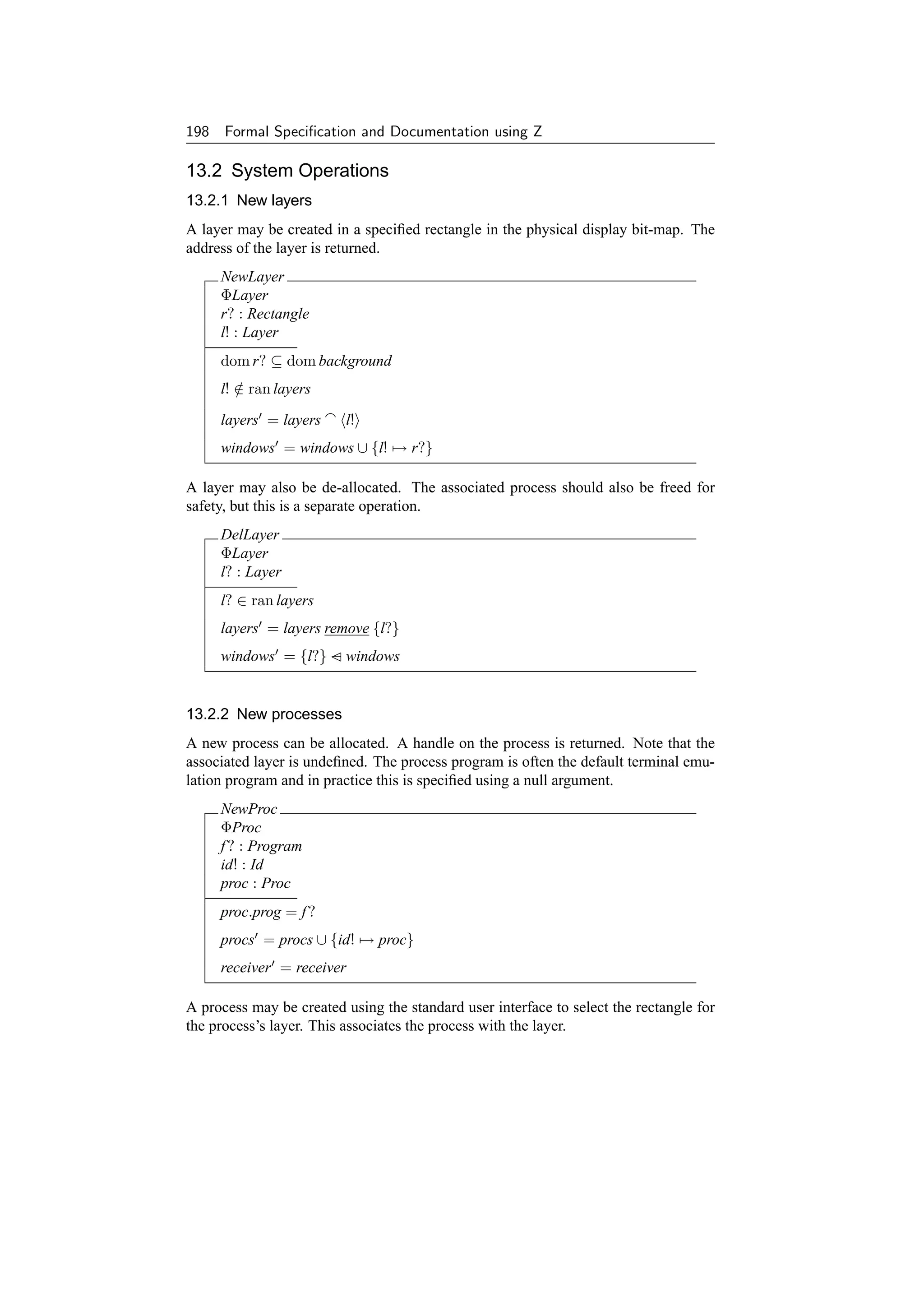
![Chapter 13 Blit Windows 199
NewWindow0 = NewProc o NewLayer
9
NewWindowBlit = [ NewWindow0 | l! = proc.l ]
A layer may be selected so that the process in that layer becomes the receiver of mouse
and keyboard events.
ToLayer
ΦProc
l? : Layer
proc : Proc
proc ∈ ran procs
l? = proc.l
procs = procs
receiver = procs∼ proc
The process whose layer is indicated by the mouse may be returned.
GetProc
ΞBlit
l? : Layer
proc! : Proc
proc! ∈ ran procs
proc!.l = l?
Alternatively, a handle on all the processes in the system may be returned.
GetProcTab
ΞBlit
procs! : Id → Proc
procs! = procs
13.2.3 Mouse operations
The Blit includes a mouse. This controls the position of a cursor on the screen. Ad-
ditionally, any combination of the three buttons on the mouse may be pressed at any
time.
Buttons ::= Button1 | Button2 | Button3
Mouse
xy : Point
buttons : P Buttons
Some pixel positions on the display screen may be associated with a particular layer.](https://image.slidesharecdn.com/zbook-130114070646-phpapp01/75/Zbook-212-2048.jpg)
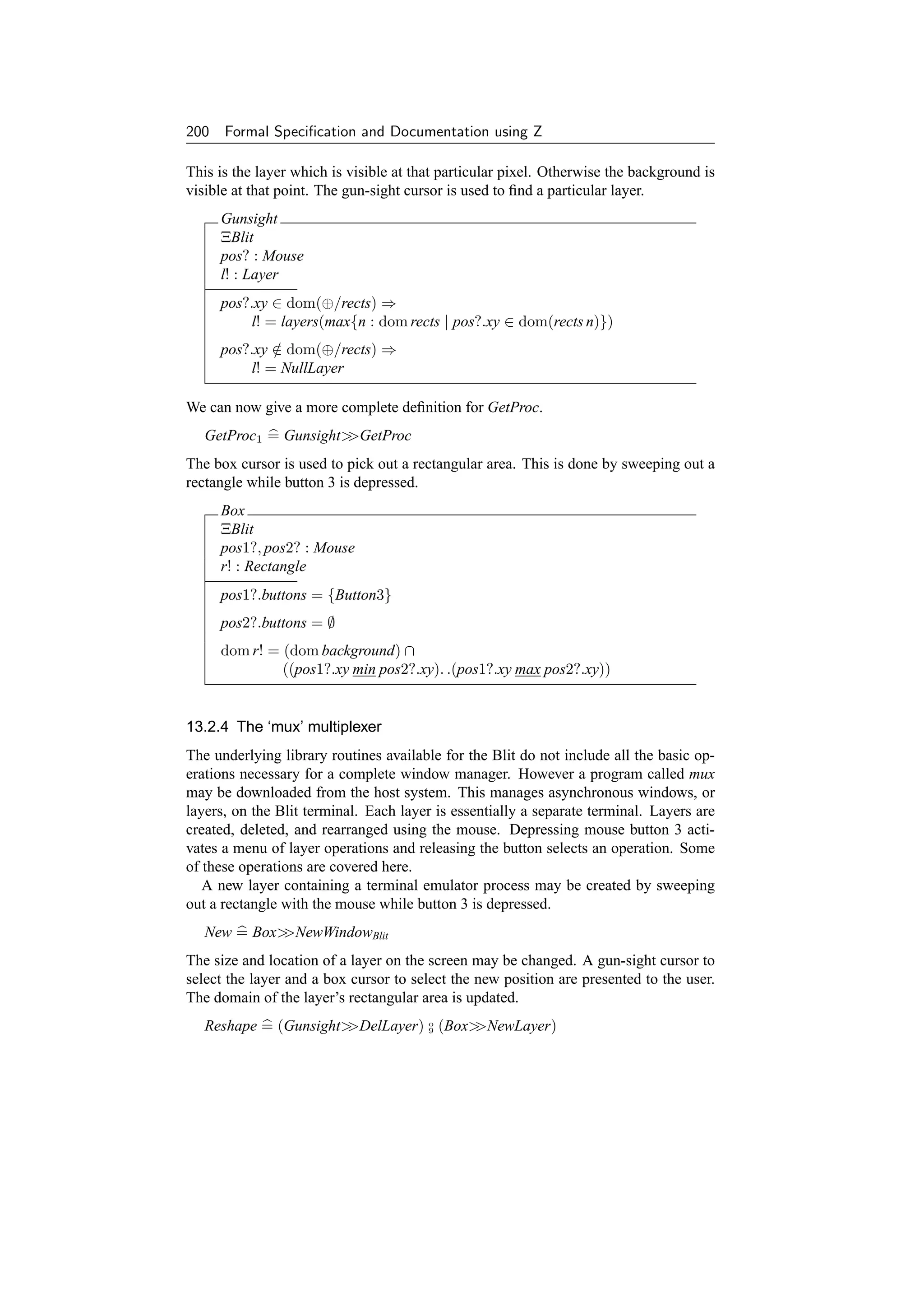

![202 Formal Specification and Documentation using Z
InvalidLayer
ΞBlit
l? : Layer
l? ∈ ran layers
/
A layer must exist to delete it or make it the current receiver.
DelLayer1 = DelLayer ∨ InvalidLayer
ToLayer1 = ToLayer ∨ InvalidLayer
Some operations return no errors.
GetProcTab1 = GetProcTab
13.4 Simplifications, Assumptions and Comments
Many cursor and mouse operations and other graphics operations have been ignored
for brevity.
The documentation [16] states that the associated process must be freed when a
layer is de-allocated. However it does not make it clear how to do this so this has not
been specified.
The Blit is different from most other window systems in that it is a diskless intel-
ligent terminal which interacts with a remote host in normal operation. In addition
there is no protection between processes and layers within the Blit. Hence care must
be exercised when programming it, but in return this allows greater flexibility and
versatility.
While the Blit was an interesting research exercise, it never achieved widespread
use. In the next chapter, we consider another window system that has come to domi-
nate the UNIX-based workstation market, namely X.](https://image.slidesharecdn.com/zbook-130114070646-phpapp01/75/Zbook-215-2048.jpg)
![Chapter 14
The X Window System
X [357, 358, 359] is a network transparent windowing system developed at the
Massachusetts Institute of Technology (MIT) and designed to run under UNIX. The
X display server distributes user input to, and accepts output requests from vari-
ous client programs either on the same machine or over a network. This chapter
documents (an early version of) some of the C library calls available to X users
[360]. Some of the graphical operations available under X have been documented
elsewhere [144]. X has subsequently become an important window system in the
UNIX workstation market, and is being developed further by the X Consortium, an
independent not-for-profit company formed in 1993 as a successor to the MIT X
Consortium.
14.1 System State
The state of the X system is introduced in simple stages in order to build up the con-
cepts involved. This is done by redefining a state schema called X in terms of itself
and a series of manageably sized state definition fragments.
All the windows in an X server are arranged in a strict hierarchy. At the top of the
hierarchy is the ‘root’ window. Each window has a parent except the root window.
Child windows may in turn have their own children. Each window, including the root
window, may be considered to consist of a pixel map in this simple description.
X0
root : Window
children : P Window
parents : Window → Window
subwindows : Window ↔ Window
windows : Window → Pixmap
root ∈ children
/
children = dom parents
subwindows = parents∼
dom windows = children ∪ {root}
Subwindows are displayed in a particular order within their parent window. This may
203](https://image.slidesharecdn.com/zbook-130114070646-phpapp01/75/Zbook-216-2048.jpg)
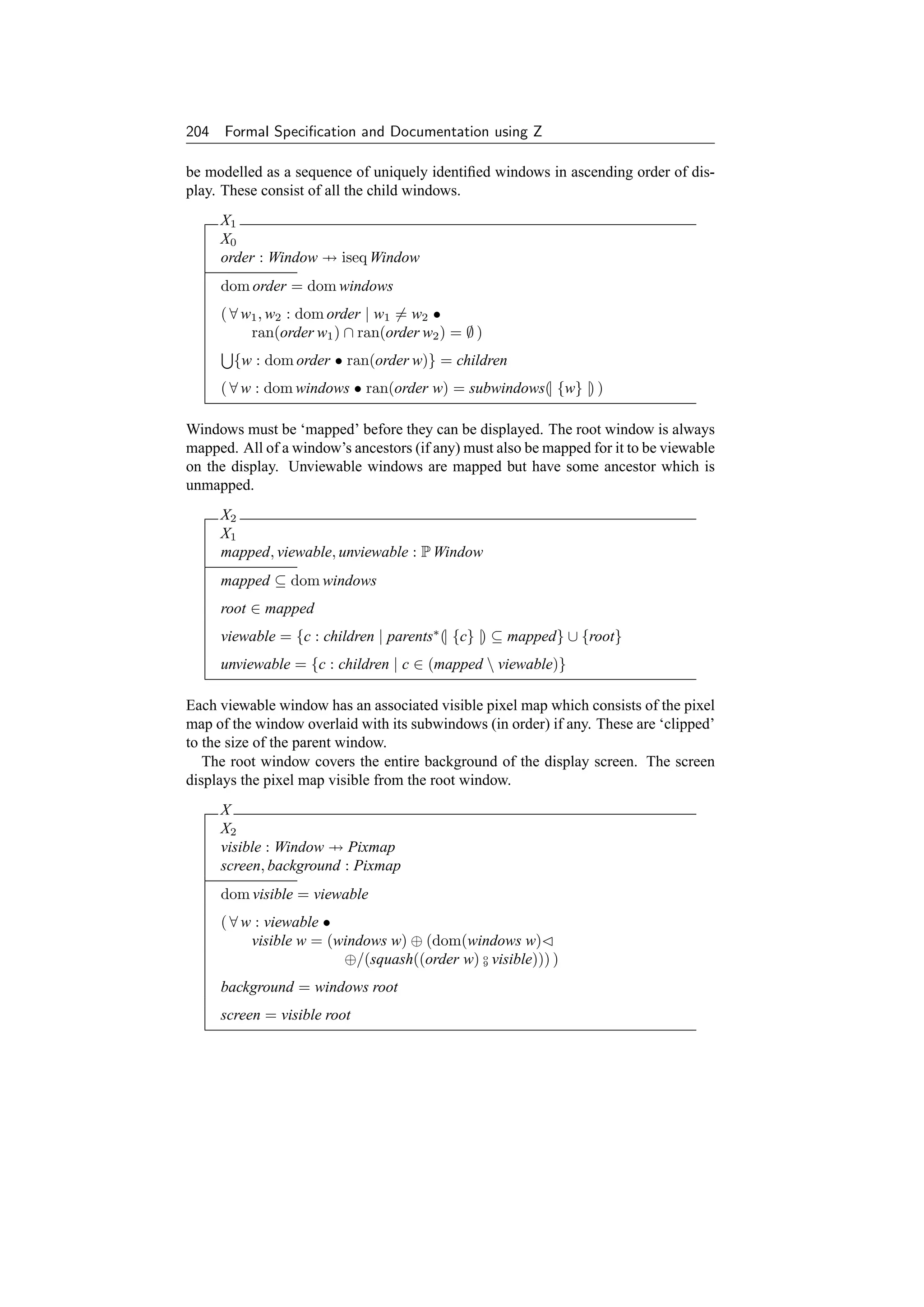
![Chapter 14 The X Window System 205
Initially there are no children and only the root window is mapped. Hence only the
background is displayed.
InitX
X
windows = {root → background }
order = {root → }
mapped = {root }
Thus there are no child windows:
InitX children = ∅
Proof:
InitX
{predicate in InitX}
⇒ windows = {root → background }
{law of ‘dom’}
⇒ dom windows = {root }
{predicate in X }
⇒ children ∪ {root } = {root }
{since root ∈ children from X }
/
⇒ children = ∅
Such reasoning is normally only done informally in a designer’s head; confirming such
properties serves to increase the confidence that a specification does actually describe
what is wanted.
Consider changes in the window system. The root window identifier and the back-
ground of the screen do not change.
∆X
X
X
root = root
background = background
Sometimes the state of the system is unaffected during an operation.
ΞX = [ ∆X | θX = θX ]
We can now consider operations on the state of the system; initially, error-free opera-
tions will be presented for simplicity. Error conditions are covered later.](https://image.slidesharecdn.com/zbook-130114070646-phpapp01/75/Zbook-218-2048.jpg)

![Chapter 14 The X Window System 207
We also wish to destroy windows. Given a particular window, we may wish to destroy
a set of windows which are associated with it. We can define a partial specification to
do this as a schema. Exactly which windows are to be destroyed is not specified for
the present.
ΦDestroy
∆X
w? : Window
destroy : P Window
w? ∈ children
windows = destroy − windows
( ∀ w : dom windows • order w = (order w) remove destroy )
mapped = mapped destroy
We may wish all subwindows, as well as the window itself, to be destroyed.
DestroyWindow = [ ΦDestroy | destroy = subwindows∗ (| {w?} |) ]
Alternatively, we may wish to just destroy the subwindows under the specified win-
dow.
DestroySubwindows = [ ΦDestroy | destroy = subwindows+ (| {w?} |) ]
Note that the ‘root’ background window cannot be destroyed using these operations.
Only child windows may be destroyed.
DestroyWindow root ∈ dom windows
Proof: directly from the invariant dom windows = children ∪ {root} in the schema
X0 . However, we may wish to investigate this further, to see what preconditions are
introduced by such a constraint.
14.2.2 Manipulating windows
A window, and all its ancestors, must be ‘mapped’ to be visible on the screen. However
a mapped window may still be invisible if it is obscured by a sibling window.
Mapping operations require a child window to be specified. The hierarchical rela-
tionships between windows and the contents of the windows are left unaffected.
ΦMap
∆X
w? : Window
w? ∈ children
windows = windows
Mapping a window raises the window and all its subwindows which have had map
requests. Mapping a window which is already mapped has no effect on the screen – it
does not raise it.](https://image.slidesharecdn.com/zbook-130114070646-phpapp01/75/Zbook-220-2048.jpg)

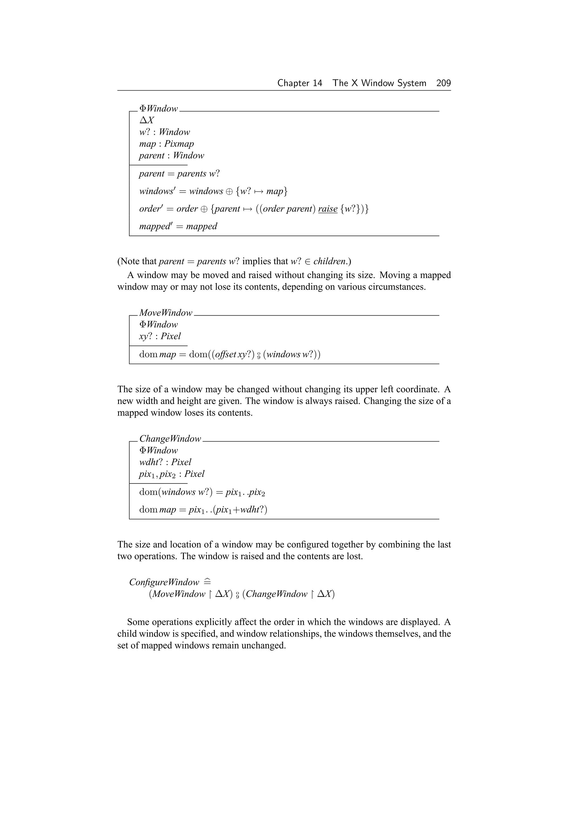
![210 Formal Specification and Documentation using Z
ΦOrder
∆X
w? : Window
parent : Window
suborder, suborder : seq Window
parent = parents w?
windows = windows
suborder = order parent
order = order ⊕ {parent → suborder }
mapped = mapped
(Note that as for the ΦWindow schema, parent = parents w? implies that w? ∈
children.)
A window may be ‘raised’ so that no sibling window obscures it. If the windows
are regarded as overlapping sheets of paper stacked on a desk, then raising a window
is analogous to moving the sheet to the top of the stack, while leaving its position on
the desk the same.
RaiseWindow =
[ ΦOrder | suborder = suborder raise {w?} ]
A window may also be ‘lowered’ in a complementary fashion. If the windows are
regarded as overlapping sheets of paper stacked on a desk, then lowering a window is
analogous to moving the sheet to the bottom of the stack, while leaving its position on
the desk the same.
LowerWindow =
[ ΦOrder | suborder = suborder lower {w?} ]
Overlapping mapped subwindows of a particular window may be raised or lowered
in a circular manner. The set of these windows is identified. If it is non-empty, the
ordering of the window’s children is updated; otherwise it is left unchanged.](https://image.slidesharecdn.com/zbook-130114070646-phpapp01/75/Zbook-223-2048.jpg)
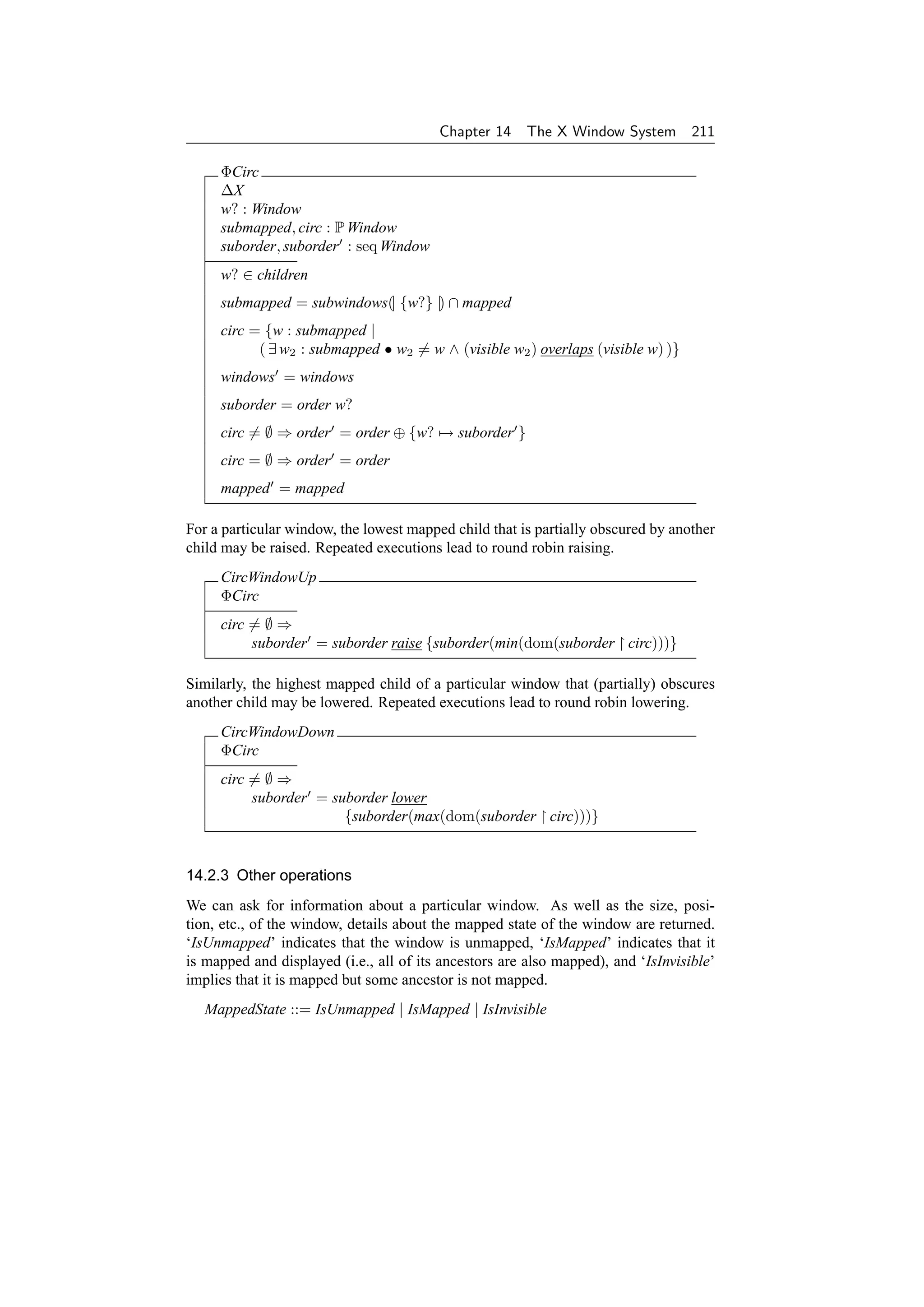
![212 Formal Specification and Documentation using Z
QueryWindow
ΞX
w? : Window
info! : Pixmap
mapped! : MappedState
w? ∈ children
info! = windows w?
w? ∈ mapped ⇒
/
mapped! = IsUnmapped
parents∗ (| {w?} |) ⊆ mapped ⇒
mapped! = IsMapped
w? ∈ mapped ∧ ¬ (parents+ (| {w?} |) ⊆ mapped) ⇒
mapped! = IsInvisible
We can also find out the window identifiers of the parent and all the children (and
hence the number of children) for a particular window. The children are listed in
current stacking order, from bottommost (first) to topmost (last).
QueryTree
ΞX
w? : Window
parent! : Window
children! : seq Window
parent! = parents w?
children! = order w?
The X system includes many other operations. These include more detailed window
operations, mouse operations, graphics for line drawing and fill operations, screen
raster operations, moving bits and pixels to and from the screen, storing and freeing bit
maps and pixel maps, cursor definition, colour operations, font manipulation routines,
text output to a window, and so on. However the operations covered give an indication
of the basic windowing facilities available under the X system.
14.3 Errors
Many operations return a status report signalling success or failure of the operation.
Let this be denoted ‘Status’. Often a ‘NULL’ status indicates success and a non-NULL
status indicates failure.
[Status]
NULL : Status
The operations covered so far detail what should happen in the event of no errors. In
this case we also wish to report the fact that the operation was successful.](https://image.slidesharecdn.com/zbook-130114070646-phpapp01/75/Zbook-225-2048.jpg)


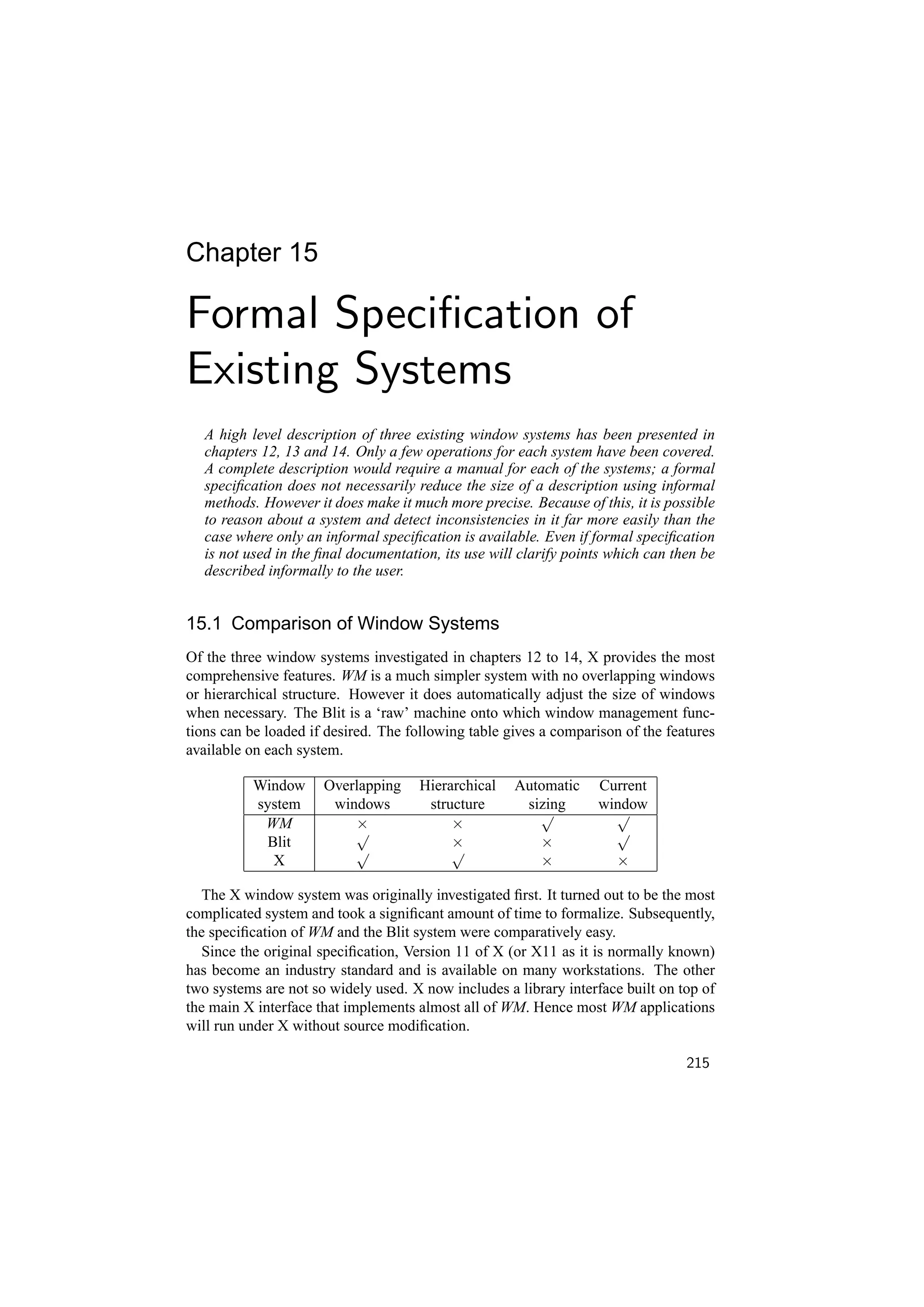
![216 Formal Specification and Documentation using Z
15.2 Case Study Experience
The specifications of the window systems presented here were originally undertaken
as part of the Distributed Computing Software (DCS) Project at the Programming
Research Group within the Oxford University Computing Laboratory [43, 47]. As
well as designing and documenting network services using a formal notation, part of
the brief of the DCS project was to undertake case studies of existing systems and to
formally specify parts of them in Z to gain a greater understanding of their operation.
Originally it had been hoped to compare parts of a number of distributed systems
using Z. However, the authors of potential systems for investigation could only supply
academic papers (not enough information) or the source code (too much information).
What was required was some form of informal documentation for the system. Be-
cause window systems are used directly by users, there seems to be more readable
documentation for such systems.
In each case, omissions and ambiguities in the documentation were discovered by
attempting to formalize the system. Where necessary, intelligent guesses were made
about the actual operation. These were usually correct, but not always.
Subsequently, the formal specifications could be used to update the existing docu-
mentation, or even rewrite it from scratch. Although Z has been developed as a design
tool, it is also well suited for post hoc specifications of existing systems, and for de-
tecting and correcting errors and anomalies in the documentation of such systems [41].
The most important stage of formalizing a system is selecting the right level of
abstraction for modelling its state. This is normally an iterative process. On attempting
to specify an operation one often needs to backtrack to change the abstract state of the
system. In particular, extra state components can be convenient to provide different
views of the system depending on the operation involved.
There are likely to be some inconsistencies between the specifications given in
chapters 12 to 14 and the actual operation of the systems described. This is due to
impreciseness and misunderstanding of the informal documentation used to formulate
these specifications. This illustrates one of the reasons for using formal specifica-
tion techniques – to avoid ambiguity or vagueness and to aid precise communication
of ideas. Because of this, formal notation forces issues to the surface much earlier
in the design process than when using informal description techniques such as natu-
ral language and diagrams. Difficult areas of the design cannot be ignored until the
implementation stage. This reduces the number of backtracks necessary round the
design/implementation cycle.
Additionally, using formal specification techniques should reduce maintenance costs
since more of the errors in a system will be discovered before it is released into the
field. Although specification and design costs will be increased, implementation and
maintenance costs should be lower, reducing overall costs.
Formally specifying an existing system could be particularly useful if it is to be
re-engineered to comply with modern software engineering standards. In such cases
there could be costs benefits by taking such an approach [319].](https://image.slidesharecdn.com/zbook-130114070646-phpapp01/75/Zbook-229-2048.jpg)

![Acknowledgements
The work for the book was largely supported by the UK Science and Engineering
Research Council (SERC) and its successor, the Engineering and Physical Sciences
Research Council (EPSRC). The author was funded by the SERC on the Distributed
Computing Software project (grant number GR/C/9786.6) from 1985 to 1987, on the
Software Engineering project (on an SERC rolling grant) from 1987 to 1989, on the
collaborative Information Engineering Directorate safemos project (GR/F36491)
from 1989 to 1993 and is currently funded on EPSRC grant number GR/J15186 in-
vestigating Provably Correct Hardware/Software Co-design.
Many people have provided inspiration for and have contributed further over the
years to the material presented here. These include: Rosalind Barden, Peter Breuer,
Stephen Brien, David Brown, Jim Davies, Neil Dunlop, Jim Farr, Roger Gimson, Tim
Gleeson, Mike Gordon, Anthony Hall, Ian Hayes, He Jifeng, Mike Hinchey, Tony
Hoare, Darrel Ince, Steve King, Kevin Lano, Carroll Morgan, John Nicholls, Paritosh
Pandya, Philip Rose, Jeff Sanders, Jane Sinclair, Ib Sørensen, Mike Spivey, Victoria
Stavridou, Susan Stepney, Bernard Sufrin, Stig Topp-Jørgensen and Jim Woodcock.
Please forgive me if I have inadvertently omitted anyone; I am extremely grateful to
the above for providing such a rich environment at Oxford and elsewhere.
Mike Gordon helped in particular with the section on schemas in Chapter 3. Car-
roll Morgan and Roger Gimson were the original team on the Distributed Computing
Software Project, as reported in Chapter 4. David Brown designed the example in
Chapter 7. Jim Farr undertook an MSc. project under my supervision, on which the
specification of the Transputer instruction set presented in Chapter 9 is partially based.
Rob Pike (ATT), Jim Gettys (DEC), C. Neuwirth (CMU), Dave Presotto (ATT),
David Rosenthal (CMU), Mahadev Satyanarayanan (CMU), Bob Scheifler (MIT) and
Bill Weihl (MIT) helped provide material, information and access to the window sys-
tems described in Part VI. Susan Stepney and Rosalind Barden of Logica Cambridge
Limited initiated the literature guide in Appendix C as part of the collaborative ZIP
project. Jane Sinclair read the manuscript as it neared completion and gave some
valuable comments.
The book has been formatted using Leslie Lamport’s LTEX document preparation
A
system [251]. The Z notation has been formatted and type-checked throughout, using
Mike Spivey’s f UZZ package [380].
Finally, thank you to my family, Jane, Alice and Emma, for being so patient and
providing a wonderful environment at home.
219](https://image.slidesharecdn.com/zbook-130114070646-phpapp01/75/Zbook-232-2048.jpg)


![Appendix A Information on Z 225
and Z FORUM, as well as a selection of other Z-related text files. Send an email mes-
sage containing the command ‘help’ to archive-server@comlab.ox.ac.uk
for further information on how to use the server. A command of ‘index z’ will list
the Z-related files. If you have serious trouble accessing the archive server, please
contact the address archive-management@comlab.ox.ac.uk.
A.6 Z Tools
Various tools for formatting, type-checking and aiding proofs in Z are available. A
free LTEX style file and documentation can be obtained from the OUCL archive
A
server. Access ftp://ftp.comlab.ox.ac.uk/pub/Zforum/zed.sty and
the zguide.tex file in the same directory via anonymous FTP. The newer styles
‘csp zed.sty’ which uses the new font selection scheme and ‘zed-csp.sty’
which supports LTEX2e handle CSP and Z symbols, and are available in the same
A
location. A style for Object-Z ‘oz.sty’ with a guide ‘oz.tex’ is also accessible.
The f UZZ package [380], a syntax and type-checker with a LTEX style option and
A
fonts, is available from the Spivey Partnership, 10 Warneford Road, Oxford OX4 1LU,
UK. It is compatible with the second edition of Spivey’s Z Reference Manual [381].
Contact Mike Spivey (email Mike.Spivey@comlab.oxford.ac.uk) for fur-
ther information. Alternatively send the command ‘send z fuzz’ to the OUCL
archive server or access ftp://ftp.comlab.ox.ac.uk/pub/Zforum/fuzz
for brief information and an order form.
CADiZ [237], a UNIX-based suite of tools for checking and typesetting Z specifica-
tions. CADiZ also supports previewing and interactive investigation of specifications.
It is available from York Software Engineering, University of York, York YO1 5DD,
UK (tel +44-1904-433741, fax +44-1904-433744). CADiZ supports a language like
that of the Z Base Standard (Version 1.0). A particular extension allows one speci-
fication document to import another, including the mathematical toolkit as one such
document. Typesetting support is available for both troff and for LTEX. Browsing
A
operations include display of information deduced by the type-checker (e.g. types of
expressions and uses of variables), expansion of schemas, pre- and postcondition cal-
culation, and simplification by the one-point rule. Work is on-going to provide support
for refinement of Z specifications to Ada programs through a literate program devel-
opment method and integrated proof facilities. Further information is available from
David Jordan at York on yse@minster.york.ac.uk.
ProofPower [236] is a suite of tools supporting specification and proof in Higher
Order Logic (HOL) and in Z. Short courses on ProofPower-Z are available as demand
arises. Information about ProofPower can be obtained automatically from ProofPower-
server@win.icl.co.uk. Contact Roger Jones, International Computers Ltd,
Eskdale Road, Winnersh, Wokingham, Berkshire RG11 5TT, UK (tel +44-1734-693131
ext 6536, fax +44-1734-697636, email rbj@win.icl.co.uk) for further details.
Zola is a tool that supports the production and typesetting of Z specifications, in-
cluding a type-checker and a Tactical Proof System. The tool is sold commercially and
available to academic users at a special discount. For further information, contact K.
Ashoo, Imperial Software Technology, 62–74 Burleigh Street, Cambridge CB1 1DJ,
UK (tel +44-1223-462400, fax +44-1223-462500, email ka@ist.co.uk).
ZTC [444] is a Z type-checker available free of charge for educational and non-](https://image.slidesharecdn.com/zbook-130114070646-phpapp01/75/Zbook-238-2048.jpg)
![226 Formal Specification and Documentation using Z
profit uses. It is intended to be compliant with the 2nd edition of Spivey’s Z Reference
Manual [381]. It accepts LTEX with zed or oz styles, and ZSL – an ASCII version
A
of Z. ZANS is a research prototype Z animator. Both ZTC and ZANS run on Linux,
SunOS 4.x, Solaris 2.x, HP-UX 9.0, DOS, and extended DOS. They are available
via anonymous FTP under ftp://ise.cs.depaul.edu/pub in the directories
ZANS-x.xx and ZTC-x.xx, where x.xx are version numbers. Contact Xiaoping Jia
jia@cs.depaul.edu. for further information.
Formaliser is a syntax-directed WYSIWYG Z editor and interactive type-checker,
running under Microsoft Windows, available from Logica. Contact Susan Stepney,
Logica UK Limited, Cambridge Division, Betjeman House, 104 Hills Road, Cam-
bridge CB2 1LQ, UK (email susan@logcam.co.uk, tel +44-1223-366343, fax
+44-1223-251001) for further information.
DST-f UZZ is a set of tools based on the f UZZ package by Mike Spivey, supplying
a Motif based user interface for LTEX based pretty printing, syntax and type check-
A
ing. A CASE tool interface allows basic functionality for combined application of
Z together with structured specifications. The tools are integrated into SoftBench.
For further information contact Hans-Martin Hoercher, DST Deutsche System-Techik
GmbH, Edisonstrasse 3, D-24145 Kiel, Germany (tel +49-431-7109-478, fax +49-
431-7109-503, email hmh@informatik.uni-kiel.d400.de).
The B-Tool can be used to check proofs concerning parts of Z specifications. The
B-Toolkit is a set of integrated tools which fully supports the B-Method for formal
software development and is available from B-Core (UK) Limited, Magdalen Cen-
tre, The Oxford Science Park, Oxford OX4 4GA, UK. For further details, contact Ib
Sørensen (email Ib.Sorensen@comlab.ox.ac.uk, tel +44-1865-784520, fax
+44-1865-784518).
Z fonts for Microsoft Windows and Macintosh are available on-line. For hyperlinks
to these and other Z tool resources see the WWW Z page tools section:
http://www.zuser.org/z/#tools
A.7 Courses on Z
There are a number of courses on Z run by industry and academia. Oxford Uni-
versity offers industrial short courses in the use Z. As well as introductory courses,
recent newly developed material includes advanced Z-based courses on proof and
refinement, partly based around the B-Tool. Courses are held in Oxford, or else-
where (e.g., on a company’s premises) if there is enough demand. For further infor-
mation, contact Jim Woodcock (tel +44-1865-283514, fax +44-1865-273839, email
Jim.Woodcock@comlab.ox.ac.uk).
Logica offer a five day course on Z at company sites. Contact Rosalind Barden
(email rosalind@logcam.co.uk, tel +44-1223-366343 ext 4860, fax +44-1223-
322315) at Logica UK Limited, Betjeman House, 104 Hills Road, Cambridge CB2
1LQ, UK.
Praxis Systems plc runs a range of Z (and other formal methods) courses. For details
contact Anthony Hall on +44-1225-444700 or jah@praxis.co.uk.
Formal Systems (Europe) Limited run a range of Z, CSP and other formal methods
courses, primarily in the US and with such lecturers as Jim Woodcock and Bill Roscoe
(both lecturers at the OUCL). For dates and prices contact Kate Pearson (tel +44-1865-](https://image.slidesharecdn.com/zbook-130114070646-phpapp01/75/Zbook-239-2048.jpg)
![Appendix A Information on Z 227
728460, fax +44-1865-201114) at Formal Systems (Europe) Limited, 3 Alfred Street,
Oxford OX1 4EH, UK.
DST Deutsche System-Technik runs a collection of courses for either Z or CSP,
mainly in Germany. These courses range from half day introductions to formal meth-
ods and Z to one week introductory or advanced courses, held either at DST, or else-
where. For further information contact Hans-Martin Hoercher, DST Deutsche System-
Techik GmbH, Edisonstrasse 3, D-24145 Kiel, Germany (tel +49-431-7109-478, fax
+49-431-7109-503, email hmh@informatik.uni-kiel.d400.de).
A.8 Publications
A searchable on-line Z bibliography is available on the World Wide Web under
http://www.zuser.org/z/bib.html
in B IBTEX format. For those without WWW access, an older compressed version is
available via anonymous FTP, together with a formatted compressed P OST S CRIPT
version:
ftp://ftp.comlab.ox.ac.uk/pub/Zforum/z.bib.Z
ftp://ftp.comlab.ox.ac.uk/pub/Zforum/z.ps.Z
Information on Oxford University Programming Research Group (PRG) Technical
Monographs and Reports, including many on Z, is available from the librarian (tel
+44-1865-273837, fax +44-1865-273839, email library@comlab.ox.ac.uk).
Formal Methods: A Survey by S. Austin G. I. Parkin, March 1993 [18] includes
information on the use and teaching of Z in industry and academia. Contact DITC
Office, Formal Methods Survey, National Laboratory, Teddington, Middlesex TW11
0LW, UK (tel +44-181-943-7002, fax +44-181-977-7091) for a copy.
The following books largely concerning Z have been or are due to be published (in
approximate chronological order):
• I. Hayes (ed.), Specification Case Studies, Prentice Hall International Series in
Computer Science, 1987. (2nd ed., 1993)
• J. M. Spivey, Understanding Z: A specification language and its formal semantics,
Cambridge University Press, 1988.
• D. Ince, An Introduction to Discrete Mathematics, Formal System Specification
and Z, Oxford University Press, 1988. (2nd ed., 1993)
• J. C. P. Woodcock M. Loomes, Software Engineering Mathematics, Addison-
Wesley, 1989.
• J. M. Spivey, The Z Notation: A reference manual, Prentice Hall International
Series in Computer Science, 1989. (2nd ed., 1992)
Widely used as the current de facto standard for Z.
• A. Diller, Z: An introduction to formal methods, Wiley, 1990.
• J. E. Nicholls (ed.), Z user workshop, Oxford 1989, Springer-Verlag, Workshops in
Computing, 1990.
• B. Potter, J. Sinclair D. Till, An Introduction to Formal Specification and Z,
Prentice Hall International Series in Computer Science, 1991.
• D. Lightfoot, Formal Specification using Z, MacMillan, 1991.](https://image.slidesharecdn.com/zbook-130114070646-phpapp01/75/Zbook-240-2048.jpg)
![Appendix A Information on Z 229
A.9 Object-oriented Z
Several object-oriented extensions to or versions of Z have been proposed. The book
Object Orientation in Z [387], is a collection of papers describing various OOZ ap-
proaches – Hall, ZERO, MooZ, Object-Z, OOZE, Schuman Pitt, Z++ , ZEST and
Fresco (an OO VDM method) – in the main written by the methods’ inventors, and
all specifying the same two examples. A more recent book entitled Object Oriented
Specification Case Studies [258] surveys the principal methods and languages for for-
mal object-oriented specification, including Z-based approaches. For a fuller list of
relevant publications, see page 249.
A.10 Executable Z
Z is a (non-executable in general) specification language, so there is no such thing as a
Z compiler/linker/etc. as you would expect for a programming language. Some people
have looked at animating subsets of Z for rapid prototyping purposes, using logic and
functional programming for example, but this work is preliminary and is not really the
major point of Z, which is to increase human understandability of the specified sys-
tem and allow the possibility of formal reasoning and development. However, Prolog
seems to be the main favoured language for Z prototyping and some references may
be found in the Z bibliography (see Section A.8) and on page 246.
A.11 Meetings
Regular Z User Meetings (ZUM), now known as the International Conference of Z
Users, have been held for a number of years. Details are issued on the newsgroup
comp.specification.z and sent out on the Z User Group mailing list mentioned
in Section A.12. Information on Z User Meetings is available via WWW under:
http://www.zuser.org/zum/
The proceedings for Z User Meetings have been published in the Springer-Verlag
Workshops in Computing series from the 4th meeting in 1989 until the 8th meeting
in 1994. The proceedings are now published in the Lecture Notes in Computer Sci-
ence series by the same publisher. See page 248 for further information on published
proceedings.
The Refinement Workshop is another relevant series, organized by BCS-FACS in
the UK. The proceedings for these workshops are mainly published in the Springer-
Verlag Workshops in Computing series.
The FME Symposium, the successor to the VDM-Europe series of conferences, is
organized by Formal Methods Europe. The proceedings are published in the Springer-
Verlag Lecture Notes in Computer Science series. The chairman of Formal Methods
Europe is Prof. Peter Lucas, TU Graz, Austria (email lucas@ist.tu-graz.ac.at).
The IFIP WG6.1 International Conference on Formal Description Techniques for
Distributed Systems and Communications Protocols (FORTE) addresses formal tech-
niques and testing methodologies applicable to distributed systems such as Estelle,
LOTOS, SDL, ASN.1, Z, etc.](https://image.slidesharecdn.com/zbook-130114070646-phpapp01/75/Zbook-242-2048.jpg)
![230 Formal Specification and Documentation using Z
WIFT (Workshop on Industrial-strength Formal specification Techniques) is a new
workshop started in the US in 1994. The proceedings are published by the IEEE
Computer Society [159].
ICECCS (IEEE International Conference on Engineering of Complex Computer
Systems) includes a formal methods track and is organized from the US.
Details of Z-related meetings can be advertized in the comp.specification.z
newsgroup if desired. All the above meetings are likely to be repeated in some form.
A.12 Z User Group
The Z User Group (ZUG) was set up in 1992 to oversee Z-related activities, and the Z
User Meetings in particular. As a subscriber to comp.specification.z, Z FO-
RUM or the postal mailing list, you may consider yourself a member of the Z User
Group. There are currently no charges for membership, although this is subject to
review if necessary. Contact zforum-request@comlab.ox.ac.uk for further
information.
A.13 Draft Z Standard
The proposed Z standard under ISO/IEC JTC1/SC22 is available electronically via
anonymous FTP only (not via the mail server since it is too large) from the Z archive
at Oxford in compressed P OST S CRIPT format. Version 1.0 of the draft standard is
accessible as a main file and an annex file:
ftp://ftp.comlab.ox.ac.uk/pub/Zforum/zstandard1.0.ps.Z
ftp://ftp.comlab.ox.ac.uk/pub/Zforum/zstandard-annex1.0.ps.Z
It is also available in printed form from the Oxford University Computing Labo-
ratory librarian (email library@comlab.ox.ac.uk, tel +44-1865-273837, fax
+44-1865-273839) by requesting Technical Monograph number PRG-107.
A.14 Related Organizations
The BCS-FACS (British Computer Society Formal Aspects of Computer Science spe-
cial interest group) and FME (Formal Methods Europe) are two organizations inter-
ested in formal methods in general. Contact BCS-FACS, Dept. of Computer Studies,
Loughborough University of Technology, Loughborough, Leicester LE11 3TU, UK
(tel +44-1509-222676, fax +44-1509-211586, email FACS@lut.ac.uk) for further
information. A FACS Europe newsletter is issued to members of FACS and FME.
Please send suitable Z-related material to the Z column editor, David Till, Dept. of
Computer Science, City University, Northampton Square, London, EC1V 0HB, UK
(tel +44-171-477-8552, email till@cs.city.ac.uk) for possible publication.
Material from articles appearing on the comp.specification.z newsgroup may
be included if considered of sufficient interest (with permission from the originator if
possible). It would be helpful for posters of articles on comp.specification.z
to indicate if they do not want further distribution for any reason.](https://image.slidesharecdn.com/zbook-130114070646-phpapp01/75/Zbook-243-2048.jpg)
![Appendix A Information on Z 231
A.15 Comparisons of VDM and Z
See page 244 for a list of publications on this subject. In particular, see [205], avail-
able as an on-line Technical Report from the University of Manchester [202]. VDM
is discussed on the (unmoderated) VDM FORUM mailing list. To contact the list ad-
ministrator, send electronic mail to vdm-forum-request@jiscmail.ac.uk.
A.16 Corrections
Please send corrections or new relevant information about meetings, books, tools, etc.,
to bowenjp@sbu.ac.uk. New questions and model answers are also gratefully
received!](https://image.slidesharecdn.com/zbook-130114070646-phpapp01/75/Zbook-244-2048.jpg)

![Appendix B
Z Glossary
Names
a,b identifiers
d,e declarations (e.g., a : A; b, ... : B...)
f ,g functions
m,n numbers
p,q predicates
s,t sequences
x,y expressions
A,B sets
C,D bags
Q,R relations
S,T schemas
X schema text (e.g., d, d | p or S)
Definitions
a == x Abbreviated definition
a ::= b | ... Data type definition (or a ::= b x | ...)
[a] Introduction of a given set or basic type (or [a, ...])
a Prefix operator
a Postfix operator
a Infix operator
Logic
true Logical true constant
false Logical false constant
¬p Logical negation
p∧q Logical conjunction
p∨q Logical disjunction
p⇒q Logical implication (¬ p ∨ q)
p⇔q Logical equivalence (p ⇒ q ∧ q ⇒ p)
233](https://image.slidesharecdn.com/zbook-130114070646-phpapp01/75/Zbook-246-2048.jpg)


![236 Formal Specification and Documentation using Z
Sequences
seq A Set of finite sequences
seq1 A Set of non-empty finite sequences
iseq A Set of finite injective sequences
Empty sequence
x, y, ... Sequence {1 → x, 2 → y, ...}
s t Sequence concatenation
/s Distributed sequence concatenation
head s First element of sequence ( s(1) )
tail s All but the head element of a sequence
last s Last element of sequence ( s(#s) )
front s All but the last element of a sequence
rev s Reverse a sequence
squash f Compact a function to a sequence
A s Sequence extraction ( squash(A s) )
s A Sequence filtering ( squash(s A) )
s prefix t Sequence prefix relation (s v = t)
s suffix t Sequence suffix relation (u s = t)
s in t Sequence segment relation (u s v = t)
disjoint A Disjointness of an indexed family of sets
A partition B Partition an indexed family of sets
Bags
bag A Set of bags or multisets (A → N1 )
[[]] Empty bag
[[x, y, ...]] Bag {x → 1, y → 1, ...}
count C x Multiplicity of an element in a bag
C x Same as count C x
n⊗C Bag scaling of multiplicity
x in C Bag membership
C D Sub-bag relation
C D Bag union
C∪D − Bag difference
items s Bag of elements in a sequence
Schema notation
S Vertical schema.
d New lines denote ‘ ;’ and ‘∧’. The schema name and pred-
p icate part are optional. The schema may subsequently be
referenced by name in the document.](https://image.slidesharecdn.com/zbook-130114070646-phpapp01/75/Zbook-249-2048.jpg)
![Appendix B Z Glossary 237
Axiomatic description.
d
The description may be non-unique. The predicate part is
p optional. The definitions apply globally in the document
subsequently.
[a, ...] Generic construction.
d The generic parameters are optional. The definitions must
p be unique. The definitions apply globally in the document
subsequently.
S = [X] Horizontal schema
[T; ... | ...] Schema inclusion
z.a Component selection (given z : S)
θS Tuple of components
¬S Schema negation
S∧T Schema conjunction
S∨T Schema disjunction
S⇒T Schema implication
S⇔T Schema equivalence
S (a, ...) Hiding of component(s)
S T Projection of components
pre S Schema precondition
SoT
9 Schema composition (S then T)
S T Schema piping (S outputs to T inputs)
S[a/b, ...] Schema component renaming (b becomes a, etc.)
∀X • S Schema universal quantification
∃X • S Schema existential quantification
∃1 X • S Schema unique existential quantification
Conventions
a? Input to an operation
a! Output from an operation
a State component before an operation
a State component after an operation
S State schema before an operation
S State schema after an operation
∆S Change of state (normally S ∧ S )
ΞS No change of state (normally [S ∧ S | θS = θS ] )
ΦS Partial specification of an operation
p Theorem
d p Theorem with declarations ( ∀ d • p )](https://image.slidesharecdn.com/zbook-130114070646-phpapp01/75/Zbook-250-2048.jpg)

![Appendix C
Literature Guide
C.1 Introduction
This literature guide contains a selected list of some pertinent publications for Z users.
Most of those included are readily available, either as books or in journals. A few
unpublished items have been included, where they are particularly relevant and can be
obtained reasonably easily.
Some references in the bibliography at the back of the book are accompanied by an
annotation. This may include a contents list (of a book), a list of the titles of Z related
papers (in a collection) with cross references to the full details, or a summary of the
work. Papers are arranged by subject (with authors and brief details of the subject
matter), together with cross references to the full details in the bibliography.
C.2 Management, Style, and Method
C.2.1 Justification and introduction
For justifications for using formality, and quick introductions to Z, see:
[92, 283] Cohen/McDermid. Justification of formal methods and notations
[288] Meyer. On formalism in specifications
[377] Spivey. Introduction to Z
[421, 422] Wing. General introduction to formal methods including Z
[428] Woodcock. Structuring specifications
For discussion about using formal methods in practice, see:
[23] Barden et al. Z in practice
[26, 72, 73, 169, 285] Barroca/McDermid, Bowen/Stavridou and Gerhart et al. For-
mal methods and safety-critical systems
[167, 213] Gerhart and Hinchey/Bowen. Applications of formal methods
[184, 64, 68, 67] Hall and Bowen/Hinchey. Myths and guidelines about formal meth-
ods
[439] Worden. Fermenting and distilling ideas about formal and object-oriented
methods in industry
239](https://image.slidesharecdn.com/zbook-130114070646-phpapp01/75/Zbook-252-2048.jpg)
![240 Formal Specification and Documentation using Z
C.2.2 Educational issues
Educational issues are presented and discussed in:
[101] Cooper. Educating management
[162, 163] Garlan. Effective integration of formal methods into a professional mas-
ter of software engineering course
[353] Saiedian. The mathematics of computing
[401] Swatman. Educating information systems professionals
Various papers describing good specification style are:
[6] Ainsworth et al. The use of viewpoint specifications, a technique with concen-
trates on making large specifications more understandable
[134] Duke. Enhancing structure
[180, 181] Gravell. Minimization in specification/design and what makes a good
specification
[269] Macdonald. Usage and abusage
C.2.3 Method integration
Much work has been done on attempting to integrate Z with traditional structured
analysis methods. Some of this is described in:
[17] Aujla et al. A rigorous review technique
[82] Bryant et al. Structured methodologies and formal notations
[131] Draper. Z and SSADM
[123] Giovanni and Iachini. HOOD and Z
[274, 332, 333, 334] Polack, Mander, et al. SAZ Method – Structured Analysis and
Z
[240, 241] Josephs and Redmond-Pyle. Entity-relationship models, structured meth-
ods, and Z
[344, 345] Randell. Data Flow Diagrams and Z
[363] Semmens and Allen. Yourdon and Z
[364] Semmens et al. Integrated structured analysis and formal specification tech-
niques
[413] van Hee et al. Petri nets and Z
C.2.4 Z methodology
Other work towards the development of a ‘method’ for Z itself include:
[23] Barden et al. Z in practice
[187] Hall and McDermid. Towards a Z method using axiomatic specification in Z
(using order sorted algebra and OBJ3 [176] in particular)
[309] Neilson. A rigorous development method from Z to C [244]
[424] Wood. A practical approach using Z and the refinement calculus
[443] Wordsworth. Software development with Z
The application of metrics to formal specifications has been studied:
[418, 20] Whitty and Bainbridge et al. Structural metrics for Z specifications](https://image.slidesharecdn.com/zbook-130114070646-phpapp01/75/Zbook-253-2048.jpg)
![Appendix C Literature Guide 241
A formal specification in Z can be useful for deciding test cases, etc. Work on testing
is reported in:
[8, 9] Ammann and Offutt. Functional and test specifications based on the category-
partition method
[88] Carrington and Stocks. Formal methods and software testing
[113] Cusack and Wezeman. Deriving tests for objects specified in Z
[188] Hall. Testing with respect to formal specification
[197] Hayes. Specification directed module testing
[390] Stocks. Applying formal methods to software testing
[391] Stocks and Carrington. Deriving software test cases from formal specifica-
tions
[392, 393] Stocks and Carrington. Test templates: a specification-based testing
framework and case study
C.3 Application Areas
C.3.1 Surveys
Surveys of formal methods, including Z users, are reported in:
[18] Austin and Parkin. Formal methods: a survey
[22] Barden et al. Use of Z (in the UK)
[107, 105, 106, 109, 108, 168, 169] Craigen et al. An international survey of major
industrial formal methods applications, including a number using Z
C.3.2 CICS transaction processing system
One of the high profile users of Z is IBM UK Laboratories at Hursley for specification
and development of the CICS transaction processing system. General descriptions of
the CICS project include:
[94] Collins et al. Introducing formal methods: the CICS experience with Z
[218] Houston and King. CICS project report
[319] Nix and Collins. Use of software engineering and Z in the development of
CICS
[328] Phillips. CICS experience throughout the life-cycle
[442] Wordsworth. The CICS Application Programming Interface (API) definition
Specifying secure systems is discussed in:
[235] Jones. Verification of critical properties
[375] Smith and Keighley. A secure transaction mechanism (SWORD secure DBMS)
C.3.3 Specification of hardware
Not all Z specifications are of software systems. Much interesting and important work
has been done on formally specifying hardware, including microprocessors. The In-
mos T800 Transputer Floating Point Unit (FPU)microcode development is a major
real example where formal methods have saved time by reducing the amount of test-
ing needed.](https://image.slidesharecdn.com/zbook-130114070646-phpapp01/75/Zbook-254-2048.jpg)
![242 Formal Specification and Documentation using Z
[280, 282, 281, 368, 367] May, Shepherd et al. T800 transputer FPU development
More technical papers on hardware applications (including embedded software) are:
[24] Barrett. A floating-point number system (IEEE-754 standard)
[38, 39, 45, 61] Bowen. Microprocessor instruction sets (Motorola 6800 and Trans-
puter)
[119, 120, 164, 165, 199] Delisle/Garlan and Hayes. Oscilloscopes, including reuse
of specifications
[242, 243] Kemp. Viper microprocessor
[374] Smith and Duke. Cache coherence protocol (in Object-Z)
[379] Spivey. Real-time kernel
Communications systems and protocols are specified in:
[38] Bowen et al. Network services via remote procedure calls (RPC)
[84] Butler. Service extension (PABX)
[139] Duke et al. Protocol specification and verification using Z
[142] Duke et al. Object-oriented protocol specification (mobile phone system, in
Object-Z)
[179] Gotzhein. Open distributed systems
[196] Haughton. Safety and liveness properties of communication protocols
[276, 278] Mataga and Zave. Formal specification of telephone features
[330] Pilling et al. Inheritance protocols for real-time scheduling
[337] Potter and Till. Gateway functions within a communications network
[445] Zave and Jackson. Specification of switching systems (PBX)
C.3.4 Graphics and HCI
The following papers describe the use of Z for various graphics applications, standards
(especially GKS), and Human-Computer Interfaces (HCI):
[2] Abowd et al. A survey of user interface languages including Z
[10, 11] Arnold et al. Configurable models of graphics systems (GKS)
[43, 47] Bowen. Formal specification of window systems (X in particular)
[80] Brown and Bowen. An extensible input system for UNIX
[129] Dix et al. Human-Computer Interaction (HCI)
[133] Duce et al. Formal specification of Presentation Environments for Multimedia
Objects (PREMO)
[136, 137] Duke and Harrison. Event model of human-system interaction and map-
ping user requirements to implementations
[192] Harrison. Engineering human-error tolerant software
[303, 304] Narayana and Dharap. Formal specification of a Look Manager and a
dialog system
[307] Nehlig and Duce. Formal specification of the GKS design primitive
[398] Sufrin. Formal specification of a display-oriented editor
[397, 400] Sufrin and He. Effective user interfaces and interactive processes
[406] Took. A formal design for an autonomous display manager](https://image.slidesharecdn.com/zbook-130114070646-phpapp01/75/Zbook-255-2048.jpg)
![Appendix C Literature Guide 243
C.3.5 Safety-critical systems
An important application area for formal methods is safety-critical systems where
human lives may depend on correctness of the system.
[26, 72, 73, 169, 285] Barroca/McDermid, Bowen/Stavridou and Gerhart et al. Sur-
veys covering formal methods and safety-critical systems
[48, 63, 73] Bowen et al. Safety-critical systems and standards
[97] Coombes et al. Formal specification of an aerospace system: the attitude mon-
itor
[190] Hamilton. The industrial use of Z within a safety-critical software system
[189] Hamer and Peleska. Z applied to the A330/340 cabin communication system
[231] Johnson. Using Z to support the design of interactive safety-critical systems
[250] Knight and Littlewood. Special issue of IEEE Software on Safety-Critical
Systems
[331] Place and Kang. Safety-critical software: status report and annotated bibliog-
raphy
Some examples of the application of Z to safety-critical systems are:
[25] Barroca et al. Architectural specification of an avionic subsystem
[226, 227, 228, 229] Jacky. Formal specifications for a clinical cyclotron
[249] Knight and Kienzle. Using Z to specify a safety-critical system in the medical
sector
[351] Ruddle. Specification of real-time safety-critical control systems
C.3.6 Other Z applications
Other papers describing a variety of applications using Z include:
[1] Abowd et al. Software architectures
[35] Boswell. Specification and validation of a security policy model for the NATO
Air Command and Control System (ACCS)
[44] Bowen. A text formatting tool
[53, 255] Bowen, Lano and Breuer. Reverse engineering
[81] Brownbridge. CASE toolset (for SSADM)
[83] Butcher. A behavioural semantics for Linda-2
[104] Craig. Specification of advanced Artificial Intelligence (AI) architectures
[115, 116, 117] de Barros and Harper. Formal specification and derivation of rela-
tional database applications
[151] Fenton and Mole. Flow-graph transformation
[298] Morgan and Sufrin. Specification of the UNIX file system
[305] Nash. Large systems
[348] Reizer et al. Requirements specification of a proposed POSIX standard
[385] Stepney. High integrity compilation
[399] Sufrin. A Z model of the UNIX make utility
[434] Woodcock et al. Formal specification of the UK Interim Defence Standard
00-56
[447] Zhang and Hitchcock. Designing knowledge-based systems and information
systems](https://image.slidesharecdn.com/zbook-130114070646-phpapp01/75/Zbook-256-2048.jpg)
![244 Formal Specification and Documentation using Z
C.4 Textbooks on Z
[36] Bottaci and Jones. Formal specification using Z: a modelling approach
[126] Diller. Z: an introduction to formal methods (2nd edition)
[203] Hayes et al. Specification case studies (the first book on Z, now in its 2nd
edition, containing an excellent selection of example Z specifications)
[209] Heath, Allum and Dunckley. Introductory logic and formal methods
[222] Imperato. An introduction to Z
[223] Ince. An introduction to discrete mathematics and formal system specification
(2nd edition)
[262] Lightfoot. Formal specification using Z
[286] McMorran and Powell. Z guide for beginners
[320] Norcliffe and Slater. Mathematics of software construction
[336] Potter, Sinclair and Till. An introduction to formal specification and Z (a
popular first textbook on Z)
[346] Rann, Turner and Whitworth. Z: a beginner’s guide
[347] Ratcliff. Introducing specification using Z
[369] Sheppard. An introduction to formal specification with Z and VDM
[437] Woodcock and Loomes. Software engineering mathematics
[443] Wordsworth. Software development with Z
A video course is also available [321, 322].
C.5 Language Details
C.5.1 Syntax and semantics
Z’s syntax, semantics and mathematical toolkit are being internationally standardized
under ISO/IEC JTC1/SC22. A draft version of the standard is available:
[79] Brien and Nicholls. Z Base Standard, version 1.0
The definition of the Z syntax and mathematical toolkit used by many practitioners is:
[381] Spivey. Z Reference Manual (‘ZRM’, 2nd edition)
More technical works describing Z’s formal semantics are:
[412] Diepen and van Hee. The link between Z and the relational algebra
[161] Gardiner et al. A simpler semantics
[376] Spivey. Understanding Z
[382] Spivey and Sufrin. Type inference
C.5.2 Z and VDM
Z is often compared and contrasted with VDM (Vienna Development Method). The
following papers show the cross-fertilization and comparisons between the two:
[30] Bera. Structuring for the VDM specification language, in response to the Z
schema notation
[171] Gilmore. Correctness-oriented approaches to software development in which
the Z, VDM and algebraic styles are compared](https://image.slidesharecdn.com/zbook-130114070646-phpapp01/75/Zbook-257-2048.jpg)
![Appendix C Literature Guide 245
[202] Hayes. A comparative case study of VDM and Z
[205] Hayes et al. Understanding the differences between VDM and Z
[263, 264] Lindsay. A VDM perspective on reasoning about Z specifications and
transferring VDM verification techniques to Z
[265] Lindsay and van Keulen. Case studies in the verification of specifications in
VDM and Z
[293] Monahan and Shaw. Model-based specifications, including a discussion of
the respective trade-offs in specification between Z and VDM
[369] Sheppard. A book introducing formal specification with Z and VDM
C.5.3 Reasoning about specifications
Reasoning about Z specifications is addressed in:
[297] Morgan and Sanders. Laws of the Logical Calculi
[425] Woodcock. Calculating properties (preconditions)
[433, 275] Woodcock/Brien and Martin. W, a logic for Z.
C.5.4 Refinement
Work on refining Z-like specifications towards an implementation (see also Section C.6.1)
includes:
[19] Bailes and Duke. Class refinement
[24] Barrett. Refinement from Z to microcode via Occam
[27] Baumann. Z and natural semantics programming language theory for algorithm
refinement
[125, 126] Diller. Hoare logic and Part II: Methods of Reasoning
[154, 155, 156] Fidge. Real-time refinement and program development
[171] Gilmore. Correctness-oriented approaches to software development (Z, VDM
and algebraic styles are compared)
[208] He et al. Foundations for data refinement
[230] Jacob. Varieties of refinement
[238] Josephs. Data refinement calculation for Z specifications
[248] King and Sørensen. Specification and design of a library system
[254, 257] Lano and Haughton. Reasoning and refinement in object-oriented spec-
ification languages
[271, 272, 273] Mahoney/Hayes et al. Timed refinement
[308, 309] Neilson. Hierarchical refinement of Z specifications and a rigorous de-
velopment method from Z to C [244]
[365] Sennett. Using refinement to convince (pattern matching in ML)
[366] Sennett. Demonstrating the compliance of Ada programs [341] with Z speci-
fications
[400] Sufrin and He. Specification, analysis and refinement of interactive processes
[420] Whysall and McDermid. Object-oriented specification and refinement
[423] Wood. Software refinery
[430] Woodcock. Implementing promoted operations in Z
[438] Woodcock and Morgan. Refinement of state-based concurrent systems](https://image.slidesharecdn.com/zbook-130114070646-phpapp01/75/Zbook-258-2048.jpg)
![246 Formal Specification and Documentation using Z
[443] Wordsworth. Software development with Z
C.5.5 Refinement Calculus
The ‘refinement calculus’ approach to refinement is espoused in:
[246] King. Z and the refinement calculus
[295] Morgan. A standard student textbook (2nd edition)
[299] Morgan and Vickers. Collected research papers
[424] Wood. A practical approach using Z and the refinement calculus
The related B-Method, with associated B-Tool, B-Toolkit and Abstract Machine No-
tation (AMN), have been developed by Abrial et al., also the progenitor of Z:
[3, 4, 5] Abrial. The B-Tool, B-Method and forthcoming B-Book
[118] Dehbonei and Mejia. Use of B in the railways signalling industry
[127] Diller and Docherty. A comparison of Z and Abstract Machine Notation
[260] Lano and Haughton. Formal development in B AMN (a tutorial paper)
[310, 311] Neilson and Prasad. ZedB (a prototype B-based proof tool)
[349] Ritchie et al. Experiences in using the Abstract Machine Notation in a GKS
graphics standard case study
[395] Storey and Haughton. A strategy for the production of verifiable code using
the B-Method
C.5.6 Executable specifications
Execution of formal specifications is a subject of perennial debate. See:
[204] Hayes and Jones. Specifications are not (necessarily) executable
A retort may be found in:
[160] Fuchs. Specifications are (preferably) executable
Animating Z specifications is discussed in:
[77] Breuer and Bowen. Correct executable semantics for Z using abstract interpre-
tation, including an informal taxonomy of approaches
[124] Dick et al. Computer-aided transformation of Z into the logic programming
language Prolog
[126] Diller. Part IV: Specification Animation (using the functional programming
language Miranda)
[130] Doma and Nicholl. EZ: automatic prototyping
[177] Goodman. Animating Z specifications in Haskell using a monad
[194, 195] Hasselbring. Animation of Object-Z specifications with a set-oriented
prototyping language
[232] Johnson and Sanders. Functional implementations (Z to Miranda)
[266] Love. Animating Z specifications in SQL
[289] Minkowitz et al. C++ [396] library for implementing specifications
[389] Stepney and Lord. An access control system (Z to Prolog)
[410, 409] Valentine. Z−− , an executable subset of Z
[416] West and Eaglestone. Two approaches to animation (Z to Prolog)](https://image.slidesharecdn.com/zbook-130114070646-phpapp01/75/Zbook-259-2048.jpg)
![Appendix C Literature Guide 247
Further information on executing Z may be found on page 229.
C.5.7 Language features
Specific language features are addressed in:
[15, 371] Arthan and Smith. Free types in Z (including recursion)
[198] Hayes. A generalization of bags
[200] Hayes. Interpretations of schema operators
[201] Hayes. Multi-relations in Z (a cross between multisets and binary relations)
[267] Lupton. Promotion and forward simulation
[298] Morgan and Sufrin. Schema framing
[411] Valentine. Adding real numbers to the Z mathematical toolkit
[426, 430] Woodcock. Proof rules for promotion and implementing promoted oper-
ations
C.5.8 Concurrent systems
Some research has been undertaken in using and adapting Z to model concurrent sys-
tems:
[99] Coombes and McDermid. Specifying distributed real-time systems
[147, 148] Evans. Visualizing, specifying and verifying concurrent systems using Z
[252] Lamport. TLZ: Temporal Logic of Actions (TLA) and Z
[304] Narayana and Dharap. Invariant properties in a dialog system
[362] Schuman et al. Object-oriented process specification
C.5.9 Z and CSP
In particular, there has been some work on combining Z and CSP (Communicating
Sequential Processes), a formal process model with associated algebra for concurrent
systems:
[28] Benjamin. A message passing system: an example of combining CSP and Z
[239] Josephs. Theoretical work on a state-based approach to communicating pro-
cesses
[438] Woodcock and Morgan. Refinement of state-based concurrent systems
C.5.10 Real-time systems
Researchers have also considered modelling and reasoning about real-time systems,
for example, by combining temporal logic with Z.
[99] Coombes and McDermid. Specifying temporal requirements for distributed
real-time systems
[143] Duke and Smith. Temporal logic and Z specifications
[146] Engel. Specifying real-time systems with Z and the Duration Calculus
[152] Fergus and Ince. Modal logic and Z specifications item[[153]] Fidge. Speci-
fication and verification of real-time behaviour using Z and RTL
[154, 155, 156] Fidge. Real-time refinement and program development](https://image.slidesharecdn.com/zbook-130114070646-phpapp01/75/Zbook-260-2048.jpg)
![248 Formal Specification and Documentation using Z
[207] He Jifeng et al. Provably correct systems, including the use of Duration Cal-
culus with schemas for structuring
[252] Lamport. TLZ: Temporal Logic of Actions (TLA) and Z
[271, 272, 273] Mahoney/Hayes et al. Timed refinement
[304] Narayana and Dharap. Invariant properties in a dialog system using Z and
temporal logic
[330] Pilling et al. Inheritance protocols for real-time scheduling
[351] Ruddle. Specification of real-time safety-critical control systems
[372] Smith. An object-oriented approach including a formalization of temporal
logic history invariants
C.6 Collections of papers
C.6.1 Conference proceedings
Regular Z User Meetings (ZUM) are organized by the Z User Group (ZUG) and have
had full formally published proceedings since the 4th meeting:
[40] Bowen. 2nd Z User Meeting, Oxford, 1987
[42] Bowen. 3rd Z User Meeting, Oxford, 1988
[313] Nicholls. 4th Z User Meeting, Oxford, 1989
[315] Nicholls. 5th Z User Meeting, Oxford, 1990
[317] Nicholls. 6th Z User Meeting, York, 1991
[70] Bowen and Nicholls. 7th Z User Meeting, London, 1992
[60] Bowen and Hall. 8th Z User Meeting, Cambridge, 1994
[69] Bowen and Hinchey. 9th International Conference of Z Users, Limerick, 1995
The annual Refinement Workshop is organized by the BCS-FACS Special Interest
Group. Papers cover a variety of refinement techniques from specification to code,
and include some Z examples.
[284] McDermid. 1st Refinement Workshop, York, 1988
[300] Morgan and Woodcock. 3rd Refinement Workshop, Hursley, 1990
[301] Morris and Shaw. 4th Refinement Workshop, Cambridge, 1991
[235] Jones et al. 5th refinement Workshop, London, 1992
[405] Till. 6th refinement Workshop, London, 1994
FME Symposia are held every 18 months, organized by Formal Methods Europe.
These grew out of the the later VDM-Europe conferences which included papers on
Z:
[33] Bloomfield et al. VDM’88, Dublin
[32] Bjørner et al. VDM’90, Kiel
[338, 339] Prehn and Toetenel. VDM’91, Noordwijkerhout
[435] Woodcock and Larsen. FME’93, Odense
[302] Naftalin et al. FME’94, Barcelona
WIFT (Workshop on Industrial-strength Formal Specification Techniques) is a US
workshop that held its first meeting in 1994 [159], and is likely to be repeated.](https://image.slidesharecdn.com/zbook-130114070646-phpapp01/75/Zbook-261-2048.jpg)
![Appendix C Literature Guide 249
C.6.2 Journal special issues
The following special issues of journals and magazines, either dedicated to Z, or to
formal methods with some Z content, have appeared:
[394] Blair. Computer Communications, March 1992. The practical use of FDTs
(Formal Description Techniques) in communications and distributed systems, in-
cluding a paper on Z
[65] Bowen and Hinchey. Information and Software Technology, May/June 1995.
Contains a selection of Z papers, mainly revised from ZUM’94 [60]
[95] Cooke. The Computer Journal, October/December 1992. Two special issues
on formal methods, including Z
[167] Gerhart. IEEE Software, September 1990. Formal methods with an emphasis
on Z in particular, published in conjunction with special Formal Methods issues
of IEEE Transactions on Software Engineering and IEEE Computer, which also
include papers on Z
[250] Knight and Littlewood. IEEE Software, January 1994. Safety-critical sys-
tems, including several papers mentioning formal methods and Z
[283] McDermid. Software Engineering Journal, January 1989. Special section on
Z
[436] Woodcock and Larsen. IEEE Transactions on Software Engineering, Febru-
ary 1995. Contains the best papers from FME’93 [435])
[45, 367] Zedan. Microprocessors and Microsystems, December 1990. Special fea-
ture on Formal aspects of microprocessor design
C.7 Tools
The ZIP Project tools catalogue lists some tools that support formatting, checking and
proof of Z specifications:
[326] Parker. Z tools catalogue
Details of individual tools may be found in:
[14] Arthan. A proof tool based on HOL which grew into ProofPower (see below)
[58, 59] Bowen and Gordon. Z and HOL (a tool based on higher order logic)
[157] Flynn et al. Formaliser (editor and type-checker)
[236] Jones. ICL ProofPower (a commercial tool based on HOL)
[237, 408] Jordan et al. CADiZ (formatter and type-checker)
[310, 311] Neilson and Prasad. ZedB (a prototype B-based schema expansion and
precondition calculator tool)
[352] Saaltink. Z and EVES (a tool based on ZF set theory)
[380] Spivey. f UZZ (a commercial LTEX formatter and type-checker, 2nd edition)
A
[444] Xiaoping Jia. ZTC (a freely available type-checker)
C.8 Object-Oriented Approaches
There has been much work recently to enhance Z with some of the structuring ideas
from object-orientation. Overviews and comparisons can be found in:](https://image.slidesharecdn.com/zbook-130114070646-phpapp01/75/Zbook-262-2048.jpg)
![250 Formal Specification and Documentation using Z
[86] Carrington. ZOOM workshop report
[258] Lano and Haughton. Object-oriented specification case studies, many using
extensions to Z
[387, 388] Stepney et al. Collected papers and a survey on object-orientation in Z
Object-Z is the best-documented and probably most widely used object-oriented ex-
tension to Z. The definitive description of the language is:
[141] Duke et al. Version 1 of Object-Z
Other Object-Z papers include:
[87] Carrington et al. Object-Z: an object-oriented extension to Z
[133] Duce et al. Formal specification of Presentation Environments for Multimedia
Objects (PREMO)
[135] Duke and Duke. Towards a semantics
[138] Duke and Duke. Aspects of object-oriented specification (card game exam-
ple)
[142] Duke et al. Object-oriented protocol specification (mobile phone system)
[194] Hasselbring. Animation with a set-oriented prototyping language
[342] Rafsanjani and Colwill. From Object-Z to C++ [396]
[374] Smith and Duke. Cache coherence protocol
Descriptions of other object-oriented approaches in conjunction with Z may be found
in:
[7] Alencar and Goguen. OOZE: an object-oriented Z environment
[90] Chan and Trinder. An object-oriented data model supporting multi-methods,
multiple inheritance, and static type-checking
[111] Cusack. Inheritance in object-oriented Z
[185, 186] Hall. A specification calculus for object-oriented systems and class hier-
archies in Z
[191] Hammond. Producing Z specifications from object-oriented analysis
[253, 256, 53] Lano/Haughton et al. Z++ : an object-oriented extension to Z
[279] Maung and Howse. Hyper-Z: a new approach to object-orientation
[287] Meira and Cavalcanti. MooZ: Modular object-oriented Z specifications
[361, 362] Schuman, Pitt et al. Object-oriented subsystem and process specification
[417] Wezeman and Judge. Z for managed objects
[419, 420] Whysall and McDermid. Object-oriented specification and refinement
C.9 On-line Information
The B IBTEX source for the bibliography at the end of the book is available on-line via
the World Wide Web (WWW) under the following URL (Uniform Resource Locator):
http://www.zuser.org/z/bib.html
The bibliography is searchable. The user may provide a regular expression or se-
lect from a number of predefined keywords. Hyperlinks are included to some of the
documents and other relevant details, such is book information, that can be accessed
on-line.](https://image.slidesharecdn.com/zbook-130114070646-phpapp01/75/Zbook-263-2048.jpg)
![Appendix C Literature Guide 251
Acknowledgements
Thanks are due to all those who suggested references for inclusion in the Z bibliog-
raphy. This guide has been adapted from the collaborative ZIP project bibliography
[386], originally produced by Susan Stepney and Rosalind Barden of Logic Cam-
bridge Limited, together with the on-line Z bibliography held at the Oxford University
Computing Laboratory [49]. Their original contribution is gratefully acknowledged.](https://image.slidesharecdn.com/zbook-130114070646-phpapp01/75/Zbook-264-2048.jpg)

![Bibliography
[1] G. D. Abowd, R. Allen, and D. Garlan. Using style to understand descrip-
tions of software architectures. ACM Software Engineering Notes, 18(5):9–20,
December 1993.
[2] G. D. Abowd, J. P. Bowen, A. J. Dix, M. D. Harrison, and R. Took. User
interface languages: A survey of existing methods. Technical Report PRG-
TR-5-89, Oxford University Computing Laboratory, Wolfson Building, Parks
Road, Oxford, UK, October 1989.
[3] J.-R. Abrial. The B tool. In Bloomfield et al. [33], pages 86–87.
[4] J.-R. Abrial. The B method for large software, specification, design and coding
(abstract). In Prehn and Toetenel [339], pages 398–405.
[5] J.-R. Abrial. The B-Book. Cambridge University Press, To appear.
Contents: Mathematical reasoning; Set notation; Mathematical objects; Intro-
duction to abstract machines; Formal definition of abstract machines; Theory
of abstract machines; Constructing large abstract machines; Example of ab-
stract machines; Sequencing and loop; Programming examples; Refinement;
Constructing large software systems; Example of refinement;
Appendices: Summary of the most current notations; Syntax; Definitions; Vis-
ibility rules; Rules and axioms; Proof obligations.
[6] M. Ainsworth, A. H. Cruikchank, P. J. L. Wallis, and L. J. Groves. Viewpoint
specification and Z. Information and Software Technology, 36(1):43–51, 1994.
[7] A. J. Alencar and J. A. Goguen. OOZE: An object-oriented Z environment. In
P. America, editor, Proc. ECOOP’91 European Conference on Object-Oriented
Programming, volume 512 of Lecture Notes in Computer Science, pages 180–
199. Springer-Verlag, 1991.
[8] P. Ammann and J. Offutt. Functional and test specifications for the Mistix
file system. Technical Report ISSE-TR-93-100, Department of Information
Software Systems Engineering, George Mason University, USA, January 1993.
[9] P. Ammann and J. Offutt. Using formal methods to mechanize category-
partition testing. Technical Report ISSE-TR-93-105, Department of Infor-
mation Software Systems Engineering, George Mason University, USA,
September 1993.
[10] D. B. Arnold, D. A. Duce, and G. J. Reynolds. An approach to the formal
specification of configurable models of graphics systems. In G. Mar´ chal, edi-
e
tor, Proc. EUROGRAPHICS’87, European Computer Graphics Conference and
Exhibition, pages 439–463. Elsevier Science Publishers (North-Holland), 1987.
253](https://image.slidesharecdn.com/zbook-130114070646-phpapp01/75/Zbook-266-2048.jpg)
![254 Formal Specification and Documentation using Z
The paper describes a general framework for the formal specification of modu-
lar graphics systems, illustrated by an example taken from the Graphical Kernel
System (GKS) standard.
[11] D. B. Arnold and G. J. Reynolds. Configuring graphics systems components.
IEE/BCS Software Engineering Journal, 3(6):248–256, November 1988.
[12] D. J. Arnold, D. A. Duce, and G. J. Reynolds. An approach to the formal
specification of configurable models of graphics systems. In G. Mar´ chal, ed-
e
itor, Proc. EUROGRAPHICS’87, pages 439–463. Elsevier Science Publishers
(North-Holland), 1987.
[13] D. J. Arnold and G. J. Reynolds. Configuring graphics systems components.
IEE/BCS Software Engineering Journal, 3(6):248–256, November 1988.
[14] R. D. Arthan. Formal specification of a proof tool. In Prehn and Toetenel [338],
pages 356–370.
[15] R. D. Arthan. On free type definitions in Z. In Nicholls [317], pages 40–58.
[16] ATT Bell Laboratories, Murray Hill, New Jersey, USA. UNIXTM Time-
sharing System, Programmer’s Manual, eighth edition, 1985. Volume 1.
[17] S. Aujla, A. Bryant, and L. Semmens. A rigorous review technique: Using
formal notations within conventional development methods. In Proc. 1993
Software Engineering Standards Symposium, pages 247–255. IEEE Computer
Society Press, 1993.
[18] S. Austin and G. I. Parkin. Formal methods: A survey. Technical report, Na-
tional Physical Laboratory, Queens Road, Teddington, Middlesex, TW11 0LW,
UK, March 1993.
[19] C. Bailes and R. Duke. The ecology of class refinement. In Morris and Shaw
[301], pages 185–196.
[20] J. Bainbridge, R. W. Whitty, and J. B. Wordsworth. Obtaining structural metrics
of Z specifications for systems development. In Nicholls [315], pages 269–281.
[21] R. Barden and S. Stepney. Support for using Z. In Bowen and Nicholls [70],
pages 255–280.
[22] R. Barden, S. Stepney, and D. Cooper. The use of Z. In Nicholls [317], pages
99–124.
[23] R. Barden, S. Stepney, and D. Cooper. Z in Practice. BCS Practitioner Series.
Prentice Hall, 1994.
[24] G. Barrett. Formal methods applied to a floating-point number system. IEEE
Transactions on Software Engineering, 15(5):611–621, May 1989.
This paper presents a formalization of the IEEE standard for binary floating-
point arithmetic in Z. The formal specification is refined into four components.
The procedures presented form the basis for the floating-point unit of the In-
mos IMS T800 transputer. This work resulted in a joint UK Queen’s Award
for Technological Achievement for Inmos Ltd and the Oxford University Com-
puting Laboratory in 1990. It was estimated that the approach saved a year in
development time compared to traditional methods.
[25] L. M. Barroca, J. S. Fitzgerald, and L. Spencer. The architectural specification
of an avionic subsystem. In France and Gerhart [159], pages 17–29.
[26] L. M. Barroca and J. A. McDermid. Formal methods: Use and relevance for the
development of safety-critical systems. The Computer Journal, 35(6):579–599,
December 1992.](https://image.slidesharecdn.com/zbook-130114070646-phpapp01/75/Zbook-267-2048.jpg)
![Bibliography 255
[27] P. Baumann. Z and natural semantics. In Bowen and Hall [60], pages 168–184.
[28] M. Benjamin. A message passing system: An example of combining CSP and
Z. In Nicholls [313], pages 221–228.
[29] M. Benveniste. Writing operational semantics in Z: A structural approach. In
Prehn and Toetenel [338], pages 164–188.
[30] S. Bera. Structuring for the VDM specification language. In Bloomfield et al.
[33], pages 2–25.
[31] J. Bicarregui and B. Ritchie. Invariants, frames and postconditions: A compari-
son of the VDM and B notations. IEEE Transactions on Software Engineering,
21(2):79–89, 1995.
[32] D. Bjørner, C. A. R. Hoare, and H. Langmaack, editors. VDM and Z – Formal
Methods in Software Development, volume 428 of Lecture Notes in Computer
Science. VDM-Europe, Springer-Verlag, 1990.
The 3rd VDM-Europe Symposium was held at Kiel, Germany, 17–21 April
1990. A significant number of papers concerned with Z were presented [89,
135, 164, 123, 179, 185, 246, 354, 383, 412, 438].
[33] R. Bloomfield, L. Marshall, and R. Jones, editors. VDM – The Way Ahead,
volume 328 of Lecture Notes in Computer Science. VDM-Europe, Springer-
Verlag, 1988.
The 2nd VDM-Europe Symposium was held at Dublin, Ireland, 11–16 Septem-
ber 1988. See [3, 30].
[34] D. Blyth, C. Boldyreff, C. Ruggles, and N. Tetteh-Lartey. The case for formal
methods in standards. IEEE Software, pages 65–67, September 1990.
[35] A. Boswell. Specification and validation of a security policy model. IEEE
Transactions on Software Engineering, 21(2):99–106, 1995.
This paper describes the development of a formal security model in Z for
the NATO Air Command and Control System (ACCS): a large, distributed,
multilevel-secure system. The model was subject to manual validation, and
some of the issues and lessons in both writing and validating the model are
discussed.
[36] L. Bottaci and J. Jones. Formal Specification Using Z: A Modelling Approach.
International Thomson Publishing, London, 1995.
[37] S. R. Bourne. The UNIX System. International Computer Science Series.
Addison-Wesley, 1982.
[38] J. P. Bowen. Formal specification and documentation of microprocessor instruc-
tion sets. Microprocessing and Microprogramming, 21(1–5):223–230, August
1987.
[39] J. P. Bowen. The formal specification of a microprocessor instruction set. Tech-
nical Monograph PRG-60, Oxford University Computing Laboratory, Wolfson
Building, Parks Road, Oxford, UK, January 1987.
The Z notation is used to define the Motorola M6800 8-bit microprocessor in-
struction set.
[40] J. P. Bowen, editor. Proc. Z Users Meeting, 1 Wellington Square, Oxford, Wolf-
son Building, Parks Road, Oxford, UK, December 1987. Oxford University
Computing Laboratory.
The 1987 Z Users Meeting was held on Friday 8 December at the Department
of External Studies, Rewley House, 1 Wellington Square, Oxford, UK.](https://image.slidesharecdn.com/zbook-130114070646-phpapp01/75/Zbook-268-2048.jpg)
![256 Formal Specification and Documentation using Z
[41] J. P. Bowen. Formal specification in Z as a design and documentation tool. In
Proc. Second IEE/BCS Conference on Software Engineering, number 290 in
Conference Publication, pages 164–168. IEE/BCS, July 1988.
[42] J. P. Bowen, editor. Proc. Third Annual Z Users Meeting, Wolfson Building,
Parks Road, Oxford, UK, December 1988. Oxford University Computing Lab-
oratory.
The 1988 Z Users Meeting was held on Friday 16 December at the Department
of External Studies, Rewley House, 1 Wellington Square, Oxford, UK. Issued
with A Miscellany of Handy Techniques by R. Macdonald, RSRE, Practical
Experience of Formal Specification: A programming interface for communica-
tions by J. B. Wordsworth, IBM, and a number of posters.
[43] J. P. Bowen. Formal specification of window systems. Technical Monograph
PRG-74, Oxford University Computing Laboratory, Wolfson Building, Parks
Road, Oxford, UK, June 1989.
Three window systems, X from MIT, WM from Carnegie-Mellon University
and the Blit from ATT Bell Laboratories are covered.
[44] J. P. Bowen. POS: Formal specification of a UNIX tool. IEE/BCS Software
Engineering Journal, 4(1):67–72, January 1989.
[45] J. P. Bowen. Formal specification of the ProCoS/safemos instruction set. Mi-
croprocessors and Microsystems, 14(10):631–643, December 1990.
This article is part of a special feature on Formal aspects of microprocessor
design, edited by H. S. M. Zedan. See also [367].
[46] J. P. Bowen. Z bibliography. Oxford University Computing Laboratory, 1990
onwards.
This bibliography is maintained in B IBTEX database format at the Oxford Uni-
versity Computing Laboratory. To add entries, please send as complete infor-
mation as possible to zforum-request@comlab.ox.ac.uk.
[47] J. P. Bowen. X: Why Z? Computer Graphics Forum, 11(4):221–234, October
1992.
This paper asks whether window management systems would not be better
specified through a formal methodology and gives examples in Z of the X Win-
dow System.
[48] J. P. Bowen. Formal methods in safety-critical standards. In Proc. 1993 Soft-
ware Engineering Standards Symposium, pages 168–177. IEEE Computer So-
ciety Press, 1993.
[49] J. P. Bowen. Comp.specification.z and Z FORUM frequently asked questions.
In Bowen and Hall [60], pages 397–404.
[50] J. P. Bowen. Select Z bibliography. In Bowen and Hall [60], pages 359–396.
[51] J. P. Bowen, editor. Towards Verified Systems, volume 2 of Real-Time Safety
Critical Systems series. Elsevier Science Publishers, 1994.
[52] J. P. Bowen. Z glossary. Information and Software Technology, 37(5-6):333–
334, May–June 1995.
[53] J. P. Bowen, P. T. Breuer, and K. C. Lano. Formal specifications in software
maintenance: From code to Z++ and back again. Information and Software
Technology, 35(11/12):679–690, November/December 1993.
[54] J. P. Bowen, M. Fr¨ nzle, E.-R. Olderog, and A. P. Ravn. Developing correct
a](https://image.slidesharecdn.com/zbook-130114070646-phpapp01/75/Zbook-269-2048.jpg)
![Bibliography 257
systems. In Proc. 5th Euromicro Workshop on Real-Time Systems, pages 176–
187. IEEE Computer Society Press, 1993.
[55] J. P. Bowen, R. B. Gimson, and S. Topp-Jørgensen. The specification of net-
work services. Technical Monograph PRG-61, Oxford University Computing
Laboratory, Wolfson Building, Parks Road, Oxford, UK, August 1987.
[56] J. P. Bowen, R. B. Gimson, and S. Topp-Jørgensen. Specifying system imple-
mentations in Z. Technical Monograph PRG-63, Oxford University Computing
Laboratory, Wolfson Building, Parks Road, Oxford, UK, February 1988.
[57] J. P. Bowen and T. J. Gleeson. Distributed operating systems. In H. S. M.
Zedan, editor, Distributed Computer Systems: Theory and Practice, chapter 1,
pages 3–28. Butterworth Scientific Ltd., 1990.
[58] J. P. Bowen and M. J. C. Gordon. Z and HOL. In Bowen and Hall [60], pages
141–167.
[59] J. P. Bowen and M. J. C. Gordon. A shallow embedding of Z in HOL. Infor-
mation and Software Technology, 37(5-6):269–276, May–June 1995.
Revised version of [58].
[60] J. P. Bowen and J. A. Hall, editors. Z User Workshop, Cambridge 1994, Work-
shops in Computing. Springer-Verlag, 1994.
Proceedings of the Eigth Annual Z User Meeting, St. John’s College, Cam-
bridge, UK. Published in collaboration with the British Computer Society. For
individual papers, see [27, 58, 50, 49, 77, 88, 90, 127, 146, 148, 162, 186, 187,
191, 194, 252, 276, 332, 373, 417, 434, 439]. The proceedings also includes an
Introduction and Opening Remarks, a Select Z Bibliography [50] and a section
answering Frequently Asked Questions [49].
[61] J. P. Bowen, He Jifeng, R. W. S. Hale, and J. M. J. Herbert. Towards verified
systems: The SAFEMOS project. In C. J. Mitchell and V. Stavridou, editors,
The Mathematics of Dependable Systems, volume 55 of The Institute of Mathe-
matics and its Applications Conference Series, pages 23–48. Oxford University
Press, 1995.
[62] J. P. Bowen, He Jifeng, and P. K. Pandya. An approach to verifiable compiling
specification and prototyping. In P. Deransart and J. Małuszy´ ski, editors, Pro-
n
gramming Language Implementation and Logic Programming, volume 456 of
Lecture Notes in Computer Science, pages 45–59. Springer-Verlag, 1990.
[63] J. P. Bowen and M. G. Hinchey. Formal methods and safety-critical standards.
IEEE Computer, 27(8):68–71, August 1994.
[64] J. P. Bowen and M. G. Hinchey. Seven more myths of formal methods: Dis-
pelling industrial prejudices. In Naftalin et al. [302], pages 105–117.
[65] J. P. Bowen and M. G. Hinchey. Editorial. Information and Software Technol-
ogy, 37(5-6):258–259, May–June 1995.
A special issue on Z. See [52, 66, 59, 74, 163, 260, 274, 278, 409].
[66] J. P. Bowen and M. G. Hinchey. Report on Z User Meeting (ZUM’94). Infor-
mation and Software Technology, 37(5-6):335–336, May–June 1995.
[67] J. P. Bowen and M. G. Hinchey. Seven more myths of formal methods. IEEE
Software, 12(4):34–41, July 1995.
This article deals with further myths in addition to those presented in [184].
Previous versions issued as:](https://image.slidesharecdn.com/zbook-130114070646-phpapp01/75/Zbook-270-2048.jpg)
![258 Formal Specification and Documentation using Z
• Technical Report PRG-TR-7-94, Oxford University Computing Laboratory,
June 1994.
• Technical Report 357, University of Cambridge, Computer Laboratory, Jan-
uary 1995.
[68] J. P. Bowen and M. G. Hinchey. Ten commandments of formal methods. IEEE
Computer, 28(4):56–63, April 1995.
Previously issued as: Technical Report 350, University of Cambridge, Com-
puter Laboratory, September 1994.
[69] J. P. Bowen and M. G. Hinchey, editors. ZUM’95: The Z Formal Specification
Notation, 9th International Conference of Z Users, Limerick, Ireland, Septem-
ber 7-9, 1995, Proceedings, volume 967 of Lecture Notes in Computer Science.
Springer-Verlag, 1995.
[70] J. P. Bowen and J. E. Nicholls, editors. Z User Workshop, London 1992, Work-
shops in Computing. Springer-Verlag, 1993.
Proceedings of the Seventh Annual Z User Meeting, DTI Offices, London, UK.
Published in collaboration with the British Computer Society. For individual
papers, see [21, 75, 100, 107, 113, 112, 131, 206, 227, 249, 259, 266, 279, 318,
323, 342, 351, 401, 411]. The proceedings also includes an Introduction and
Opening Remarks, a Select Z Bibliography and a section answering Frequently
Asked Questions.
[71] J. P. Bowen and V. Stavridou. Formal methods and software safety. In H. H.
Frey, editor, Safety of computer control systems 1992 (SAFECOMP’92), Com-
puter Systems in Safety-critical Applications, pages 93–98. Pergamon Press,
1992.
[72] J. P. Bowen and V. Stavridou. The industrial take-up of formal methods in
safety-critical and other areas: A perspective. In Woodcock and Larsen [435],
pages 183–195.
[73] J. P. Bowen and V. Stavridou. Safety-critical systems, formal methods and
standards. IEE/BCS Software Engineering Journal, 8(4):189–209, July 1993.
A survey on the use of formal methods, including B and Z, for safety-critical
systems. Winner of the 1994 IEE Charles Babbage Premium award. A previous
version is also available as Oxford University Computing Laboratory Technical
Report PRG-TR-5-92.
[74] J. P. Bowen, S. Stepney, and R. Barden. Annotated Z bibliography. Information
and Software Technology, 37(5-6):317–332, May–June 1995.
Revised version of [386].
[75] A. Bradley. Requirements for Defence Standard 00-55. In Bowen and Nicholls
[70], pages 93–94.
[76] P. T. Breuer. Z! in progress: Maintaining Z specifications. In Nicholls [315],
pages 295–318.
[77] P. T. Breuer and J. P. Bowen. Towards correct executable semantics for Z. In
Bowen and Hall [60], pages 185–209.
[78] S. M. Brien. The development of Z. In D. J. Andrews, J. F. Groote, and C. A.
Middelburg, editors, Semantics of Specification Languages (SoSL), Workshops
in Computing, pages 1–14. Springer-Verlag, 1994.
[79] S. M. Brien and J. E. Nicholls. Z base standard. Technical Monograph PRG-
107, Oxford University Computing Laboratory, Wolfson Building, Parks Road,](https://image.slidesharecdn.com/zbook-130114070646-phpapp01/75/Zbook-271-2048.jpg)
![Bibliography 259
Oxford, UK, November 1992. Accepted for standardization under ISO/IEC
JTC1/SC22.
This is the first publicly available version of the proposed ISO Z Standard. See
also [381] for the current most widely available Z reference manual.
[80] D. J. Brown and J. P. Bowen. The Event Queue: An extensible input system for
UNIX workstations. In Proc. European Unix Users Group Conference, pages
29–52. EUUG, May 1987.
Available from EUUG Secretariat, Owles Hall, Buntingford, Hertfordshire SG9
9PL, UK.
[81] D. Brownbridge. Using Z to develop a CASE toolset. In Nicholls [313], pages
142–149.
[82] A. Bryant. Structured methodologies and formal notations: Developing a
framework for synthesis and investigation. In Nicholls [313], pages 229–241.
[83] P. Butcher. A behavioural semantics for Linda-2. IEE/BCS Software Engineer-
ing Journal, 6(4):196–204, July 1991.
[84] M. J. Butler. Service extension at the specification level. In Nicholls [315],
pages 319–336.
[85] J. N. Buxton and R. Malcolm. Software technology transfer. Software Engi-
neering Journal, 6(1):17–23, January 1991.
[86] D. Carrington. ZOOM workshop report. In Nicholls [317], pages 352–364.
This paper records the activities of a workshop on Z and object-oriented meth-
ods held in August 1992 at Oxford. A comprehensive bibliography is included.
[87] D. Carrington, D. J. Duke, R. Duke, P. King, G. A. Rose, and G. Smith. Object-
Z: An object-oriented extension to Z. In S. Vuong, editor, Formal Descrip-
tion Techniques, II (FORTE’89), pages 281–296. Elsevier Science Publishers
(North-Holland), 1990.
[88] D. Carrington and P. Stocks. A tale of two paradigms: Formal methods and
software testing. In Bowen and Hall [60], pages 51–68.
Also available as Technical Report 94-4, Department of Computer Science,
University of Queensland, 1994.
[89] P. Chalin and P. Grogono. Z specification of an object manager. In Bjørner et al.
[32], pages 41–71.
[90] D. K. C. Chan and P. W. Trinder. An object-oriented data model supporting
multi-methods, multiple inheritance, and static type checking: A specification
in Z. In Bowen and Hall [60], pages 297–315.
[91] P. Chapront. Vital coded processor and safety related software design. In H. H.
Frey, editor, Safety of computer control systems 1992 (SAFECOMP’92), Com-
puter Systems in Safety-critical Applications, Proc. IFAC Symposium, pages
141–145. Pergamon Press, 1992.
[92] B. Cohen. Justification of formal methods for system specifications A rejus-
tification of formal notations. IEE/BCS Software Engineering Journal, 4(1):26–
38, January 1989.
[93] D. Coleman. The technology transfer of formal methods: what’s going wrong?
In Proc. 12th ICSE Workshop on Industrial Use of Formal Methods, Nice,
France, March 1990.
[94] B. P. Collins, J. E. Nicholls, and I. H. Sørensen. Introducing formal methods:](https://image.slidesharecdn.com/zbook-130114070646-phpapp01/75/Zbook-272-2048.jpg)
![260 Formal Specification and Documentation using Z
The CICS experience with Z. In B. Neumann et al., editors, Mathematical
Structures for Software Engineering. Oxford University Press, 1991.
[95] J. Cooke. Editorial – formal methods: What? why? and when? The Computer
Journal, 35(5):417–418, October 1992.
An editorial introduction to two special issues on Formal Methods. See also
[26, 96, 290, 364, 432] for papers relevant to Z.
[96] J. Cooke. Formal methods – mathematics, theory, recipes or what? The Com-
puter Journal, 35(5):419–423, October 1992.
[97] A. C. Coombes, L. Barroca, J. S. Fitzgerald, J. A. McDermid, L. Spencer, and
A. Saeed. Formal specification of an aerospace system: The attitude monitor.
In Hinchey and Bowen [213], pages 307–332.
[98] A. C. Coombes and J. A. McDermid. A tool for defining the architecture of Z
specifications. In Nicholls [315], pages 77–92.
[99] A. C. Coombes and J. A. McDermid. Specifying temporal requirements for dis-
tributed real-time systems in Z. Computer Science Report YCS176, University
of York, Heslington, York YO1 5DD, UK, 1992.
[100] A. C. Coombes and J. A. McDermid. Using diagrams to give a formal specifi-
cation of timing constraints in Z. In Bowen and Nicholls [70], pages 119–130.
[101] D. Cooper. Educating management in Z. In Nicholls [313], pages 192–194.
[102] Coopers Lybrand. Safety related computer controlled systems market study.
HMSO, London, UK, 1992. Review for the Department of Trade and Industry.
[103] V. A. O. Cordeiro, A. C. A. Sampaio, and S. L. Meira. From MooZ to Eiffel
– a rigorous approach to system development. In Naftalin et al. [302], pages
306–325.
[104] I. Craig. The Formal Specification of Advanced AI Architectures. AI Series.
Ellis Horwood, September 1991.
This book contains two rather large (and relatively complete) specifications of
Artificial Intelligence (AI) systems using Z. The architectures are the black-
board and Cassandra architectures. As well as showing that formal specifica-
tion can be used in AI at the architecture level, the book is intended as a case-
studies book, and also contains introductory material on Z (for AI people). The
book assumes a knowledge of Z, so for non-AI people its primary use is for
the presentation of the large specifications. The blackboard specification, with
explanatory text, is around 100 pages.
[105] D. Craigen, S. L. Gerhart, and T. J. Ralston. Formal methods reality check:
Industrial usage. In Woodcock and Larsen [435], pages 250–267.
Revised version in [108].
[106] D. Craigen, S. L. Gerhart, and T. J. Ralston. An international survey of indus-
trial applications of formal methods. Technical Report NIST GCR 93/626-V1
2, Atomic Energy Control Board of Canada, US National Institute of Stan-
dards and Technology, and US Naval Research Laboratories, 1993.
Volume 1: Purpose, Approach, Analysis and Conclusions; Volume 2: Case
Studies. Order numbers: PB93-178556/AS PB93-178564/AS; National
Technical Information Service, 5285 Port Royal Road, Springfield, VA 22161,
USA.
[107] D. Craigen, S. L. Gerhart, and T. J. Ralston. An international survey of in-
dustrial applications of formal methods. In Bowen and Nicholls [70], pages
1–5.](https://image.slidesharecdn.com/zbook-130114070646-phpapp01/75/Zbook-273-2048.jpg)
![Bibliography 261
[108] D. Craigen, S. L. Gerhart, and T. J. Ralston. Formal methods reality check:
Industrial usage. IEEE Transactions on Software Engineering, 21(2):90–98,
1995.
Revised version of [228].
[109] D. Craigen, S. L. Gerhart, and T. J. Ralston. Formal methods technology trans-
fer: Impediments and innovation. In Hinchey and Bowen [213], pages 399–419.
[110] D. Craigen, S. Kromodimoeljo, I. Meisels, W. Pase, and M. Saaltink. EVES:
An overview. In Prehn and Toetenel [338], pages 389–405.
[111] E. Cusack. Inheritance in object oriented Z. In P. America, editor, Proc.
ECOOP’91 European Conference on Object-Oriented Programming, volume
512 of Lecture Notes in Computer Science, pages 167–179. Springer-Verlag,
1991.
[112] E. Cusack. Using Z in communications engineering. In Bowen and Nicholls
[70], pages 196–202.
[113] E. Cusack and C. Wezeman. Deriving tests for objects specified in Z. In Bowen
and Nicholls [70], pages 180–195.
[114] L. Damnjanovic. The formal specification of level 1a of GKS. Computer
Graphics Forum, 10:11–25, 1991.
[115] R. S. M. de Barros. Deriving relational database programs from formal specifi-
cations. In Naftalin et al. [302], pages 703–723.
[116] R. S. M. de Barros and D. J. Harper. Formal development of relational database
applications. In D. J. Harper and M. C. Norrie, editors, Specifications of
Database Systems, Glasgow 1991, Workshops in Computing, pages 21–43.
Springer-Verlag, 1992.
Zc, a Z-like formalism, is used.
[117] R. S. M. de Barros and D. J. Harper. A method for the specification of relational
database applications. In Nicholls [317], pages 261–286.
[118] B. Dehbonei and F. Mejia. Formal methods in the railways signalling industry.
In Naftalin et al. [302], pages 26–34.
[119] N. Delisle and D. Garlan. Formally specifying electronic instruments. In
Proc. Fifth International Workshop on Software Specification and Design. IEEE
Computer Society, May 1989. Also published in ACM SIGSOFT Software En-
gineering Notes 14(3).
[120] N. Delisle and D. Garlan. A formal specification of an oscilloscope. IEEE
Software, 7(5):29–36, September 1990.
Unlike most work on the application of formal methods, this research uses for-
mal methods to gain insight into system architecture. The context for this case
study is electronic instrument design.
[121] Department of Trade and Industry. Product Standards: Machinery. HMSO
Publications Centre, PO Box 276, London SW8 5DT, UK, April 1993. Covers
The Supply of Machinery (Safety) Regulations 1992 (S.I. 1992/3073).
[122] P. Deransart. Prolog standardisation: the usefulness of a formal specifi-
cation. Posted on comp.lang.prolog, comp.specification and
comp.software-eng electronic USENET newsgroups, October 1992.
[123] R. Di Giovanni and P. L. Iachini. HOOD and Z for the development of complex
systems. In Bjørner et al. [32], pages 262–289.](https://image.slidesharecdn.com/zbook-130114070646-phpapp01/75/Zbook-274-2048.jpg)
![262 Formal Specification and Documentation using Z
[124] A. J. J. Dick, P. J. Krause, and J. Cozens. Computer aided transformation of Z
into Prolog. In Nicholls [313], pages 71–85.
[125] A. Diller. Z and Hoare logics. In Nicholls [317], pages 59–76.
[126] A. Diller. Z: An Introduction to Formal Methods. John Wiley Sons, Chich-
ester, UK, 2nd edition, 1994.
This book offers a comprehensive tutorial to Z from the practical viewpoint.
Many natural deduction style proofs are presented and exercises are included.
Z as defined in the 2nd edition of The Z Notation [381] is used throughout.
Contents: Tutorial introduction; Methods of reasoning; Case studies; Specifi-
cation animation; Reference manual; Answers to exercises; Glossaries of terms
and symbols; Bibliography.
[127] A. Diller and R. Docherty. Z and abstract machine notation: A comparison. In
Bowen and Hall [60], pages 250–263.
[128] A. J. Dix. Formal Methods for Interactive Systems. Computers and People
Series. Academic Press, 1991.
[129] A. J. Dix, J. Finlay, G. D. Abowd, and R. Beale. Human-Computer Interaction.
Prentice Hall International, 1993.
[130] V. Doma and R. Nicholl. EZ: A system for automatic prototyping of Z specifi-
cations. In Prehn and Toetenel [338], pages 189–203.
[131] C. Draper. Practical experiences of Z and SSADM. In Bowen and Nicholls
[70], pages 240–251.
[132] D. A. Duce. Formal methods in computer graphics. Computer Graphics Forum,
10:359–361, 1989.
[133] D. A. Duce, D. J. Duke, P. J. W. ten Hagen, and G. J. Reynolds. PREMO - an
initial approach to a formal definition. Computer Graphics Forum, 13(3):C–
393–C–406, 1994.
PREMO (Presentation Environments for Multimedia Objects) is a work item
proposal by the ISO/IEC JTC11/SC24 committee, which is responsible for in-
ternational standardization in the area of computer graphics and image process-
ing.
[134] D. J. Duke. Enhancing the structures of Z specifications. In Nicholls [317],
pages 329–351.
[135] D. J. Duke and R. Duke. Towards a semantics for Object-Z. In Bjørner et al.
[32], pages 244–261.
[136] D. J. Duke and M. D. Harrison. Event model of human-system interaction.
IEE/BCS Software Engineering Journal, 10(1):3–12, January 1995.
[137] D. J. Duke and M. D. Harrison. Mapping user requirements to implementations.
IEE/BCS Software Engineering Journal, 10(1):13–20, January 1995.
[138] R. Duke and D. J. Duke. Aspects of object-oriented formal specification. In
Proc. 5th Australian Software Engineering Conference (ASWEC’90), pages 21–
26, 1990.
[139] R. Duke, I. J. Hayes, P. King, and G. A. Rose. Protocol specification and verifi-
cation using Z. In S. Aggarwal and K. Sabnani, editors, Protocol Specification,
Testing, and Verification VIII, pages 33–46. Elsevier Science Publishers (North-
Holland), 1988.](https://image.slidesharecdn.com/zbook-130114070646-phpapp01/75/Zbook-275-2048.jpg)
![Bibliography 263
[140] R. Duke, P. King, G. A. Rose, and G. Smith. The Object-Z specification lan-
guage. In T. Korson, V. Vaishnavi, and B. Meyer, editors, Technology of Object-
Oriented Languages and Systems: TOOLS 5, pages 465–483. Prentice Hall,
1991.
[141] R. Duke, P. King, G. A. Rose, and G. Smith. The Object-Z specification lan-
guage: Version 1. Technical Report 91-1, Department of Computer Science,
University of Queensland, St. Lucia 4072, Australia, April 1991.
The most complete (and currently the standard) reference on Object-Z. It has
been reprinted by ISO JTC1 WG7 as document number 372. A condensed ver-
sion of this report was published as [140].
[142] R. Duke, G. A. Rose, and A. Lee. Object-oriented protocol specification. In
L. Logrippo, R. L. Probert, and H. Ural, editors, Protocol Specification, Test-
ing, and Verification X, pages 325–338. Elsevier Science Publishers (North-
Holland), 1990.
[143] R. Duke and G. Smith. Temporal logic and Z specifications. Australian Com-
puter Journal, 21(2):62–69, May 1989.
[144] N. J. Dunlop. Formal specification of a windowing system. Msc thesis, Oxford
University Computing Laboratory, UK, 1988.
[145] M. Dyer. The Cleanroom Approach to Quality Software Development. Series
in Software Engineering Practice. John Wiley Sons, 1992.
[146] M. Engel. Specifying real-time systems with Z and the Duration Calculus. In
Bowen and Hall [60], pages 282–294.
[147] A. S. Evans. Specifying verifying concurrent systems using Z. In Naftalin
et al. [302], pages 366–400.
[148] A. S. Evans. Visualising concurrent Z specifications. In Bowen and Hall [60],
pages 269–281.
[149] J. R. Farr. A formal specification of the Transputer instruction set. Master’s the-
sis, Oxford University Computing Laboratory, Wolfson Building, Parks Road,
Oxford OX1 3QD, UK, September 1987.
A partial specification of the Inmos Transputer instruction set.
[150] P. C. Fencott, A. J. Galloway, M. A. Lockyer, S. J. O’Brien, and S. Pearson. For-
malising the semantics of Ward/Mellor SA/RT essential models using a process
algebra. In Naftalin et al. [302], pages 681–702.
[151] N. E. Fenton and D. Mole. A note on the use of Z for flowgraph transformation.
Information and Software Technology, 30(7):432–437, 1988.
[152] E. Fergus and D. C. Ince. Z specifications and modal logic. In P. A. V. Hall,
editor, Proc. Software Engineering 90, volume 1 of British Computer Society
Conference Series. Cambridge University Press, 1990.
[153] C. J. Fidge. Specification and verification of real-time behaviour using Z and
RTL. In J. Vytopil, editor, Formal Techniques in Real-Time and Fault-Tolerant
Systems, Lecture Notes in Computer Science, pages 393–410. Springer-Verlag,
1992.
[154] C. J. Fidge. Real-time refinement. In Woodcock and Larsen [435], pages 314–
331.
[155] C. J. Fidge. Adding real time to formal program development. In Naftalin et al.
[302], pages 618–638.](https://image.slidesharecdn.com/zbook-130114070646-phpapp01/75/Zbook-276-2048.jpg)
![264 Formal Specification and Documentation using Z
[156] C. J. Fidge. Proof obligations for real-time refinement. In Till [405], pages
279–305.
[157] M. Flynn, T. Hoverd, and D. Brazier. Formaliser – an interactive support tool
for Z. In Nicholls [313], pages 128–141.
[158] J. D. Foley et al. Computer Graphics: Principles and Practice. Addison-
Wesley, 1990.
[159] R. B. France and S. L. Gerhart, editors. Proc. Workshop on Industrial-strength
Formal Specification Techniques. IEEE Computer Society Press, 1995.
[160] N. E. Fuchs. Specifications are (preferably) executable. IEE/BCS Software
Engineering Journal, 7(5):323–334, September 1992.
[161] P. H. B. Gardiner, P. J. Lupton, and J. C. P. Woodcock. A simpler semantics for
Z. In Nicholls [315], pages 3–11.
[162] D. Garlan. Integrating formal methods into a professional master of software
engineering program. In Bowen and Hall [60], pages 71–85.
[163] D. Garlan. Making formal methods effective for professional software en-
gineers. Information and Software Technology, 37(5-6):261–268, May–June
1995.
Revised version of [162].
[164] D. Garlan and N. Delisle. Formal specifications as reusable frameworks. In
Bjørner et al. [32], pages 150–163.
[165] D. Garlan and N. Delisle. Formal specification of an architecture for a family
of instrumentation systems. In Hinchey and Bowen [213], pages 55–72.
[166] D. Garlan and D. Notkin. Formalizing design spaces: Implicit invocation mech-
anisms. In Prehn and Toetenel [338], pages 31–45.
[167] S. L. Gerhart. Applications of formal methods: Developing virtuoso software.
IEEE Software, 7(5):6–10, September 1990.
This is an introduction to a special issue on Formal Methods with an emphasis
on Z in particular. It was published in conjunction with special Formal Methods
issues of IEEE Transactions on Software Engineering and IEEE Computer. See
also [120, 184, 303, 379, 421].
[168] S. L. Gerhart, D. Craigen, and T. J. Ralston. Observations on industrial practice
using formal methods. In Proc. 15th International Conference on Software
Engineering (ICSE), Baltimore, Maryland, USA, May 1993.
[169] S. L. Gerhart, D. Craigen, and T. J. Ralston. Experience with formal methods
in critical systems. IEEE Software, 11(1):21–28, January 1994.
Several commercial and exploratory cases in which Z features heavily are
briefly presented on page 24. See also [250].
[170] W. W. Gibbs. Software’s chronic crisis. Scientific American, 271(3):86–95,
September 1994.
[171] S. Gilmore. Correctness-oriented approaches to software development. Tech-
nical Report ECS-LFCS-91-147 (also CST-76-91), Department of Computer
Science, University of Edinburgh, Edinburgh EH9 3JZ, UK, 1991.
This PhD thesis provides a critical evaluation of Z, VDM and algebraic specifi-
cations.
[172] R. B. Gimson. The formal documentation of a Block Storage Service. Tech-
nical Monograph PRG-62, Oxford University Computing Laboratory, Wolfson
Building, Parks Road, Oxford, UK, August 1987.](https://image.slidesharecdn.com/zbook-130114070646-phpapp01/75/Zbook-277-2048.jpg)
![Bibliography 265
[173] R. B. Gimson and C. C. Morgan. Ease of use through proper specification. In
D. A. Duce, editor, Distributed Computing Systems Programme. Peter Peregri-
nus, London, 1984.
[174] R. B. Gimson and C. C. Morgan. The Distributed Computing Software
project. Technical Monograph PRG-50, Oxford University Computing Lab-
oratory, Wolfson Building, Parks Road, Oxford, UK, July 1985.
[175] R. Gnatz. An algebraic approach to the standardization and certification of
graphics software. Computer Graphics Forum, 2(2/3):153–166, 1983.
[176] J. Goguen and T. Winkler. Introducing OBJ3. Technical Report SRI-CSL-88-9,
SRI International, Menlo Park, California, USA, August 1988.
[177] H. S. Goodman. Animating Z specifications in Haskell using a monad. Tech-
nical Report CSR-93-10, School of Computer Science, University of Birming-
ham, Birmingham B15 2TT, UK, November 1993.
[178] M.J.C. Gordon and T.F. Melham, editors. Introduction to HOL: A theorem prov-
ing environment for Higher Order Logic. Cambridge University Press, 1993.
[179] R. Gotzhein. Specifying open distributed systems with Z. In Bjørner et al. [32],
pages 319–339.
[180] A. M. Gravell. Minimisation in formal specification and design. In Nicholls
[313], pages 32–45.
[181] A. M. Gravell. What is a good formal specification? In Nicholls [315], pages
137–150.
[182] G. Guiho and C. Hennebert. SACEM software validation. In Proc. 12th In-
ternational Conference on Software Engineering (ICSE), pages 186–191. IEEE
Computer Society Press, March 1990.
[183] J. V. Guttag, J. J. Horning, and J. M. Wing. Larch in five easy pieces. SRC
Report 5, DEC Systems Research Center, Palo Alto, California, USA, 1985.
[184] J. A. Hall. Seven myths of formal methods. IEEE Software, 7(5):11–19,
September 1990.
Formal methods are difficult, expensive, and not widely useful, detractors say.
Using a case study and other real-world examples, this article challenges such
common myths. See also [67].
[185] J. A. Hall. Using Z as a specification calculus for object-oriented systems. In
Bjørner et al. [32], pages 290–318.
[186] J. A. Hall. Specifying and interpreting class hierarchies in Z. In Bowen and
Hall [60], pages 120–138.
[187] J. G. Hall and J. A. McDermid. Towards a Z method: Axiomatic specification
in Z. In Bowen and Hall [60], pages 213–229.
[188] P. A. V. Hall. Towards testing with respect to formal specification. In Proc. Sec-
ond IEE/BCS Conference on Software Engineering, number 290 in Conference
Publication, pages 159–163. IEE/BCS, July 1988.
[189] U. Hamer and J. Peleska. Z applied to the A330/340 CICS cabin communica-
tion system. In Hinchey and Bowen [213], pages 253–284.
[190] V. Hamilton. The use of Z within a safety-critical software system. In Hinchey
and Bowen [213], pages 357–374.
[191] J. A. R. Hammond. Producing Z specifications from object-oriented analysis.
In Bowen and Hall [60], pages 316–336.](https://image.slidesharecdn.com/zbook-130114070646-phpapp01/75/Zbook-278-2048.jpg)
![266 Formal Specification and Documentation using Z
[192] M. D. Harrison. Engineering human-error tolerant software. In Nicholls [317],
pages 191–204.
[193] M. D. Harrison and H. Thimbleby, editors. Formal Methods in HCI. Cambridge
University Press, 1990.
[194] W. Hasselbring. Animation of Object-Z specifications with a set-oriented pro-
totyping language. In Bowen and Hall [60], pages 337–356.
[195] W. Hasselbring. Prototyping Parallel Algorithms in a Set-Oriented Language.
Dissertation (University of Dortmund, Dept. Computer Science). Verlag Dr. Ko-
vac, Hamburg, Germany, 1994.
This book presents the design and implementation of an approach to prototyp-
ing parallel algorithms with ProSet-Linda. The presented approach to design-
ing and implementing ProSet-Linda relies on the use of the formal specification
language Object-Z and the prototyping language ProSet itself.
[196] H. P. Haughton. Using Z to model and analyse safety and liveness properties of
communication protocols. Information and Software Technology, 33(8):575–
580, October 1991.
[197] I. J. Hayes. Specification directed module testing. IEEE Transactions on Soft-
ware Engineering, 12(1):124–133, January 1986.
[198] I. J. Hayes. A generalisation of bags in Z. In Nicholls [313], pages 113–127.
[199] I. J. Hayes. Specifying physical limitations: A case study of an oscilloscope.
Technical Report 167, Department of Computer Science, University of Queens-
land, St. Lucia 4072, Australia, July 1990.
[200] I. J. Hayes. Interpretations of Z schema operators. In Nicholls [315], pages
12–26.
[201] I. J. Hayes. Multi-relations in Z: A cross between multi-sets and binary rela-
tions. Acta Informatica, 29(1):33–62, February 1992.
[202] I. J. Hayes. VDM and Z: A comparative case study. Formal Aspects of Com-
puting, 4(1):76–99, 1992.
[203] I. J. Hayes, editor. Specification Case Studies. Prentice Hall International Series
in Computer Science, 2nd edition, 1993.
This is a revised edition of the first ever book on Z, originally published in
1987; it contains substantial changes to every chapter. The notation has been
revised to be consistent with The Z Notation: A Reference Manual by Mike
Spivey [381]. The CAVIAR chapter has been extensively changed to make use
of a form of modularization.
Divided into four sections, the first provides tutorial examples of specifications,
the second is devoted to the area of software engineering, the third covers dis-
tributed computing, analyzing the role of mathematical specification, and the
fourth part covers the IBM CICS transaction processing system. Appendices
include comprehensive glossaries of the Z mathematical and schema notation.
The book will be of interest to the professional software engineer involved in
designing and specifying large software projects.
The other contributors are W. Flinn, R. B. Gimson, S. King, C. C. Morgan, I. H.
Sørensen and B. A. Sufrin.
[204] I. J. Hayes and C. B. Jones. Specifications are not (necessarily) executable.
IEE/BCS Software Engineering Journal, 4(6):330–338, November 1989.
[205] I. J. Hayes, C. B. Jones, and J. E. Nicholls. Understanding the differences
between VDM and Z. FACS Europe, Series I, 1(1):7–30, Autumn 1993.](https://image.slidesharecdn.com/zbook-130114070646-phpapp01/75/Zbook-279-2048.jpg)
![Bibliography 267
Also available as Technical Report UMCS-93-8-1, Department of Computer
Science, University of Manchester, UK, 1993.
[206] I. J. Hayes and L. Wildman. Towards libraries for Z. In Bowen and Nicholls
[70], pages 9–36.
[207] He Jifeng, C. A. R. Hoare, M. Fr¨ nzle, M. M¨ ller-Ulm, E.-R. Olderog,
a u
M. Schenke, A. P. Ravn, and H. Rischel. Provably correct systems. In H. Lang-
maack, W.-P. de Roever, and J. Vytopil, editors, Formal Techniques in Real
Time and Fault Tolerant Systems, volume 863 of Lecture Notes in Computer
Science, pages 288–335. Springer-Verlag, 1994.
[208] He Jifeng, C. A. R. Hoare, and J. W. Sanders. Data refinement refined. In
B. Robinet and R. Wilhelm, editors, Proc. ESOP 86, volume 213 of Lecture
Notes in Computer Science, pages 187–196. Springer-Verlag, 1986.
[209] D. Heath, D. Allum, and L. Dunckley. Introductory Logic and Formal Methods.
A. Waller, Henley-on-Thames, UK, 1994.
[210] B. Hepworth. ZIP: A unification initiative for Z standards, methods and tools.
In Nicholls [313], pages 253–259.
[211] B. Hepworth and D. Simpson. The ZIP project. In Nicholls [315], pages 129–
133.
[212] J. V. Hill. Software development methods in practice. In Microprocessor Based
Protection Systems. Elsevier, 1991.
[213] M. G. Hinchey and J. P. Bowen, editors. Applications of Formal Methods.
Prentice Hall International Series in Computer Science, 1995.
A collection on industrial examples of the use of formal methods. Chapters
relevant to Z include [97, 109, 165, 189, 190, 214, 277].
[214] M. G. Hinchey and J. P. Bowen. Applications of formal methods FAQ. In
Applications of Formal Methods [213], pages 1–15.
[215] C. A. R. Hoare. Communicating Sequential Processes. Prentice Hall Interna-
tional Series in Computer Science, 1985.
[216] C. A. R. Hoare, He Jifeng, J. P. Bowen, and P.K. Pandya. An algebraic approach
to verifiable compiling specification and prototyping of the ProCoS level 0 pro-
gramming language. In ESPRIT ’90 Conference Proceedings, pages 804–818.
Kluwer Academic Publishers, 1990.
[217] C. A. R. Hoare and I. Page. Hardware and software: Closing the gap. Trans-
puter Communications, 2(2):69–90, June 1994.
[218] I. S. C. Houston and S. King. CICS project report: Experiences and results
from the use of Z in IBM. In Prehn and Toetenel [338], pages 588–596.
[219] P. L. Iachini. Operation schema iterations. In Nicholls [315], pages 50–57.
[220] IEEE. IEEE standard glossary of software engineering terminology. In IEEE
Software Engineering Standards Collection. Elsevier Applied Science, 1991.
[221] V. Illingworth, editor. Dictionary of Computing. Oxford University Press, 3rd
edition, 1990.
[222] M. Imperato. An Introduction to Z. Chartwell-Bratt, 1991.
Contents: Introduction; Set theory; Logic; Building Z specifications; Relations;
Functions; Sequences; Bags; Advanced Z; Case study: a simple banking sys-
tem.](https://image.slidesharecdn.com/zbook-130114070646-phpapp01/75/Zbook-280-2048.jpg)
![268 Formal Specification and Documentation using Z
[223] D. C. Ince. An Introduction to Discrete Mathematics, Formal System Speci-
fication and Z. Oxford Applied Mathematics and Computing Science Series.
Oxford University Press, 2nd edition, 1993.
[224] INMOS Limited. Transputer Instruction Set: A compiler writer’s guide. Pren-
tice Hall, 1988.
[225] D. Jackson. Abstract model checking of infinite specifications. In Naftalin et al.
[302], pages 519–531.
[226] J. Jacky. Formal specifications for a clinical cyclotron control system. ACM
SIGSOFT Software Engineering Notes, 15(4):45–54, September 1990.
[227] J. Jacky. Formal specification and development of control system input/output.
In Bowen and Nicholls [70], pages 95–108.
[228] J. Jacky. Specifying a safety-critical control system in Z. In Woodcock and
Larsen [435], pages 388–402.
Revised version in [229].
[229] J. Jacky. Specifying a safety-critical control system in Z. IEEE Transactions
on Software Engineering, 21(2):99–106, 1995.
Revised version of [228].
[230] J. Jacob. The varieties of refinements. In Morris and Shaw [301], pages 441–
455.
[231] C. W. Johnson. Using Z to support the design of interactive safety-critical sys-
tems. IEE/BCS Software Engineering Journal, 10(2):49–60, March 1995.
[232] M. Johnson and P. Sanders. From Z specifications to functional implementa-
tions. In Nicholls [313], pages 86–112.
[233] C. B. Jones. Systematic Software Development using VDM. Prentice Hall In-
ternational Series in Computer Science, 2nd edition, 1990.
[234] C. B. Jones. Interference revisited. In Nicholls [315], pages 58–73.
[235] C. B. Jones, R. C. Shaw, and T. Denvir, editors. 5th Refinement Workshop,
Workshop in Computing. Springer-Verlag, 1992.
The workshop was held at Lloyd’s Register, London, UK, 8–10 January 1992.
See [366].
[236] R. B. Jones. ICL ProofPower. BCS-FACS FACTS, Series III, 1(1):10–13, Winter
1992.
[237] D. Jordan, J. A. McDermid, and I. Toyn. CADiZ – computer aided design in Z.
In Nicholls [315], pages 93–104.
[238] M. B. Josephs. The data refinement calculator for Z specifications. Information
Processing Letters, 27(1):29–33, 1988.
[239] M. B. Josephs. A state-based approach to communicating processes. Dis-
tributed Computing, 3:9–18, 1988.
A theoretical paper on combining features of CSP and Z.
[240] M. B. Josephs. Specifying reactive systems in Z. Technical Report PRG-TR-19-
91, Oxford University Computing Laboratory, Wolfson Building, Parks Road,
Oxford, UK, July 1991.
[241] M. B. Josephs and D. Redmond-Pyle. Entity-relationship models expressed
in Z: A synthesis of structured and formal methods. Technical Report PRG-
TR-20-91, Oxford University Computing Laboratory, Wolfson Building, Parks
Road, Oxford, UK, July 1991.](https://image.slidesharecdn.com/zbook-130114070646-phpapp01/75/Zbook-281-2048.jpg)
![Bibliography 269
[242] D. H. Kemp. Specification of Viper1 in Z. Memorandum no. 4195, RSRE,
Ministry of Defence, Malvern, Worcestershire, UK, October 1988.
[243] D. H. Kemp. Specification of Viper2 in Z. Memorandum no. 4217, RSRE,
Ministry of Defence, Malvern, Worcestershire, UK, October 1988.
[244] B. W. Kernighan and D. M. Ritchie. The C Programming Language. Software
Series. Prentice Hall, 2nd edition, 1988.
[245] P. King. Printing Z and Object-Z LTEX documents. Department of Computer
A
Science, University of Queensland, May 1990.
A description of a Z style option ‘oz.sty’, an extended version of Mike
Spivey’s ‘zed.sty’ [378], for use with the LTEX document preparation sys-
A
tem [251]. It is particularly useful for printing Object-Z documents [87, 135].
[246] S. King. Z and the refinement calculus. In Bjørner et al. [32], pages 164–188.
Also published as Technical Monograph PRG-79, Oxford University Comput-
ing Laboratory, February 1990.
[247] S. King. The use of Z in the restructure of IBM CICS. In I. J. Hayes, editor,
Specification Case Studies, International Series in Computer Science, chap-
ter 14, pages 202–213. Prentice Hall, Hemel Hempstead, Hertfordshire, UK,
2nd edition, 1993.
[248] S. King and I. H. Sørensen. Specification and design of a library system. In
McDermid [284].
[249] J. C. Knight and D. M. Kienzle. Preliminary experience using Z to specify a
safety-critical system. In Bowen and Nicholls [70], pages 109–118.
[250] J. C. Knight and B. Littlewood. Critical task of writing dependable software.
IEEE Software, 11(1):16–20, January 1994.
Guest editors’ introduction to a special issue of IEEE Software on Safety-
Critical Systems. A short section on formal methods mentions several Z books
on page 18. See also [169].
[251] L. Lamport. LTEX User’s Guide Reference Manual: A document preparation
A
system. Addison-Wesley Publishers Ltd., 2nd edition, 1993.
Z specifications may be produced using the document preparation system LTEX A
together with a special LTEX style option. The most widely used style files are
A
fuzz.sty [380], zed.sty [378] and oz.sty [245].
[252] L. Lamport. TLZ. In Bowen and Hall [60], pages 267–268. Abstract.
[253] K. C. Lano. Z++ , an object-orientated extension to Z. In Nicholls [315], pages
151–172.
[254] K. C. Lano. Refinement in object-oriented specification languages. In Till
[405], pages 236–259.
[255] K. C. Lano and P. T. Breuer. From programs to Z specifications. In Nicholls
[313], pages 46–70.
[256] K. C. Lano and H. P. Haughton. An algebraic semantics for the specification
language Z++ . In Proc. Algebraic Methodology and Software Technology Con-
ference (AMAST ’91). Springer-Verlag, 1992.
[257] K. C. Lano and H. P. Haughton. Reasoning and refinement in object-oriented
specification languages. In O. L. Madsen, editor, ECOOP ’92: European
Conference on Object-Oriented Programming, volume 615 of Lecture Notes
in Computer Science, pages 78–97. Springer-Verlag, 1992.](https://image.slidesharecdn.com/zbook-130114070646-phpapp01/75/Zbook-282-2048.jpg)
![270 Formal Specification and Documentation using Z
[258] K. C. Lano and H. P. Haughton, editors. Object Oriented Specification Case
Studies. Object Oriented Series. Prentice Hall International, 1993.
Contents: Chapters introducing object oriented methods, object oriented for-
mal specification and the links between formal and structured object-oriented
techniques; seven case studies in particular object oriented formal methods, in-
cluding:
The Unix Filing System: A MooZ Specification; An Object-Z Specifica-
tion of a Mobile Phone System; Object-oriented Specification in VDM++ ;
Specifying a Concept-recognition System in Z++ ; Specification in OOZE;
Refinement in Fresco; SmallVDM: An Environment for Formal Specifica-
tion and Prototyping in Smalltalk.
A glossary, index and bibliography are also included. The contributors are some
of the leading figures in the area, including the developers of the above meth-
ods and languages: Silvio Meira, Gordon Rose, Roger Duke, Antonio Alencar,
Joseph Goguen, Alan Wills, Cassio Souza dos Santos, Ana Cavalcanti.
[259] K. C. Lano and H. P. Haughton. Reuse and adaptation of Z specifications. In
Bowen and Nicholls [70], pages 62–90.
[260] K. C. Lano and H. P. Haughton. Formal development in B Abstract Machine
Notation. Information and Software Technology, 37(5-6):303–316, May–June
1995.
[261] D. Learmount. Airline safety review: human factors. Flight International,
142(4238):30–33, 22–28 July 1992.
[262] D. Lightfoot. Formal Specification using Z. Macmillan, 1991.
Contents: Introduction; Sets in Z; Using sets to describe a system – a simple ex-
ample; Logic: propositional calculus; Example of a Z specification document;
Logic: predicate calculus; Relations; Functions; A seat allocation system; Se-
quences; An example of sequences – the aircraft example again; Extending a
specification; Collected notation; Books on formal specification; Hints on cre-
ating specifications; Solutions to exercises. Also available in French.
[263] P. A. Lindsay. Reasoning about Z specifications: A VDM perspective. Techni-
cal Report 93-20, Department of Computer Science, University of Queensland,
St. Lucia 4072, Australia, October 1993.
[264] P. A. Lindsay. On transferring VDM verification techniques to Z. In Naftalin
et al. [302], pages 190–213.
Also available as Technical Report 94-10, Department of Computer Science,
University of Queensland, 1994.
[265] P. A. Lindsay and E. van Keulen. Case studies in the verification of specifica-
tions in VDM and Z. Technical Report 94-3, Department of Computer Science,
University of Queensland, St. Lucia 4072, Australia, March 1994.
[266] M. Love. Animating Z specifications in SQL*Forms3.0. In Bowen and Nicholls
[70], pages 294–306.
[267] P. J. Lupton. Promoting forward simulation. In Nicholls [315], pages 27–49.
[268] K. Kumar M. D. Faser and V. K. Vaishnavi. Strategies for incorporating for-
mal specifications in software development. Communications of the ACM,
37(10):74–86, October 1994.
[269] R. Macdonald. Z usage and abusage. Report no. 91003, RSRE, Ministry of
Defence, Malvern, Worcestershire, UK, February 1991.](https://image.slidesharecdn.com/zbook-130114070646-phpapp01/75/Zbook-283-2048.jpg)
![Bibliography 271
This paper presents a miscellany of observations drawn from experience of us-
ing Z, shows a variety of techniques for expressing certain class of idea con-
cisely and clearly, and alerts the reader to certain pitfalls which may trap the
unwary.
[270] D. MacKenzie. Computers, formal proof, and the law courts. Notices of the
American Mathematical Society, 39(9):1066–1069, November 1992.
[271] B. P. Mahony and I. J. Hayes. A case-study in timed refinement: A central
heater. In Morris and Shaw [301], pages 138–149.
[272] B. P. Mahony and I. J. Hayes. A case-study in timed refinement: A mine pump.
IEEE Transactions on Software Engineering, 18(9):817–826, September 1992.
[273] B. P. Mahony, C. Millerchip, and I. J. Hayes. A boiler control system: A case-
study in timed refinement. Technical report, Department of Computer Science,
University of Queensland, St. Lucia 4072, Australia, 23 June 1993.
A specification and top-level design of a steam generating boiler system is pre-
sented as an example of the formal development of a real-time system.
[274] K. C. Mander and F. Polack. Rigorous specification using structured systems
analysis and Z. Information and Software Technology, 37(5-6):285–291, May–
June 1995.
Revised version of [332].
[275] A. Martin. Encoding W: A logic for Z in 2OBJ. In Woodcock and Larsen [435],
pages 462–481.
[276] P. Mataga and P. Zave. Formal specification of telephone features. In Bowen
and Hall [60], pages 29–50.
[277] P. Mataga and P. Zave. Multiparadigm specification of an ATT switching
system. In Hinchey and Bowen [213], pages 375–398.
[278] P. Mataga and P. Zave. Using Z to specify telephone features. Information and
Software Technology, 37(5-6):277–283, May–June 1995.
Revised version of [276].
[279] I. Maung and J. R. Howse. Introducing Hyper-Z – a new approach to object
orientation in Z. In Bowen and Nicholls [70], pages 149–165.
[280] M. D. May. Use of formal methods by a silicon manufacturer. In C. A. R.
Hoare, editor, Developments in Concurrency and Communication, University
of Texas at Austin Year of Programming Series, chapter 4, pages 107–129.
Addison-Wesley Publishing Company, 1990.
[281] M. D. May, G. Barrett, and D. E. Shepherd. Designing chips that work. In
C. A. R. Hoare and M. J. C. Gordon, editors, Mechanized Reasoning and Hard-
ware Design, pages 3–19. Prentice Hall International Series in Computer Sci-
ence, 1992.
[282] M. D. May and D. E. Shepherd. Verification of the IMS T800 microprocessor.
In Proc. Electronic Design Automation, pages 605–615, London, UK, Septem-
ber 1987.
[283] J. A. McDermid. Special section on Z. IEE/BCS Software Engineering Journal,
4(1):25–72, January 1989.
A special issue on Z, introduced and edited by Prof. J. A. McDermid. See also
[44, 92, 377, 428].
[284] J. A. McDermid, editor. The Theory and Practice of Refinement: Approaches](https://image.slidesharecdn.com/zbook-130114070646-phpapp01/75/Zbook-284-2048.jpg)
![272 Formal Specification and Documentation using Z
to the Formal Development of Large-Scale Software Systems. Butterworth Sci-
entific, 1989.
This book contains papers from the 1st Refinement Workshop held at the Uni-
versity of York, UK, 7–8 January 1988. Z-related papers include [248, 308].
[285] J. A. McDermid. Formal methods: Use and relevance for the development of
safety critical systems. In P. A. Bennett, editor, Safety Aspects of Computer
Control. Butterworth-Heinemann, Oxford, UK, 1993.
This paper discusses a number of formal methods and summarizes strengths
and weaknesses in safety critical applications; a major safety-related example
is presented in Z.
[286] M. A. McMorran and S. Powell. Z Guide for Beginners. Blackwell Scientific,
1993.
[287] S. L. Meira and A. L. C. Cavalcanti. Modular object-oriented Z specifications.
In Nicholls [315], pages 173–192.
[288] B. Meyer. On formalism in specifications. IEEE Software, 2(1):6–26, January
1985.
[289] C. Minkowitz, D. Rann, and J. H. Turner. A C++ library for implementing
specifications. In France and Gerhart [159], pages 61–75.
[290] V. Miˇi´ , D. Velaˇevi´ , and B. Lazarevi´ . Formal specification of a data dictio-
sc s c c
nary for an extended ER data model. The Computer Journal, 35(6):611–622,
December 1992.
[291] MoD. The procurement of safety critical software in defence equipment. In-
terim Defence Standard 00-55, Ministry of Defence, Directorate of Standard-
ization, Kentigern House, 65 Brown Street, Glasgow G2 8EX, UK, 1991.
[292] J. D. Moffett and M. S. Sloman. A case study representing a model: To Z or
not to Z? In Nicholls [315], pages 254–268.
[293] B. Q. Monahan and R. C. Shaw. Model-based specifications. In J. A. Mc-
Dermid, editor, Software Engineer’s Reference Book, chapter 21. Butterworth-
Heinemann, Oxford, UK, 1991.
This chapter contains a case study in Z, followed by a discussion of the respec-
tive trade-offs in specification between Z and VDM.
[294] C. C. Morgan. Data refinement using miracles. Information Processing Letters,
26(5):243–246, January 1988.
[295] C. C. Morgan. Programming from Specifications. Prentice Hall International
Series in Computer Science, 2nd edition, 1994.
This book presents a rigorous treatment of most elementary program develop-
ment techniques, including iteration, recursion, procedures, parameters, mod-
ules and data refinement.
[296] C. C. Morgan and J. W. Sanders. Refinement for Z. Programming Research
Group, Oxford University Computing Laboratory, UK, 1988.
[297] C. C. Morgan and J. W. Sanders. Laws of the logical calculi. Technical Mono-
graph PRG-78, Oxford University Computing Laboratory, Wolfson Building,
Parks Road, Oxford, UK, September 1989.
This document records some important laws of classical predicate logic. It is
designed as a reservoir to be tapped by users of logic, in system development.
[298] C. C. Morgan and B. A. Sufrin. Specification of the Unix filing system. IEEE
Transactions on Software Engineering, 10(2):128–142, March 1984.](https://image.slidesharecdn.com/zbook-130114070646-phpapp01/75/Zbook-285-2048.jpg)
![Bibliography 273
[299] C. C. Morgan and T. Vickers, editors. On the Refinement Calculus. Formal Ap-
proaches to Computing and Information Technology series (FACIT). Springer-
Verlag, 1994.
This book collects together the work accomplished at Oxford on the refinement
calculus: the rigorous development, from state-based assertional specification,
of executable imperative code.
[300] C. C. Morgan and J. C. P. Woodcock, editors. 3rd Refinement Workshop, Work-
shops in Computing. Springer-Verlag, 1991.
The workshop was held at the IBM Laboratories, Hursley Park, UK, 9–11 Jan-
uary 1990. See [365].
[301] J. M. Morris and R. C. Shaw, editors. 4th Refinement Workshop, Workshops in
Computing. Springer-Verlag, 1991.
The workshop was held at Cambridge, UK, 9–11 January 1991. For Z related
papers, see [19, 230, 271, 423, 430, 420].
[302] M. Naftalin, T. Denvir, and M. Bertran, editors. FME’94: Industrial Benefit of
Formal Methods, volume 873 of Lecture Notes in Computer Science. Formal
Methods Europe, Springer-Verlag, 1994.
The 2nd FME Symposium was held at Barcelona, Spain, 24–28 October 1994.
Z-related papers include [64, 103, 115, 147, 150, 155, 225, 264]. B-related pa-
pers include [118, 349, 395].
[303] K. T. Narayana and S. Dharap. Formal specification of a look manager. IEEE
Transactions on Software Engineering, 16(9):1089–1103, September 1990.
A formal specification of the look manager of a dialog system is presented in
Z. This deals with the presentation of visual aspects of objects and the editing
of those visual aspects.
[304] K. T. Narayana and S. Dharap. Invariant properties in a dialog system. ACM
SIGSOFT Software Engineering Notes, 15(4):67–79, September 1990.
[305] T. C. Nash. Using Z to describe large systems. In Nicholls [313], pages 150–
178.
[306] C. Neesham. Safe conduct. Computing, pages 18–20, 12 November 1992.
[307] Ph. W. Nehlig and D. A. Duce. GKS-9x: The design output primitive, an
approach to specification. Computer Graphics Forum, 13(3):C–381–C–392,
1994.
[308] D. S. Neilson. Hierarchical refinement of a Z specification. In McDermid [284].
[309] D. S. Neilson. From Z to C: Illustration of a rigorous development method.
Technical Monograph PRG-101, Oxford University Computing Laboratory,
Wolfson Building, Parks Road, Oxford, UK, 1990.
[310] D. S. Neilson. Machine support for Z: The zedB tool. In Nicholls [315], pages
105–128.
[311] D. S. Neilson and D. Prasad. zedB: A proof tool for Z built on B. In Nicholls
[317], pages 243–258.
[312] W. M. Newman and R. F. Sproull. Principles of Interactive Computer Graphics.
Computer Science Series. McGraw-Hill, 2nd edition, 1981.
[313] J. E. Nicholls, editor. Z User Workshop, Oxford 1989, Workshops in Comput-
ing. Springer-Verlag, 1990.
Proceedings of the Fourth Annual Z User Meeting, Wolfson College Rewley
House, Oxford, UK, 14–15 December 1989. Published in collaboration with](https://image.slidesharecdn.com/zbook-130114070646-phpapp01/75/Zbook-286-2048.jpg)
![274 Formal Specification and Documentation using Z
the British Computer Society. For the opening address see [324]. For individual
papers, see [28, 81, 82, 101, 124, 157, 180, 198, 210, 232, 255, 305, 328, 370,
382, 418].
[314] J. E. Nicholls. A survey of Z courses in the UK. In Z User Workshop, Oxford
1990 [315], pages 343–350.
[315] J. E. Nicholls, editor. Z User Workshop, Oxford 1990, Workshops in Comput-
ing. Springer-Verlag, 1991.
Proceedings of the Fifth Annual Z User Meeting, Lady Margaret Hall, Ox-
ford, UK, 17–18 December 1990. Published in collaboration with the British
Computer Society. For individual papers, see [20, 76, 84, 98, 161, 181, 200,
211, 219, 234, 237, 253, 287, 292, 310, 314, 322, 344, 363, 419, 442]. The
proceedings also includes an Introduction and Opening Remarks, a Selected Z
Bibliography, a selection of posters and information on Z tools.
[316] J. E. Nicholls. Domains of application for formal methods. In Z User Workshop,
York 1991 [317], pages 145–156.
[317] J. E. Nicholls, editor. Z User Workshop, York 1991, Workshops in Computing.
Springer-Verlag, 1992.
Proceedings of the Sixth Annual Z User Meeting, York, UK. Published in
collaboration with the British Computer Society. For individual papers, see
[15, 22, 117, 86, 125, 134, 192, 311, 316, 333, 352, 371, 402, 410, 433, 446].
[318] J. E. Nicholls. Plain guide to the Z base standard. In Bowen and Nicholls [70],
pages 52–61.
[319] C. J. Nix and B. P. Collins. The use of software engineering, including the
Z notation, in the development of CICS. Quality Assurance, 14(3):103–110,
September 1988.
[320] A. Norcliffe and G. Slater. Mathematics for Software Construction. Series in
Mathematics and its Applications. Ellis Horwood, 1991.
Contents: Why mathematics; Getting started: sets and logic; Developing ideas:
schemas; Functions; Functions in action; A real problem from start to finish:
a drinks machine; Sequences; Relations; Generating programs from specifica-
tions: refinement; The role of proof; More examples of specifications; Con-
cluding remarks; Answers to exercises.
[321] A. Norcliffe and S. Valentine. Z readers video course. PAVIC Publications,
1992. Sheffield Hallam University, 33 Collegiate Crescent, Sheffield S10 2BP,
UK.
Video-based Training Course on the Z Specification Language. The course con-
sists of 5 videos, each of approximately one hour duration, together with sup-
porting texts and case studies.
[322] A. Norcliffe and S. H. Valentine. A video-based training course in reading Z
specifications. In Nicholls [315], pages 337–342.
[323] G. Normington. Cleanroom and Z. In Bowen and Nicholls [70], pages 281–293.
[324] B. Oakley. The state of use of formal methods. In Nicholls [313], pages 1–5.
A record of the opening address at ZUM’89.
[325] A. Palay et al. The Andrew toolkit: An overview. In Proc. Winter USENIX
Technical Conference, Dallas, USA, pages 9–21, 1988.
[326] C. E. Parker. Z tools catalogue. ZIP project report ZIP/BAe/90/020, British](https://image.slidesharecdn.com/zbook-130114070646-phpapp01/75/Zbook-287-2048.jpg)
![Bibliography 275
Aerospace, Software Technology Department, Warton PR4 1AX, UK, May
1991.
[327] M. Peltu. Safety in numbers. Computing, page 34, 12 January 1995.
[328] M. Phillips. CICS/ESA 3.1 experiences. In Nicholls [313], pages 179–185.
Z was used to specify 37,000 lines out of 268,000 lines of code in the IBM
CICS/ESA 3.1 release. The initial development benefit from using Z was as-
sessed as being a 9% improvement in the total development cost of the release,
based on the reduction of programmer days fixing problems.
[329] R. Pike. The Blit: a multiplexed graphics terminal. ATT Bell Laboratories
Technical Journal, 63(8, part 2):1607–1631, October 1984.
[330] M. Pilling, A. Burns, and K. Raymond. Formal specifications and proofs of
inheritance protocols for real-time scheduling. IEE/BCS Software Engineering
Journal, 5(5):263–279, September 1990.
[331] P. R. H. Place and K. C. Kang. Safety-critical software: Status report and
annotated bibliography. Technical Report CMU/SEI-92-TR-5 ESC-TR-93-
182, Software Engineering Institute, Carnegie-Mellon University, Pittsburgh,
Pennsylvania 15213, USA, June 1993.
[332] F. Polack and K. C. Mander. Software quality assurance using the SAZ method.
In Bowen and Hall [60], pages 230–249.
[333] F. Polack, M. Whiston, and P. Hitchcock. Structured analysis – a draft method
for writing Z specifications. In Nicholls [317], pages 261–286.
[334] F. Polack, M. Whiston, and K. C. Mander. The SAZ project: Integrating
SSADM and Z. In Woodcock and Larsen [435], pages 541–557.
[335] J. P. Potocki de Montalk. Computer software in civil aircraft. Microprocessors
and Microsystems, 17(1):17–23, January/February 1993.
[336] B. F. Potter, J. E. Sinclair, and D. Till. An Introduction to Formal Specification
and Z. Prentice Hall International Series in Computer Science, 1991.
Contents: Formal specification in the context of software engineering; An in-
formal introduction to logic and set theory; A first specification; The Z notation:
the mathematical language, relations and functions, schemas and specification
structure; A first specification revisited; Formal reasoning; From specification
to program: data and operation refinement, operation decomposition; From the-
ory to practice.
[337] B. F. Potter and D. Till. The specification in Z of gateway functions within a
communications network. In Proc. IFIP WG10.3 Conference on Distributed
Processing. Elsevier Science Publishers (North-Holland), October 1987.
[338] S. Prehn and W. J. Toetenel, editors. VDM’91: Formal Software Development
Methods, volume 551 of Lecture Notes in Computer Science. Springer-Verlag,
1991. Volume 1: Conference Contributions.
The 4th VDM-Europe Symposium was held at Noordwijkerhout, The Nether-
lands, 21–25 October 1991. Papers with relevance to Z include [14, 29, 110,
130, 166, 218, 413, 422, 445]. See also [339].
[339] S. Prehn and W. J. Toetenel, editors. VDM’91: Formal Software Development
Methods, volume 552 of Lecture Notes in Computer Science. Springer-Verlag,
1991. Volume 2: Tutorials.
Papers with relevance to Z include [4, 431]. See also [338].](https://image.slidesharecdn.com/zbook-130114070646-phpapp01/75/Zbook-288-2048.jpg)
![276 Formal Specification and Documentation using Z
[340] I. Pyle. Software engineers and the IEE. Software Engineering Journal,
1(2):66–68, March 1986.
[341] I. C. Pyle. Developing Safety Systems: A Guide Using Ada. Prentice Hall, 1991.
[342] G-H. B. Rafsanjani and S. J. Colwill. From Object-Z to C++ : A structural
mapping. In Bowen and Nicholls [70], pages 166–179.
[343] RAISE Language Group. The RAISE Specification Language. BCS Practitioner
Series. Prentice Hall International, 1992.
[344] G. P. Randell. Data flow diagrams and Z. In Nicholls [315], pages 216–227.
[345] G. P. Randell. Improving the translation from data flow diagrams into Z by in-
corporating the data dictionary. Report no. 92004, RSRE, Ministry of Defence,
Malvern, Worcestershire, UK, January 1992.
[346] D. Rann, J. Turner, and J. Whitworth. Z: A Beginner’s Guide. Chapman Hall,
London, 1994.
[347] B. Ratcliff. Introducing Specification Using Z: A Practical Case Study Ap-
proach. International Series in Software Engineering. McGraw-Hill, 1994.
[348] N. R. Reizer, G. D. Abowd, B. C. Meyers, and P. R. H. Place. Using formal
methods for requirements specification of a proposed POSIX standard. In IEEE
International Conference on Requirements Engineering (ICRE’94), April 1994.
[349] B. Ritchie, J. Bicarregui, and H. P. Haughton. Experiences in using the abstract
machine notation in a GKS case study. In Naftalin et al. [302], pages 93–104.
[350] P. Rose. A partial specification of the M68000 microprocessor. Master’s the-
sis, Oxford University Computing Laboratory, Wolfson Building, Parks Road,
Oxford OX1 3QD, UK, September 1987.
A partial specification of the Motorola 68000 instruction set.
[351] A. R. Ruddle. Formal methods in the specification of real-time, safety-critical
control systems. In Bowen and Nicholls [70], pages 131–146.
[352] M. Saaltink. Z and Eves. In Nicholls [317], pages 223–242.
[353] H. Saiedian. The mathematics of computing. Journal of Computer Science
Education, 3(3):203–221, 1992.
[354] A. C. A. Sampaio and S. L. Meira. Modular extensions to Z. In Bjørner et al.
[32], pages 211–232.
[355] J. W. Sanders. Two topics in interface refinement. Digest of Papers, Refinement
Workshop, King’s Manor, University of York, UK, 1988.
[356] M. Satyanarayanan. The ITC project: An experiment in large-scale distributed
personal computing. CMU Report CMU-ITC-035, Information Technology
Center (ITC), Carnegie-Mellon University, USA, October 1984.
[357] R. Scheifler and J. Gettys. The X window system. ACM Transactions on Graph-
ics, 5(2):79–109, April 1986.
[358] R. Scheifler and J. Gettys. The X Window System. Digital Press, Bedford, MA,
USA, 1989.
[359] R. Scheifler and J. Gettys. The X window system. In A. R. Meyer, J. V. Gut-
tag, R. L. Rivest, and P. Szolovits, editors, Research Directions in Computer
Science: An MIT Perspective, chapter 5, pages 75–92. The MIT Press, 1991.
[360] R. Scheifler, J. Gettys, and R. Newman. X Window System: C Library and
Protocol Reference. Digital Press, Bedford, MA, USA, 1988.](https://image.slidesharecdn.com/zbook-130114070646-phpapp01/75/Zbook-289-2048.jpg)
![Bibliography 277
[361] S. A. Schuman and D. H. Pitt. Object-oriented subsystem specification. In
L. G. L. T. Meertens, editor, Program Specification and Transformation, pages
313–341. Elsevier Science Publishers (North-Holland), 1987.
[362] S. A. Schuman, D. H. Pitt, and P. J. Byers. Object-oriented process specifica-
tion. In C. Rattray, editor, Specification and Verification of Concurrent Systems,
pages 21–70. Springer-Verlag, 1990.
[363] L. T. Semmens and P. M. Allen. Using Yourdon and Z: An approach to formal
specification. In Nicholls [315], pages 228–253.
[364] L. T. Semmens, R. B. France, and T. W. G. Docker. Integrated structured analy-
sis and formal specification techniques. The Computer Journal, 35(6):600–610,
December 1992.
[365] C. T. Sennett. Using refinement to convince: Lessons learned from a case study.
In Morgan and Woodcock [300], pages 172–197.
[366] C. T. Sennett. Demonstrating the compliance of Ada programs with Z specifi-
cations. In Jones et al. [235].
[367] D. E. Shepherd. Verified microcode design. Microprocessors and Microsys-
tems, 14(10):623–630, December 1990.
This article is part of a special feature on Formal aspects of microprocessor
design, edited by H. S. M. Zedan. See also [45].
[368] D. E. Shepherd and G. Wilson. Making chips that work. New Scientist,
1664:61–64, May 1989.
A general article containing information on the formal development of the T800
floating-point unit for the transputer including the use of Z.
[369] D. Sheppard. An Introduction to Formal Specification with Z and VDM. Inter-
national Series in Software Engineering. McGraw Hill, 1995.
[370] A. Smith. The Knuth-Bendix completion algorithm and its specification in Z.
In Nicholls [313], pages 195–220.
[371] A. Smith. On recursive free types in Z. In Nicholls [317], pages 3–39.
[372] G. Smith. An Object-Oriented Approach to Formal Specification. PhD thesis,
Department of Computer Science, University of Queensland, St. Lucia 4072,
Australia, October 1992.
A detailed description of a version of Object-Z similar to (but not identical to)
that in [141]. The thesis also includes a formalization of temporal logic history
invariants and a fully-abstract model of classes in Object-Z.
[373] G. Smith. A object-oriented development framework for Z. In Bowen and Hall
[60], pages 89–107.
[374] G. Smith and R. Duke. Modelling a cache coherence protocol using Object-
Z. In Proc. 13th Australian Computer Science Conference (ACSC-13), pages
352–361, 1990.
[375] P. Smith and R. Keighley. The formal development of a secure transaction
mechanism. In Prehn and Toetenel [338], pages 457–476.
[376] J. M. Spivey. Understanding Z: A Specification Language and its Formal Se-
mantics, volume 3 of Cambridge Tracts in Theoretical Computer Science. Cam-
bridge University Press, January 1988.
Published version of 1985 DPhil thesis.
[377] J. M. Spivey. An introduction to Z and formal specifications. IEE/BCS Software
Engineering Journal, 4(1):40–50, January 1989.](https://image.slidesharecdn.com/zbook-130114070646-phpapp01/75/Zbook-290-2048.jpg)
![278 Formal Specification and Documentation using Z
[378] J. M. Spivey. A guide to the zed style option. Oxford University Computing
Laboratory, December 1990.
A description of the Z style option ‘zed.sty’ for use with the LTEX document
A
preparation system [251].
[379] J. M. Spivey. Specifying a real-time kernel. IEEE Software, 7(5):21–28,
September 1990.
This case study of an embedded real-time kernel shows that mathematical tech-
niques have an important role to play in documenting systems and avoiding
design flaws.
[380] J. M. Spivey. The f UZZ Manual. Computing Science Consultancy, 34 West-
lands Grove, Stockton Lane, York YO3 0EF, UK, 2nd edition, July 1992.
The manual describes a Z type-checker and ‘fuzz.sty’ style option for LTEX A
documents [251]. The package is compatible with the book, The Z Notation: A
Reference Manual by the same author [381].
[381] J. M. Spivey. The Z Notation: A Reference Manual. Prentice Hall International
Series in Computer Science, 2nd edition, 1992.
This is a revised edition of the first widely available reference manual on Z
originally published in 1989. The book provides a complete and definitive guide
to the use of Z in specifying information systems, writing specifications and
designing implementations. See also the draft Z standard [79].
Contents: Tutorial introduction; Background; The Z language; The mathemat-
ical tool-kit; Sequential systems; Syntax summary; Changes from the first edi-
tion; Glossary.
[382] J. M. Spivey and B. A. Sufrin. Type inference in Z. In Nicholls [313], pages
6–31.
Also published as [383].
[383] J. M. Spivey and B. A. Sufrin. Type inference in Z. In Bjørner et al. [32], pages
426–438.
[384] R. M. Stein. Safety by formal design. BYTE, page 157, August 1992.
[385] S. Stepney. High Integrity Compilation: A Case Study. Prentice Hall, 1993.
[386] S. Stepney and R. Barden. Annotated Z bibliography. Bulletin of the European
Association of Theoretical Computer Science, 50:280–313, June 1993.
[387] S. Stepney, R. Barden, and D. Cooper, editors. Object Orientation in Z. Work-
shops in Computing. Springer-Verlag, 1992.
This is a collection of papers describing various OOZ approaches – Hall, ZERO,
MooZ, Object-Z, OOZE, Schuman Pitt, Z++ , ZEST and Fresco (an object-
oriented VDM method) – in the main written by the methods’ inventors, and
all specifying the same two examples. The collection is a revised and expanded
version of a ZIP report distributed at the 1991 Z User Meeting at York.
[388] S. Stepney, R. Barden, and D. Cooper. A survey of object orientation in Z.
IEE/BCS Software Engineering Journal, 7(2):150–160, March 1992.
[389] S. Stepney and S. P. Lord. Formal specification of an access control system.
Software – Practice and Experience, 17(9):575–593, September 1987.
[390] P. Stocks. Applying formal methods to software testing. PhD thesis, Depart-
ment of Computer Science, University of Queensland, St. Lucia 4072, Aus-
tralia, 1993.](https://image.slidesharecdn.com/zbook-130114070646-phpapp01/75/Zbook-291-2048.jpg)
![Bibliography 279
[391] P. Stocks and D. A. Carrington. Deriving software test cases from formal spec-
ifications. In 6th Australian Software Engineering Conference, pages 327–340,
July 1991.
[392] P. Stocks and D. A. Carrington. Test template framework: A specification-based
testing case study. In Proc. International Symposium on Software Testing and
Analysis (ISSTA’93), pages 11–18, June 1993.
Also available in a longer form as Technical Report UQCS-255, Department of
Computer Science, University of Queensland.
[393] P. Stocks and D. A. Carrington. Test templates: A specification-based testing
framework. In Proc. 15th International Conference on Software Engineering,
pages 405–414, May 1993.
Also available in a longer form as Technical Report UQCS-243, Department of
Computer Science, University of Queensland.
[394] P. Stocks, K. Raymond, D. Carrington, and A. Lister. Modelling open dis-
tributed systems in Z. Computer Communications, 15(2):103–113, March
1992.
In a special issue on the practical use of FDTs (Formal Description Techniques)
in communications and distributed systems, edited by Dr. Gordon S. Blair.
[395] A. C. Storey and H. P. Haughton. A strategy for the production of verifiable
code using the B method. In Naftalin et al. [302], pages 346–365.
[396] B. Stroustrup. The C++ Programming Language. Addison-Wesley, 2nd edi-
tion, 1991.
[397] B. A. Sufrin. Formal methods and the design of effective user interfaces. In
M. D. Harrison and A. F. Monk, editors, People and Computers: Designing for
Usability. Cambridge University Press, 1986.
[398] B. A. Sufrin. Formal specification of a display-oriented editor. In N. Gehani
and A. D. McGettrick, editors, Software Specification Techniques, International
Computer Science Series, pages 223–267. Addison-Wesley Publishing Com-
pany, 1986.
Originally published in Science of Computer Programming, 1:157–202, 1982.
[399] B. A. Sufrin. Effective industrial application of formal methods. In G. X. Ritter,
editor, Information Processing 89, Proc. 11th IFIP Computer Congress, pages
61–69. Elsevier Science Publishers (North-Holland), 1989.
This paper presents a Z model of the Unix make utility.
[400] B. A. Sufrin and He Jifeng. Specification, analysis and refinement of interac-
tive processes. In M. D. Harrison and H. Thimbleby, editors, Formal Methods
in Human-Computer Interaction, volume 2 of Cambridge Series on Human-
Computer Interaction, chapter 6, pages 153–200. Cambridge University Press,
1990.
A case study on using Z for process modelling.
[401] P. A. Swatman. Using formal specification in the acquisition of information
systems: Educating information systems professionals. In Bowen and Nicholls
[70], pages 205–239.
[402] P. A. Swatman, D. Fowler, and C. Y. M. Gan. Extending the useful application
domain for formal methods. In Nicholls [317], pages 125–144.
[403] M. C. Thomas. The industrial use of formal methods. Microprocessors and
Microsystems, 17(1):31–36, January/February 1993.](https://image.slidesharecdn.com/zbook-130114070646-phpapp01/75/Zbook-292-2048.jpg)
![280 Formal Specification and Documentation using Z
[404] M. Tierney. The evolution of Def Stan 00-55 and 00-56: an intensification of
the “formal methods debate” in the UK. In Proc. Workshop on Policy Issues in
Systems and Software Development, Brighton, UK, July 1991. Science Policy
Research Unit.
[405] D. Till, editor. 6th Refinement Workshop, Workshop in Computing. Springer-
Verlag, 1994.
The workshop was held at City University, London, UK, 5–7 January 1994. See
[156, 254].
[406] R. Took. The presenter – a formal design for an autonomous display manager.
In I. Sommerville, editor, Software Engineering Environments, pages 151–169.
Peter Peregrinus, London, 1986.
[407] S. Topp-Jørgensen. Reservation Service: Implementation correctness proofs.
Programming Research Group, Oxford University Computing Laboratory, UK,
1987.
[408] I. Toyn and J. A. McDermid. CADiZ: An architecture for Z tools and its imple-
mentation. Technical document, Computer Science Department, University of
York, York YO1 5DD, UK, November 1993.
[409] S. Valentine. The programming language Z−− . Information and Software Tech-
nology, 37(5-6):293–301, May–June 1995.
[410] S. H. Valentine. Z−− , an executable subset of Z. In Nicholls [317], pages
157–187.
[411] S. H. Valentine. Putting numbers into the mathematical toolkit. In Bowen and
Nicholls [70], pages 9–36.
[412] M. J. van Diepen and K. M. van Hee. A formal semantics for Z and the link
between Z and the relational algebra. In Bjørner et al. [32], pages 526–551.
[413] K. M. van Hee, L. J. Somers, and M. Voorhoeve. Z and high level Petri nets. In
Prehn and Toetenel [338], pages 204–219.
[414] D. R. Wallace, D. R. Kuhn, and L. M. Ippolito. An analysis of selected software
safety standards. IEEE AES Magazine, pages 3–14, August 1992.
[415] M. West, D. Nichols, J. Howard, M. Satyanarayanan, and R. Sidebotham. The
ITC distributed file system: Principles and design. CMU Report CMU-ITC-
039, Information Technology Center (ITC), Carnegie-Mellon University, USA,
March 1985.
[416] M. M. West and B. M. Eaglestone. Software development: Two approaches
to animation of Z specifications using Prolog. IEE/BCS Software Engineering
Journal, 7(4):264–276, July 1992.
[417] C. Wezeman and A. Judge. Z for managed objects. In Bowen and Hall [60],
pages 108–119.
[418] R. W. Whitty. Structural metrics for Z specifications. In Nicholls [313], pages
186–191.
[419] P. J. Whysall and J. A. McDermid. An approach to object-oriented specification
using Z. In Nicholls [315], pages 193–215.
[420] P. J. Whysall and J. A. McDermid. Object-oriented specification and refine-
ment. In Morris and Shaw [301], pages 151–184.
[421] J. M. Wing. A specifier’s introduction to formal methods. IEEE Computer,
23(9):8–24, September 1990.](https://image.slidesharecdn.com/zbook-130114070646-phpapp01/75/Zbook-293-2048.jpg)
![Bibliography 281
[422] J. M. Wing and A. M. Zaremski. Unintrusive ways to integrate formal specifi-
cations in practice. In Prehn and Toetenel [338], pages 545–570.
[423] K. R. Wood. The elusive software refinery: a case study in program develop-
ment. In Morris and Shaw [301], pages 281–325.
[424] K. R. Wood. A practical approach to software engineering using Z and the re-
finement calculus. ACM Software Engineering Notes, 18(5):79–88, December
1993.
[425] J. C. P. Woodcock. Calculating properties of Z specifications. ACM SIGSOFT
Software Engineering Notes, 14(4):43–54, 1989.
[426] J. C. P. Woodcock. Mathematics as a management tool: Proof rules for promo-
tion. In Proc. 6th Annual CSR Conference on Large Software Systems, Bristol,
UK, September 1989.
[427] J. C. P. Woodcock. Parallel refinement in Z. In Proc. Workshop on Refinement,
January 1989.
[428] J. C. P. Woodcock. Structuring specifications in Z. IEE/BCS Software Engi-
neering Journal, 4(1):51–66, January 1989.
[429] J. C. P. Woodcock. Transaction refinement in Z. In Proc. Workshop on Refine-
ment, January 1989.
[430] J. C. P. Woodcock. Implementing promoted operations in Z. In Morris and
Shaw [301], pages 366–378.
[431] J. C. P. Woodcock. A tutorial on the refinement calculus. In Prehn and Toetenel
[339], pages 79–140.
[432] J. C. P. Woodcock. The rudiments of algorithm design. The Computer Journal,
35(5):441–450, October 1992.
[433] J. C. P. Woodcock and S. M. Brien. W: A logic for Z. In Nicholls [317], pages
77–96.
[434] J. C. P. Woodcock, P. H. B. Gardiner, and J. R. Hulance. The formal specifica-
tion in Z of Defence Standard 00-56. In Bowen and Hall [60], pages 9–28.
[435] J. C. P. Woodcock and P. G. Larsen, editors. FME’93: Industrial-Strength
Formal Methods, volume 670 of Lecture Notes in Computer Science. Formal
Methods Europe, Springer-Verlag, 1993.
The 1st FME Symposium was held at Odense, Denmark, 19–23 April 1993.
Z-related papers include [72, 105, 154, 228, 275, 334].
[436] J. C. P. Woodcock and P. G. Larsen. Guest editorial. IEEE Transactions on
Software Engineering, 21(2):61–62, 1995.
Best papers of FME’93 [435]. See [35, 31, 108, 229].
[437] J. C. P. Woodcock and M. Loomes. Software Engineering Mathematics: Formal
Methods Demystified. Pitman, 1988.
Also published as: Software Engineering Mathematics, Addison-Wesley, 1989.
[438] J. C. P. Woodcock and C. C. Morgan. Refinement of state-based concurrent
systems. In Bjørner et al. [32], pages 340–351.
Work on combining Z and CSP.
[439] R. Worden. Fermenting and distilling. In Bowen and Hall [60], pages 1–6.
[440] J. B. Wordsworth. Refinement tutorial: A storage manager. In Proc. Workshop
on Refinement, January 1989.
[441] J. B. Wordsworth. A Z development method. In Proc. Workshop on Refinement,
January 1989.](https://image.slidesharecdn.com/zbook-130114070646-phpapp01/75/Zbook-294-2048.jpg)
![282 Formal Specification and Documentation using Z
[442] J. B. Wordsworth. The CICS application programming interface definition. In
Nicholls [315], pages 285–294.
[443] J. B. Wordsworth. Software Development with Z: A A Practical Approach to
Formal Methods in Software Engineering. Addison-Wesley, 1993.
This book provides a guide to developing software from specification to code,
and is based in part on work done at IBM’s UK Laboratory that won the UK
Queen’s Award for Technological Achievement in 1992.
Contents: Introduction; A simple Z specification; Sets and predicates; Rela-
tions and functions; Schemas and specifications; Data design; Algorithm de-
sign; Specification of an oil terminal control system.
[444] Xiaoping Jia. ZTC: A Type Checker for Z – User’s Guide. Institute for Soft-
ware Engineering, Department of Computer Science and Information Systems,
DePaul University, Chicago, IL 60604, USA, 1994.
ZTC is a type checker for the Z specification language. ZTC accepts two forms
of input: LTEX [251] with the zed.sty style option [378] and ZSL, an ASCII
A
version of Z. ZTC can also perform translations between the two input forms.
This document is intended to serve as both a user’s guide and a reference manual
for ZTC.
[445] P. Zave and M. Jackson. Techniques for partial specification and specification
of switching systems. In Prehn and Toetenel [338], pages 511–525.
Also published as [446].
[446] P. Zave and M. Jackson. Techniques for partial specification and specification
of switching systems. In Nicholls [317], pages 205–219.
[447] Y. Zhang and P. Hitchcock. EMS: Case study in methodology for designing
knowledge-based systems and information systems. Information and Software
Technology, 33(7):518–526, September 1991.
[448] Z archive. Oxford University Computing Laboratory, 1995.
A computer-based archive server at the Programming Research Group in Ox-
ford is available for use by anyone with World-Wide Web (WWW) access,
anonymous FTP access or an electronic mail address. This allows people in-
terested in Z (and other things) to access various archived files. In particular,
messages from the Z FORUM electronic mailing list [449] and a Z bibliogra-
phy [46] are available.
The preferred method of access to the on-line Z archive is via the World-Wide
Web (WWW) under the following ‘URL’ (Uniform Resource Locator):
http://www.zuser.org/z/
Simply follow the hyperlinks of interest.
Much of the Z archive is also available via anonymous FTP on the Internet.
Type the command ‘ftp ftp.comlab.ox.ac.uk’ (or alternatively if this
does not work, ‘ftp 163.1.27.2’) and use ‘anonymous’ as the login id
and your e-mail address as the password when prompted. The FTP command
‘cd pub/Zforum’ will get you into the Z archive directory. The file README
gives some general information and 00index gives a list of the available files.
The Z bibliography may be retrieved using the FTP command ‘get z.bib’,
for example. If you wish to access any of the compressed P OST S CRIPT files in
the archive, please issue the ‘binary’ command first.
For users without on-line access on the Internet, it is possible to access](https://image.slidesharecdn.com/zbook-130114070646-phpapp01/75/Zbook-295-2048.jpg)
![Bibliography 283
parts of the Z archive using electronic mail, send a message to archive-
server@comlab.ox.ac.uk with the ‘Subject:’ line and/or the body
of the message containing commands such as the following:
help help on using the PRG archive server
index general index of categories (e.g., ‘z’)
index z index of Z-related files
send z z.bib send Z bibliography in B IBTEX format
send z file1 file2 . . . send multiple files
path name@site optionally specify return e-mail address
If you have serious problems accessing the Z archive using WWW, anony-
mous FTP access or the electronic mail server and thus need human help, or
if you wish to submit an item for the archive, please send electronic mail to
archive-management@comlab.ox.ac.uk.
[449] Z FORUM. Oxford University Computing Laboratory, 1986 onwards. Elec-
tronic mailing list: vol. 1.1–9 (1986), vol. 2.1–4 (1987), vol. 3.1–7 (1988), vol.
4.1–4 (1989), vol. 5.1–3 (1990).
Z FORUM is an electronic mailing list. It was initiated as an edited newslet-
ter by Ruaridh Macdonald of DRA (formerly RSRE), Malvern, Worces-
tershire, UK, and is now maintained by Jonathan Bowen at the Ox-
ford University Computing Laboratory. Contributions should be sent to
zforum@comlab.ox.ac.uk. Requests to join or leave the list should be
sent to zforum-request@comlab.ox.ac.uk. Messages are now for-
warded to the list directly to ensure timeliness. The list is also gatewayed to
the USENET newsgroup comp.specification.z at Oxford and messages
posted on either will automatically appear on both. A message answering some
frequently asked questions is maintained and sent to the list once a month. A list
of back issues of newsletters and other Z-related material is available electron-
ically via anonymous FTP from ftp.comlab.ox.ac.uk:/pub/Zforum
in the file 00index or via e-mail from the OUCL archive server [448]. For
messages from a particular month (e.g., May 1995), access a file such as
zforum95-05; for the most recent messages, see the file zforum.](https://image.slidesharecdn.com/zbook-130114070646-phpapp01/75/Zbook-296-2048.jpg)