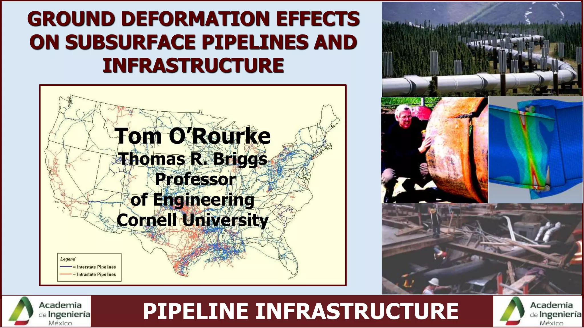
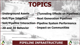
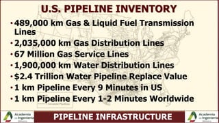
This document discusses pipeline infrastructure and soil-pipeline interaction. It covers several topics: underground assets and the large inventory of pipelines in the US and worldwide; the interface between soil and pipes; 2D and 3D modeling of soil-pipeline interaction; next generation hazard-resistant pipelines; and the impact of ground deformation on pipeline performance. The document provides examples of full-scale testing and numerical modeling to understand complex soil-pipeline behavior during different loading conditions.
Effect of Wind Direction through Double Storied Building Model Configurations...inventionjournals
: Effect of wind direction on plume dispersion around urban buildings has been investigated by physical modelling using arrays of buildings- like obstacles at scale 1:100 in boundary layer wind tunnel for double storied buildings and compared with field data. The particular effect of obstacle width- to - height ratio (S/H) was examined for a fixed obstacle plan area density. Series of experiments have been carried out in which the wind direction varied in steps of 5 for selected orientation of line source at 900 , 95, 100 and 105. Further, from the observation, it was concluded that the maximum lateral concentration shift to upward the wind direction of line source is increased for inline double storied buildings model configuration. It can be concluded, the wind tunnel results showed that concentrations at downwind distances decreased as the wind direction increases (positive values) for measured orientation of line source in inline double storied buildings model configuration. In comparison, experimentally observed σz values are below the field values. They were best fitted with power-law profiles. The non-dimensional concentration for both the field and wind tunnel results of double storied inline buildings configuration seems to be more or less uniform. Values of vertical spread parameters for double storied inline array configuration and field data were followed a similar trend but inline array configuration of double storied buildings model, non-dimensional concentrations were typically twice larger compared to the field data. This is attributed to the fact that the tracer material is quite concentrated in the recirculation region in inline array configuration of the double storied buildings model.
Abstract: Geo-technical engineering as a subject has developed considerably in the past four decades. There
has been remarkable development in the fields of design, research and construction of dam. India is capable of
designing and constructing a dam that would withstand a seismic jolt. The country needs water and electricity
to provide its people good living standards. Hydropower is the solution to the country's requirements, and this
can be achieved by storing water in dams.
In the past, earthquake effects may have been treated too lightly in dam design. Are such dams safe,
and how have they fared in previous earthquakes, this Paper will be limited to the some of finding about one
concrete types.
What will happen to dams during severe earthquake shaking? It is obvious that at present engineers
cannot answer this question with any certainty. But we are very much aware of the threat of disastrous losses of
life and damage to property if dams should fail, and we are making great effort to increase our under standing
of this complex topic.
This Paper deals with the case study of totaladoh Dam Situated in Vidarbha Region of Maharashtra
for Seismic Analysis by I.S.Code method (Simple Beam Analysis method). This also includes future scope of
analyzing the same dam for Seismic safety by very accurate method i.e. finite element method.
Keywords: Earthquake, The finite element method, Indian Standard codes(I.S.Code), horizontal
seismic coefficient (αh ),Hydrostatic pressure, Seismic analysis,
Pilot Tube Guided Boring Solutions Meet Project ChallengesLaura Anderson
Pilot tube guided boring equips contractors with the ability to accurately tackle extended trenchless gravity flow pipeline installations of 4-48-in. diameter pipe and larger with the guided auger boring method, in soft ground up to rock geology within a minimal footprint. Guided auger boring has positively impacted the auger boring market by ensuring bore accuracy, expediting installations, facilitating longer lengths, and reducing casing diameters for project savings. Pilot tube rock drilling has achieved success in rock density up to 12,000 psi using cutting tools to establish an accurate course for subsequent upsizing tooling. This presentation will explain these methods along with relevant case studies illustrating guided boring solutions that resolved project challenges.
C'est avec plaisir que nous partageons la présentation de M. Masood Meidani de l'Université McGill, lauréat du concours Branko Ladanyi pour ses travaux sur l'effort axial dans les conduites enfouies.
Il remporte une bourse qui lui permettra d’assister à la 71e Conférence Canadienne de Géotechnique qui se tiendra à Edmonton du 23 au 26 septembre 2018 (http://www.geoedmonton2018.ca).
Ce prix a été nommé en l'honneur de M. Branko Ladanyi, Professeur émérite à l'École Polytechnique de Montréal. Durant sa longue et fructueuse carrière, le Professeur Ladanyi a enseigné la géotechnique et mené des travaux de recherche originaux sur une variété de sujets, incluant le comportement des sables, des argiles et des roches, et le dimensionnement des fondations superficielles et profondes. Il est à l’origine de nombreuses contributions scientifiques et techniques marquantes qui sont présentées à travers plus de 200 publications. Il s'est avéré un pionnier dans le domaine de la géotechnique des sols gelés et de l'ingénierie en régions froides. Il est l'auteur, avec O.B. Andersland, du « best-seller » intitulé « An Introduction to Frozen Ground Engineering » (Chapman & Hall, 1994; Second Edition, ASCE Press et John Wiley & Sons, 2003). Ces travaux ont valu au Professeur Ladanyi une grande renommée internationale et de nombreux prix prestigieux. Il est membre de l'Académie canadienne du génie et de l'Académie des sciences de la Société royale du Canada.
Applicatio of Soil Structure Interaction in the analysis of flexible retainin...NikhilGautam68
Analysis and study of Soil Structure Interaction (ssi) in retaining wall. This presentation will help you in understanding the role of SSI in the making of a retaining wall which also expands the opportunity of research to great extent.
The main objectives are as follows:
1. To analyse the deformation of the structural system based on mobilised earth pressure and soil resistance along the wall.
2. To use non linear p-y curve for modelling the passive resistance of soils due to lateral deformation of embedded wall section.
3. To analyse group affect on pile
Hope it helps.
Flow Investigation inside A Curved Square DuctIJERA Editor
This paper presents the results of an experimental work with measurement of wall static pressure of 90°C shaped Curved duct. The test duct is made up of transparent perspex sheets to facilitate the flow visualization study. The duct has an inlet to exit area ratio of 1.0 with centerline distance of 750 mm. The inlet aspect ratio of the test duct has been fixed at 1.0. The velocities for the proposed investigations are to be measured by using a Pitot tube.Wall pressures are measured with the help of an inclinedmanometer with the inclination of 35°. The manometer had two tubes emanating from it: one left open to the atmosphere and the other connected to the steel pipes attached to the four walls of the curved duct. The difference in the readings helped us calculate the static pressure and thereby the normalized pressure. Wall pressure distribution along the curved and parallel walls of the duct at 0°, 22.5°, 45°, 67.5° and 90° measuring sections was measured. All the experimental data has been processed by an Intel i3 CPU, 3 GB RAM PC and analyzed to give the distribution of static pressure in the square duct.The main purpose of this investigation is to show the development of secondary flow which happens when the flow takes place through the bend in the curvature. This secondary flow arises as a result of a centrifugal force acting when the flow moves through the bend. The investigation is carried out at three different velocities 20 m/s, 40 m/s and 60 m/s. The distribution of normalized pressure which is the ratio of static pressure to the dynamic pressure is mapped and shown in the form of contours by using the software package SURFER.The trend of wall static pressure development on the walls of C shaped duct shows that as the flow proceeds towards the curvature, there exists a high pressure gradient between the outside face and inside face due the centrifugal force acting along the curvature. This shows the bulk shifting of flow towards the inside face. This is due to the generation of secondary motion in a plane perpendicular to the primary flow.
A Computational Investigation of Flow Structure Within a Sinuous DuctIJERA Editor
In the present investigation the distribution of mean velocity are experimentally studied on three constant area
rectangular curved ducts with an aspect ratio of 2.4. First one is C-shape, second one is S-shape and third one
is a DS-shape duct. The experiment is carried out at mass averaged mean velocity of 40m/s for all the ducts.
The velocity distribution shows for C-duct, the bulk flow shifting from outer wall to the inner wall along the
flow passage and for S-duct, the bulk flow shifting from outer wall to the inner wall in the first half and from
inner wall to the outer wall in the second half along the flow passage of curved ducts are very instinct. Due to
the imbalance of centrifugal force and radial pressure gradient, secondary motions in the forms of counter
rotating vortices have been generated within both the curved duct. For DS-duct the velocity distributions shows
the Bulk of flow shifting from inner watt to outer wall in the first bend and third bend of the duct and outer wall
to inner wall in the second bend and forth bend of the duct along the flow passage is very instinct. Flow at end
of the DS-duct is purely uniform in nature due to non existence of secondary motion. The experimental results
then were numerically validated with the help of Fluent, which shows a good agreement between the
experimental and predicted results for all the ducts
Welcome to WIPAC Monthly the magazine brought to you by the LinkedIn Group Water Industry Process Automation & Control.
In this month's edition, along with this month's industry news to celebrate the 13 years since the group was created we have articles including
A case study of the used of Advanced Process Control at the Wastewater Treatment works at Lleida in Spain
A look back on an article on smart wastewater networks in order to see how the industry has measured up in the interim around the adoption of Digital Transformation in the Water Industry.
Cosmetic shop management system project report.pdfKamal Acharya
Buying new cosmetic products is difficult. It can even be scary for those who have sensitive skin and are prone to skin trouble. The information needed to alleviate this problem is on the back of each product, but it's thought to interpret those ingredient lists unless you have a background in chemistry.
Instead of buying and hoping for the best, we can use data science to help us predict which products may be good fits for us. It includes various function programs to do the above mentioned tasks.
Data file handling has been effectively used in the program.
The automated cosmetic shop management system should deal with the automation of general workflow and administration process of the shop. The main processes of the system focus on customer's request where the system is able to search the most appropriate products and deliver it to the customers. It should help the employees to quickly identify the list of cosmetic product that have reached the minimum quantity and also keep a track of expired date for each cosmetic product. It should help the employees to find the rack number in which the product is placed.It is also Faster and more efficient way.
CFD Simulation of By-pass Flow in a HRSG module by R&R Consult.pptxR&R Consult
CFD analysis is incredibly effective at solving mysteries and improving the performance of complex systems!
Here's a great example: At a large natural gas-fired power plant, where they use waste heat to generate steam and energy, they were puzzled that their boiler wasn't producing as much steam as expected.
R&R and Tetra Engineering Group Inc. were asked to solve the issue with reduced steam production.
An inspection had shown that a significant amount of hot flue gas was bypassing the boiler tubes, where the heat was supposed to be transferred.
R&R Consult conducted a CFD analysis, which revealed that 6.3% of the flue gas was bypassing the boiler tubes without transferring heat. The analysis also showed that the flue gas was instead being directed along the sides of the boiler and between the modules that were supposed to capture the heat. This was the cause of the reduced performance.
Based on our results, Tetra Engineering installed covering plates to reduce the bypass flow. This improved the boiler's performance and increased electricity production.
It is always satisfying when we can help solve complex challenges like this. Do your systems also need a check-up or optimization? Give us a call!
Work done in cooperation with James Malloy and David Moelling from Tetra Engineering.
More examples of our work https://www.r-r-consult.dk/en/cases-en/
Overview of the fundamental roles in Hydropower generation and the components involved in wider Electrical Engineering.
This paper presents the design and construction of hydroelectric dams from the hydrologist’s survey of the valley before construction, all aspects and involved disciplines, fluid dynamics, structural engineering, generation and mains frequency regulation to the very transmission of power through the network in the United Kingdom.
Author: Robbie Edward Sayers
Collaborators and co editors: Charlie Sims and Connor Healey.
(C) 2024 Robbie E. Sayers
Industrial Training at Shahjalal Fertilizer Company Limited (SFCL)MdTanvirMahtab2
This presentation is about the working procedure of Shahjalal Fertilizer Company Limited (SFCL). A Govt. owned Company of Bangladesh Chemical Industries Corporation under Ministry of Industries.
About
Indigenized remote control interface card suitable for MAFI system CCR equipment. Compatible for IDM8000 CCR. Backplane mounted serial and TCP/Ethernet communication module for CCR remote access. IDM 8000 CCR remote control on serial and TCP protocol.
• Remote control: Parallel or serial interface.
• Compatible with MAFI CCR system.
• Compatible with IDM8000 CCR.
• Compatible with Backplane mount serial communication.
• Compatible with commercial and Defence aviation CCR system.
• Remote control system for accessing CCR and allied system over serial or TCP.
• Indigenized local Support/presence in India.
• Easy in configuration using DIP switches.
Technical Specifications
Indigenized remote control interface card suitable for MAFI system CCR equipment. Compatible for IDM8000 CCR. Backplane mounted serial and TCP/Ethernet communication module for CCR remote access. IDM 8000 CCR remote control on serial and TCP protocol.
Key Features
Indigenized remote control interface card suitable for MAFI system CCR equipment. Compatible for IDM8000 CCR. Backplane mounted serial and TCP/Ethernet communication module for CCR remote access. IDM 8000 CCR remote control on serial and TCP protocol.
• Remote control: Parallel or serial interface
• Compatible with MAFI CCR system
• Copatiable with IDM8000 CCR
• Compatible with Backplane mount serial communication.
• Compatible with commercial and Defence aviation CCR system.
• Remote control system for accessing CCR and allied system over serial or TCP.
• Indigenized local Support/presence in India.
Application
• Remote control: Parallel or serial interface.
• Compatible with MAFI CCR system.
• Compatible with IDM8000 CCR.
• Compatible with Backplane mount serial communication.
• Compatible with commercial and Defence aviation CCR system.
• Remote control system for accessing CCR and allied system over serial or TCP.
• Indigenized local Support/presence in India.
• Easy in configuration using DIP switches.
Saudi Arabia stands as a titan in the global energy landscape, renowned for its abundant oil and gas resources. It's the largest exporter of petroleum and holds some of the world's most significant reserves. Let's delve into the top 10 oil and gas projects shaping Saudi Arabia's energy future in 2024.
TECHNICAL TRAINING MANUAL GENERAL FAMILIARIZATION COURSEDuvanRamosGarzon1
AIRCRAFT GENERAL
The Single Aisle is the most advanced family aircraft in service today, with fly-by-wire flight controls.
The A318, A319, A320 and A321 are twin-engine subsonic medium range aircraft.
The family offers a choice of engines
NO1 Uk best vashikaran specialist in delhi vashikaran baba near me online vas...Amil Baba Dawood bangali
Contact with Dawood Bhai Just call on +92322-6382012 and we'll help you. We'll solve all your problems within 12 to 24 hours and with 101% guarantee and with astrology systematic. If you want to take any personal or professional advice then also you can call us on +92322-6382012 , ONLINE LOVE PROBLEM & Other all types of Daily Life Problem's.Then CALL or WHATSAPP us on +92322-6382012 and Get all these problems solutions here by Amil Baba DAWOOD BANGALI
#vashikaranspecialist #astrologer #palmistry #amliyaat #taweez #manpasandshadi #horoscope #spiritual #lovelife #lovespell #marriagespell#aamilbabainpakistan #amilbabainkarachi #powerfullblackmagicspell #kalajadumantarspecialist #realamilbaba #AmilbabainPakistan #astrologerincanada #astrologerindubai #lovespellsmaster #kalajaduspecialist #lovespellsthatwork #aamilbabainlahore#blackmagicformarriage #aamilbaba #kalajadu #kalailam #taweez #wazifaexpert #jadumantar #vashikaranspecialist #astrologer #palmistry #amliyaat #taweez #manpasandshadi #horoscope #spiritual #lovelife #lovespell #marriagespell#aamilbabainpakistan #amilbabainkarachi #powerfullblackmagicspell #kalajadumantarspecialist #realamilbaba #AmilbabainPakistan #astrologerincanada #astrologerindubai #lovespellsmaster #kalajaduspecialist #lovespellsthatwork #aamilbabainlahore #blackmagicforlove #blackmagicformarriage #aamilbaba #kalajadu #kalailam #taweez #wazifaexpert #jadumantar #vashikaranspecialist #astrologer #palmistry #amliyaat #taweez #manpasandshadi #horoscope #spiritual #lovelife #lovespell #marriagespell#aamilbabainpakistan #amilbabainkarachi #powerfullblackmagicspell #kalajadumantarspecialist #realamilbaba #AmilbabainPakistan #astrologerincanada #astrologerindubai #lovespellsmaster #kalajaduspecialist #lovespellsthatwork #aamilbabainlahore #Amilbabainuk #amilbabainspain #amilbabaindubai #Amilbabainnorway #amilbabainkrachi #amilbabainlahore #amilbabaingujranwalan #amilbabainislamabad
COLLEGE BUS MANAGEMENT SYSTEM PROJECT REPORT.pdfKamal Acharya
The College Bus Management system is completely developed by Visual Basic .NET Version. The application is connect with most secured database language MS SQL Server. The application is develop by using best combination of front-end and back-end languages. The application is totally design like flat user interface. This flat user interface is more attractive user interface in 2017. The application is gives more important to the system functionality. The application is to manage the student’s details, driver’s details, bus details, bus route details, bus fees details and more. The application has only one unit for admin. The admin can manage the entire application. The admin can login into the application by using username and password of the admin. The application is develop for big and small colleges. It is more user friendly for non-computer person. Even they can easily learn how to manage the application within hours. The application is more secure by the admin. The system will give an effective output for the VB.Net and SQL Server given as input to the system. The compiled java program given as input to the system, after scanning the program will generate different reports. The application generates the report for users. The admin can view and download the report of the data. The application deliver the excel format reports. Because, excel formatted reports is very easy to understand the income and expense of the college bus. This application is mainly develop for windows operating system users. In 2017, 73% of people enterprises are using windows operating system. So the application will easily install for all the windows operating system users. The application-developed size is very low. The application consumes very low space in disk. Therefore, the user can allocate very minimum local disk space for this application.
Vaccine management system project report documentation..pdfKamal Acharya
The Division of Vaccine and Immunization is facing increasing difficulty monitoring vaccines and other commodities distribution once they have been distributed from the national stores. With the introduction of new vaccines, more challenges have been anticipated with this additions posing serious threat to the already over strained vaccine supply chain system in Kenya.
5. PIPELINE INFRASTRUCTURE
U.S. PIPELINE INVENTORY
•489,000 km Gas & Liquid Fuel Transmission
Lines
•2,035,000 km Gas Distribution Lines
•67 Million Gas Service Lines
•1,900,000 km Water Distribution Lines
•$2.4 Trillion Water Pipeline Replace Value
•1 km Pipeline Every 9 Minutes in US
•1 km Pipeline Every 1-2 Minutes Worldwide
18. PIPELINE INFRASTRUCTURE
pmax
b) Normal Stress Distribution
τ
a) Shear Stress Orientation
θ
Expanded
View
O
θ
O
R=D/2
p(θ)
τ(θ)
dS=Rd
c) Expanded View
Note:Not in scale
dθ
pH
19. PIPELINE INFRASTRUCTURE
0 100 200
Normal Stress, kPa
= 10 mm
0 100 200
Normal Stress, kPa
= 30 mm
0 100 200
Normal Stress, kPa
= 120 mm
0 100 200
Normal Stress, kPa
= 10 mm
0 100 200
Normal Stress, kPa
= 30 mm
0 100 200
Normal Stress, kPa
= 120 mm
b) Centerline Sensor
a) Side Sensor
24. PIPELINE INFRASTRUCTURE
COUPLED TRANSVERSE & LONGITUDINAL SOIL FORCES
Gap Element:
Links Forces
Normal with
Forces Parallel
to Pipe By
Coulomb
Friction Law
tanT Nf p
25. PIPELINE INFRASTRUCTURE
LESSONS: SOIL-PIPE INTERFACE
•Relationship Between Soil Force Normal to Pipe
Surface vs Force Normal to Pipe Longitudinal
Axis Is Key for Modeling Coupled Soil-Pipe
Interaction
•Evaluation of Friction Along Pipe from Soil
Force Normal to Longitudinal Axis.
29. PIPELINE INFRASTRUCTURE
Pole for
planes
(’yy, ’yx)
(’xx, ’xy)
’ds
’ps
’
’
(0, dxy/2)
(dyy, dyx/2)
Pole for
directions
d
d/2
CO
Mohr’s circle for incremental strain
(’ff, ’ff)
Mohr’s circle for stress
(After Lings and Dietz, 2004)
Pole for
planes
(’yy, ’yx)
(’xx, ’xy)
’ds
’ps
’
’
(0, dxy/2)
(dyy, dyx/2)
Pole for
directions
d
d/2
CO
Mohr’s circle for incremental strain
(’ff, ’ff)
Mohr’s circle for stress
(After Lings and Dietz, 2004)
ψψ ψψ
Pole for
planes
(’yy, ’yx)
(’xx, ’xy)
’ds
’ps
’
’
(0, dxy/2)
(dyy, dyx/2)
Pole for
directions
d
d/2
CO
Mohr’s circle for incremental strain
(’ff, ’ff)
Mohr’s circle for stress
(After Lings and Dietz, 2004)
Pole for
planes
(’yy, ’yx)
(’xx, ’xy)
’ds
’ps
’
’
(0, dxy/2)
(dyy, dyx/2)
Pole for
directions
d
d/2
CO
Mohr’s circle for incremental strain
(’ff, ’ff)
Mohr’s circle for stress
(After Lings and Dietz, 2004)
ψψ ψψψψ ψψ
Direct Shear
Plane Strain
PLANE STRAIN & DIRECT SHEAR STRENGTH
42. PIPELINE INFRASTRUCTURE
SUCTION IN PARTIALLY SATURATED SOILS
Transpiration
Precipitation
Evaporation
Unsaturated Flow
Infiltration
Pipeline
Water table
Pores filled with
water
Meniscus formed
between particles
(After Robert et al, 2016)
48. PIPELINE INFRASTRUCTURE
LESSONS: SOIL-PIPELINE INTERACTION
• Integrated Methodology for Soil-Pipe
Interaction for All Pipe Movement Directions
and Depths: Hc/D ≥ 2
• Simulations Show Vertical Downward Soil/Pipe
Reaction Force ~ ½ to 1/3 Conventional
Bearing Capacity Force
• Suction-Enhanced Soil-Pipe Force
50. PIPELINE INFRASTRUCTURE
3D SOIL-PIPELINE INTERACTION
• Steel, HDPE and Cast
Iron
• Frequently Used D/t s
• D/L = 10
L
D
Apply Max Lateral Soil-Pipe Pressure to Simply Supported 3D Pipe (Shell) as
Proxy to Detect Transverse Distortion
D/t = 96
D = 900 mm
61. PIPELINE INFRASTRUCTURE
LESSONS: NEXT GENERATION (HAZARD-
RESILIENT) PIPELINES
•Paradigm Shift in Pipeline Technology
•Market-Driven Research Funded by
Industry
•Can’t Have Resilience Unless You Have a
Market
•Next Generation Hazard-Resilient Pipeline
Simulation Models
62. PIPELINE INFRASTRUCTURE
ADVANCED SENSORS
• Collaboration Among University of Cambridge,
Cornell, and UC Berkeley
• Demonstrate Proof of Concept
• Distributed Fiber Optics
• Joint Movement
• Pipeline Bending Strains & Displacement
• Time Domain Reflectometry
• Leakage
• Underground Wireless
• Data Transmission Without Wires
63. PIPELINE INFRASTRUCTURE
LESSONS: NEXT GENERATION (HAZARD-
RESILIENT) PIPELINES
•Paradigm Shift in Pipeline Technology
•Market-Driven Research Funded by
Industry
•Can’t Have Resilience Unless You Have a
Intelligence
•Next Generation Hazard-Resilient Pipeline
Simulation Models
73. PIPELINE INFRASTRUCTURE
SCREENING CRITERIA
• Repair Locations Checked by GIS
• Discount Landslides/Rockfall Areas
• Assume Poisson Distribution for Repairs
( ) (1p RR x p
Poisson distribution: μ = (RR)x, and σ = [(RR)x]½
Sampled repairs follow normal distr. (central limit theorem)
1
1 2 2
c
c
p
x RR
74. PIPELINE INFRASTRUCTURE
MAXIMUM PRINCIPAL LATERAL STRAIN
• Create Bilinear
Quadrilateral
Finite Element
from Lateral
Displacements
at Grid Corners
to Determine
Principal Strain
y, v
x, u
1 2
34
u1 u2
u4 u3
v2v1
v4 v3
75. PIPELINE INFRASTRUCTURE
REPAIR RATE VS ANGULAR DISTORTION AND LATERAL STRAIN
r2 = 0.86
r2 = 0.79
r2 = 0.88
Angular
Distortion
on 5-m
Spacing
Lateral
Strain
From
4 m x 4m
Cells
76. PIPELINE INFRASTRUCTURE
REPAIR RATE FOR COMBINED ANGULAR DISTORTION
AND LATERAL STRAINAsbestos Cement (AC) Pipelines
Cast Iron (CI) Pipelines
79. PIPELINE INFRASTRUCTURE
LESSONS FROM CHRISTCHURCH
• Extraordinary dataset: multiple EQs, dense ground
motion array, massive liquefaction, high density
LiDAR, geocoded repairs for thousands of km of
different pipelines
• First time comprehensive assessment of
underground lifeline response to liquefaction-
induced differential vertical movement and lateral
strain
• Unified methodology for building & lifeline damage
vs differential vertical & lateral ground movements
83. PIPELINE INFRASTRUCTURE
SAN FRANCISCO AUXILLIARY WATER SUPPLY
PERFORMANCE CRITERIA
•7.8 Mw
Deterministic EQ
•Water Demands in
Fire Response
Areas
•Monte Carlo AWSS
Network
Simulations
84. PIPELINE INFRASTRUCTURE
SUMMARY
• Coupled Soil-Pipe Forces for Soil-Pipeline Analysis
• Link Between Lateral Soil-Pipe Force and Pipe
Surface Frictional Resistance
• Methodology for Soil-Pipe Interaction in Granular Soil
for Any Pipe Movement Direction and Depth
• Vertical Downward Pipe Force Significantly Less Than
Conventional Bearing Capacity
• Soil Suction Effects
85. PIPELINE INFRASTRUCTURE
SUMMARY
• Guidance on Beam vs Shell Analysis for Soil-Pipe
Interaction. Transverse Distortion Important for
Diameters > 600 mm (Steel and Cast Iron)
• Next Generation Hazard Resilient Pipelines
• Canterbury EQ Sequence As Large-Scale Lab for
Characterizing Liquefaction Ground Deformation
• Unified Methodology for Pipeline and Building
Response to Soil Settlement and Lat’l. Displacement
• Impact on Communities