SlideShare a Scribd company logo
1 of 21
Transmission Media
Guided

Unguided

Guided Transmission Media
• Uses “Cabling” system
•The data signals are bound by the "cabling" system
• Also known as Bound Media.

Types of Guided Media
Open Wire

Twisted Pair

Coaxial Cable

Optical Fibre
Open Wire
There is a single wire strung between poles
No shielding or protection from noise interference is used.

This media is susceptible to a large degree of noise and
interference
Not acceptable for data transmission except for short
distances under 20 ft
Twisted Pair
The wires in Twisted Pair cabling are twisted together in pairs.
Each pair would consist of a wire used for the +ve data signal and a
wire used for the -ve data signal.
Any noise that appears on 1 wire of the pair would occur on the
other wire
Because the wires are opposite polarities, When the noise appears
on both wires, it cancels or nulls itself out at the receiving end.
The degree of reduction in noise interference is determined
specifically by the number of turns per foot.

Increasing the number of turns per foot reduces the noise
interference
To further improve noise rejection, a foil or wire braid shield is
woven around the twisted pairs
This "shield" can be woven around individual pairs or around a
multi-pair conductor (several pairs).
Twisted Pair
UTP
(Unshielded Twisted Pair)

STP
(Shielded Twisted Pair)

Twisting the wires together results in a characteristic impedance for the cable.
A typical impedance for UTP is 100 ohm for Ethernet 10BaseT cable.
UTP or Unshielded Twisted Pair cable is used on Ethernet 10BaseT and can also
be used with Token Ring.
It uses the RJ line of connectors (RJ45, RJ11, etc..)

STP or Shielded Twisted Pair is used with the traditional Token Ring cabling
Coaxial Cable
Coaxial Cable consists of 2 conductors
The inner conductor is held inside an insulator
The outer conductor woven around it providing a shield
An insulating protective coating called a jacket covers the outer
conductor.
The outer shield protects the inner conductor from outside electrical signals
The distance between the outer conductor (shield) and inner conductor plus
the type of material used for insulating the inner conductor determine the
cable properties or impedance.

Typical impedances for coaxial cables are 75 ohms for Cable TV, 50 ohms for
Ethernet Thinnet and Thicknet.
The excellent control of the impedance characteristics of the cable allow higher
data rates to be transferred than Twisted Pair cable.
Optical Fibre
Optical Fibre consists of thin glass fibres that can carry information
at frequencies in the visible light spectrum and beyond.

The typical optical fiber consists of a very narrow strand of glass
called the Core.
Around the Core is a concentric layer of glass called the Cladding. A
typical Core diameter is 62.5 microns (1 micron = 10-6 meters).
Typically Cladding has a diameter of 125 microns. Coating the
cladding is a protective coating consisting of plastic, it is called the
Jacket
Advantages of Optical Fiber
•Noise immunity: RFI and EMI immune (RFI - Radio Frequency Interference, EMI ElectroMagnetic Interference)
•Security: cannot tap into cable.
•Large Capacity due to BW (bandwidth)
•Longer distances than copper wire
•Smaller and lighter than copper wire
•Faster transmission rate
Refraction
An important characteristic of Fibre Optics is Refraction
Refraction is the characteristic of a material to either pass or reflect light.
When light passes through a medium, it "bends" as it passes from one medium to
the other.
If the angle of incidence is small, the light rays are reflected and do not pass
into the water
If the angle of incident is great, light passes through the media but is bent or
refracted.

Optical Fibres work on the principle that -

The core refracts the light
The cladding reflects the light.
The core refracts the light and guides the light along its path.
The cladding reflects any light back into the core and stops light from escaping
through it - it bounds the media

Optical Transmission Modes
There are 3 primary types of transmission modes using optical fibre.

a) Step Index
b) Grade Index
c) Single Mode
Step Index
Step Index has a large core. the light rays tend to bounce around, reflecting off the
cladding, inside the core.

This causes some rays to take a longer or shorted path through the core. Some take
the direct path with hardly any reflections while others bounce back and forth
taking a longer path.

The result is that the light rays arrive at the receiver at different times. The signal
becomes longer than the original signal.
Grade Index
Grade Index has a gradual change in the Core's Refractive Index.
This causes the light rays to be gradually bent back into the core path.
The result is a better receive signal than Step Index. LED light sources
are used. Typical Core: 62.5 microns.

Note: Both Step Index and Graded Index allow more than one light source
to be used (different colours simultaneously!). Multiple channels of data
can be run simultaneously!
Single Mode
Single Mode has separate distinct Refractive Indexes for the cladding and core.
The light ray passes through the core with relatively few reflections off the cladding.

Single Mode is used for a single source of light (one colour) operation.
It requires a laser and the core is very small: 9 microns
Disadvantages of Optical Fibre:
•Physical vibration will show up as signal noise!
•Limited physical arc of cable. Bend it too much & it will break!

•Difficult to splice

The cost of optical fiber is a trade-off between capacity and cost.-

- At higher transmission capacity, it is cheaper than copper.
- At lower transmission capacity, it is more expensive.
Transmission Media

Guided

Unguided

Guided Transmission Media
• Uses “Cabling” system
•The data signals are bound by the "cabling" system
• Also known as Bound Media.

Types of Guided Media
Open Wire

Twisted Pair

Coaxial Cable

Optical Fibre
Un-Guided Media
Wire less Media

Signals are transmitted in the form of Electro Magnetic waves
Waves ranges from 3KHz to 900 THz
Radio Waves & Micro waves

Infra Red

300 GHz

3 KHz

Light Waves

400 THz

900 THz

Classification of Un-Guided Media
On the basis of Band

On the basis of Propagation Method

Radio Waves

Ground

Micro waves

Sky

Infra Red

Line- of- Sight
Wireless Media
GROUND Propagation

SKY Propagation

(On the basis of Propagation Method)

Line- of- Sight propagation

Ionosphere
Earth
Earth
Earth

In ground PropagationThe Radio Waves transmitted
Through the lowest portion of
the atmosphere
Low Frequency Signals are used
The distance is depended on the
Power of the Signal

Higher Frequency Radio Waves

Very High Frequency Signals

Transmission through Ionosphere Transmitted in straight Lines
from antenna to antenna
Allow greater Distance
Antenna must be directional
and faced each other
Antenna should not be
affected by the curvature
of the earth
Electromagnetic medium is divided into Eight Ranges- called BANDS
Band

Range

Propagation

Application

VLF
(Very Low Frequency)

3-30 KHz

Ground

Long Range Radio
Navigation

LF
(Low Frequency)

30-300KHz

Ground

Radio Beacons and
Navigational Locators

MF
(Middle Frequency)

300KHz- 3 MHz

Sky

AM Radio

HF
(High Frequency)

3 MHz – 30 MHz

Sky

Citizen Band, Ship &
Air Craft
Communication

VHF
(Very High Frequency)

30 – 300 MHz

Sky & Line-of- Sight

VHF TV and FM Radio

UHF
300 MHz- 3 GHz
(Ultra High Frequency)

Line-of-Sight

UHF TV, Cellular
Phones

SHF
(Super High
Frequency)

3- 30 GHz

Line-of-Sight

Satellite
Communication

EHF
(Extremely High

30-300 GHz

Line-of-Sight

Radar/ Satellite
Transmission media

More Related Content

What's hot

Chapter 2 - Network Models
Chapter 2 - Network ModelsChapter 2 - Network Models
Chapter 2 - Network Models
Wayne Jones Jnr
 
3 handoff management
3 handoff management3 handoff management
3 handoff management
వం శీ
 
Microwave Transmission
Microwave TransmissionMicrowave Transmission
Microwave Transmission
Devang Bhatti
 
Cellular network
Cellular networkCellular network
Cellular network
shreb
 

What's hot (20)

IEEE 802.11 Architecture and Services
IEEE 802.11 Architecture and ServicesIEEE 802.11 Architecture and Services
IEEE 802.11 Architecture and Services
 
Wireless transmission
Wireless transmissionWireless transmission
Wireless transmission
 
Lan technologies
Lan technologiesLan technologies
Lan technologies
 
Computer Networks Unit 2 UNIT II DATA-LINK LAYER & MEDIA ACCESS
Computer Networks Unit 2 UNIT II DATA-LINK LAYER & MEDIA ACCESSComputer Networks Unit 2 UNIT II DATA-LINK LAYER & MEDIA ACCESS
Computer Networks Unit 2 UNIT II DATA-LINK LAYER & MEDIA ACCESS
 
Chapter 2 - Network Models
Chapter 2 - Network ModelsChapter 2 - Network Models
Chapter 2 - Network Models
 
Computer networks - Channelization
Computer networks - ChannelizationComputer networks - Channelization
Computer networks - Channelization
 
IEEE standards 802.3.&802.11
IEEE standards 802.3.&802.11IEEE standards 802.3.&802.11
IEEE standards 802.3.&802.11
 
WIRELESS TRANSMISSION MEDIA
WIRELESS  TRANSMISSION MEDIAWIRELESS  TRANSMISSION MEDIA
WIRELESS TRANSMISSION MEDIA
 
Transmission media
Transmission mediaTransmission media
Transmission media
 
3 handoff management
3 handoff management3 handoff management
3 handoff management
 
Wireless networking_ASRao
Wireless networking_ASRaoWireless networking_ASRao
Wireless networking_ASRao
 
It2402 mobile communication unit2
It2402 mobile communication unit2It2402 mobile communication unit2
It2402 mobile communication unit2
 
Guided Media
Guided MediaGuided Media
Guided Media
 
QOS (Quality of Services) - Computer Networks
 QOS (Quality of Services) - Computer Networks QOS (Quality of Services) - Computer Networks
QOS (Quality of Services) - Computer Networks
 
Microwave Transmission
Microwave TransmissionMicrowave Transmission
Microwave Transmission
 
Signaling system 7 (ss7)
Signaling system 7 (ss7)Signaling system 7 (ss7)
Signaling system 7 (ss7)
 
Quality of Service
Quality of ServiceQuality of Service
Quality of Service
 
Spread spectrum modulation
Spread spectrum modulationSpread spectrum modulation
Spread spectrum modulation
 
Cellular network
Cellular networkCellular network
Cellular network
 
Osi layer and network protocol
Osi layer and network protocolOsi layer and network protocol
Osi layer and network protocol
 

Viewers also liked

3. transmission media
3. transmission media3. transmission media
3. transmission media
Hattori Sidek
 
Behrouz forouzan -_transmision_de_datos_y_redes_de_comunicaciones
Behrouz forouzan -_transmision_de_datos_y_redes_de_comunicacionesBehrouz forouzan -_transmision_de_datos_y_redes_de_comunicaciones
Behrouz forouzan -_transmision_de_datos_y_redes_de_comunicaciones
edwinalb
 
Solution task first examen fula 2010
Solution task first examen   fula 2010Solution task first examen   fula 2010
Solution task first examen fula 2010
HernanFula
 
Mathematical modeling applied fula 2010
Mathematical modeling applied   fula 2010Mathematical modeling applied   fula 2010
Mathematical modeling applied fula 2010
HernanFula
 
Powerlinecarrier (3)
Powerlinecarrier (3)Powerlinecarrier (3)
Powerlinecarrier (3)
ajay901551
 
System Softwares
System SoftwaresSystem Softwares
System Softwares
nshnt_snghl
 
Network architecture
Network architectureNetwork architecture
Network architecture
linghazali
 
Transmission Media in Data Communication DC13
Transmission Media in Data Communication DC13Transmission Media in Data Communication DC13
Transmission Media in Data Communication DC13
koolkampus
 
Operating Systems
Operating SystemsOperating Systems
Operating Systems
Dan Hess
 

Viewers also liked (20)

Transmission Media, Guided and unguided transmission media
Transmission Media, Guided and unguided transmission mediaTransmission Media, Guided and unguided transmission media
Transmission Media, Guided and unguided transmission media
 
3. transmission media
3. transmission media3. transmission media
3. transmission media
 
Presentation on Transmission Media
Presentation on Transmission MediaPresentation on Transmission Media
Presentation on Transmission Media
 
Ppt for tranmission media
Ppt for tranmission mediaPpt for tranmission media
Ppt for tranmission media
 
Transmission media
Transmission mediaTransmission media
Transmission media
 
Behrouz forouzan -_transmision_de_datos_y_redes_de_comunicaciones
Behrouz forouzan -_transmision_de_datos_y_redes_de_comunicacionesBehrouz forouzan -_transmision_de_datos_y_redes_de_comunicaciones
Behrouz forouzan -_transmision_de_datos_y_redes_de_comunicaciones
 
Solution task first examen fula 2010
Solution task first examen   fula 2010Solution task first examen   fula 2010
Solution task first examen fula 2010
 
Mathematical modeling applied fula 2010
Mathematical modeling applied   fula 2010Mathematical modeling applied   fula 2010
Mathematical modeling applied fula 2010
 
Powerlinecarrier (3)
Powerlinecarrier (3)Powerlinecarrier (3)
Powerlinecarrier (3)
 
Computer network
Computer networkComputer network
Computer network
 
Transmission media
Transmission  mediaTransmission  media
Transmission media
 
Application softwares
Application softwaresApplication softwares
Application softwares
 
System Softwares
System SoftwaresSystem Softwares
System Softwares
 
Voip
VoipVoip
Voip
 
Asynchronous Microservices in nodejs
Asynchronous Microservices in nodejsAsynchronous Microservices in nodejs
Asynchronous Microservices in nodejs
 
Network architecture
Network architectureNetwork architecture
Network architecture
 
Transmission Media in Data Communication DC13
Transmission Media in Data Communication DC13Transmission Media in Data Communication DC13
Transmission Media in Data Communication DC13
 
Operating Systems
Operating SystemsOperating Systems
Operating Systems
 
Operating System Overview.
Operating System Overview.Operating System Overview.
Operating System Overview.
 
FAULT ANALYSIS OF HVDC TRANSMISSION SYSTEMS
FAULT ANALYSIS OF HVDC TRANSMISSION SYSTEMSFAULT ANALYSIS OF HVDC TRANSMISSION SYSTEMS
FAULT ANALYSIS OF HVDC TRANSMISSION SYSTEMS
 

Similar to Transmission media

Optical fibre cable
Optical fibre cableOptical fibre cable
Optical fibre cable
Aman Agarwal
 
Optical fiber communiction
Optical fiber communictionOptical fiber communiction
Optical fiber communiction
Aravind Shaji
 
Dcunit4 transmission media
Dcunit4 transmission mediaDcunit4 transmission media
Dcunit4 transmission media
Akshay Nagpurkar
 
Fibre optics by alina ramla mahira.
Fibre optics by alina ramla mahira.Fibre optics by alina ramla mahira.
Fibre optics by alina ramla mahira.
Alina Baber
 

Similar to Transmission media (20)

Optical fiber
Optical fiberOptical fiber
Optical fiber
 
Cables &wire
Cables &wireCables &wire
Cables &wire
 
Rothmans
RothmansRothmans
Rothmans
 
Rothman
RothmanRothman
Rothman
 
Optical communications
Optical communicationsOptical communications
Optical communications
 
Unit_I - 4
Unit_I - 4Unit_I - 4
Unit_I - 4
 
Ofc introduction
Ofc introduction Ofc introduction
Ofc introduction
 
Optical fibre cable
Optical fibre cableOptical fibre cable
Optical fibre cable
 
optical fibers.pptx
optical fibers.pptxoptical fibers.pptx
optical fibers.pptx
 
Fiber optics
Fiber optics Fiber optics
Fiber optics
 
B.Tech ECE IV Year I Sem, MWOC UNIT 5 Optical CommunicationsUNIT 5 MWOC.pptx
B.Tech ECE IV Year I Sem, MWOC UNIT 5  Optical CommunicationsUNIT 5 MWOC.pptxB.Tech ECE IV Year I Sem, MWOC UNIT 5  Optical CommunicationsUNIT 5 MWOC.pptx
B.Tech ECE IV Year I Sem, MWOC UNIT 5 Optical CommunicationsUNIT 5 MWOC.pptx
 
Unit 3 _CND_22634_ physical layer_transmission medium_pranoti doke
Unit 3 _CND_22634_ physical layer_transmission medium_pranoti dokeUnit 3 _CND_22634_ physical layer_transmission medium_pranoti doke
Unit 3 _CND_22634_ physical layer_transmission medium_pranoti doke
 
Optical fiber communiction
Optical fiber communictionOptical fiber communiction
Optical fiber communiction
 
FIBER OPTICS .ppt
FIBER OPTICS .pptFIBER OPTICS .ppt
FIBER OPTICS .ppt
 
Lecture3 Physical Layer
Lecture3 Physical LayerLecture3 Physical Layer
Lecture3 Physical Layer
 
Fiber optics
Fiber optics Fiber optics
Fiber optics
 
Dcunit4 transmission media
Dcunit4 transmission mediaDcunit4 transmission media
Dcunit4 transmission media
 
Assignment1 network media
Assignment1 network mediaAssignment1 network media
Assignment1 network media
 
Fibre optics by alina ramla mahira.
Fibre optics by alina ramla mahira.Fibre optics by alina ramla mahira.
Fibre optics by alina ramla mahira.
 
Optical fiber
Optical fiberOptical fiber
Optical fiber
 

More from jyoti_lakhani

Ds06 linked list- insert a node after a given node
Ds06   linked list-  insert a node after a given nodeDs06   linked list-  insert a node after a given node
Ds06 linked list- insert a node after a given node
jyoti_lakhani
 
Ds01 data structure introduction - by jyoti lakhani
Ds01 data structure  introduction - by jyoti lakhaniDs01 data structure  introduction - by jyoti lakhani
Ds01 data structure introduction - by jyoti lakhani
jyoti_lakhani
 

More from jyoti_lakhani (20)

CG02 Computer Graphic Systems.ppsx
CG02 Computer Graphic Systems.ppsxCG02 Computer Graphic Systems.ppsx
CG02 Computer Graphic Systems.ppsx
 
Projections.pptx
Projections.pptxProjections.pptx
Projections.pptx
 
CG04 Color Models.ppsx
CG04 Color Models.ppsxCG04 Color Models.ppsx
CG04 Color Models.ppsx
 
CG03 Random Raster Scan displays and Color CRTs.ppsx
CG03 Random Raster Scan displays and Color CRTs.ppsxCG03 Random Raster Scan displays and Color CRTs.ppsx
CG03 Random Raster Scan displays and Color CRTs.ppsx
 
CG02 Computer Graphic Systems.pptx
CG02 Computer Graphic Systems.pptxCG02 Computer Graphic Systems.pptx
CG02 Computer Graphic Systems.pptx
 
CG01 introduction.ppsx
CG01 introduction.ppsxCG01 introduction.ppsx
CG01 introduction.ppsx
 
Doubly linked list
Doubly linked listDoubly linked list
Doubly linked list
 
Double ended queue
Double ended queueDouble ended queue
Double ended queue
 
Tree terminology and introduction to binary tree
Tree terminology and introduction to binary treeTree terminology and introduction to binary tree
Tree terminology and introduction to binary tree
 
Priority queue
Priority queuePriority queue
Priority queue
 
Ds006 linked list- delete from front
Ds006   linked list- delete from frontDs006   linked list- delete from front
Ds006 linked list- delete from front
 
Ds06 linked list- insert a node after a given node
Ds06   linked list-  insert a node after a given nodeDs06   linked list-  insert a node after a given node
Ds06 linked list- insert a node after a given node
 
Ds06 linked list- insert a node at end
Ds06   linked list- insert a node at endDs06   linked list- insert a node at end
Ds06 linked list- insert a node at end
 
Ds06 linked list- insert a node at beginning
Ds06   linked list- insert a node at beginningDs06   linked list- insert a node at beginning
Ds06 linked list- insert a node at beginning
 
Ds06 linked list- intro and create a node
Ds06   linked list- intro and create a nodeDs06   linked list- intro and create a node
Ds06 linked list- intro and create a node
 
Ds04 abstract data types (adt) jyoti lakhani
Ds04 abstract data types (adt) jyoti lakhaniDs04 abstract data types (adt) jyoti lakhani
Ds04 abstract data types (adt) jyoti lakhani
 
Ds03 part i algorithms by jyoti lakhani
Ds03 part i algorithms   by jyoti lakhaniDs03 part i algorithms   by jyoti lakhani
Ds03 part i algorithms by jyoti lakhani
 
Ds03 algorithms jyoti lakhani
Ds03 algorithms jyoti lakhaniDs03 algorithms jyoti lakhani
Ds03 algorithms jyoti lakhani
 
Ds02 flow chart and pseudo code
Ds02 flow chart and pseudo codeDs02 flow chart and pseudo code
Ds02 flow chart and pseudo code
 
Ds01 data structure introduction - by jyoti lakhani
Ds01 data structure  introduction - by jyoti lakhaniDs01 data structure  introduction - by jyoti lakhani
Ds01 data structure introduction - by jyoti lakhani
 

Recently uploaded

Recently uploaded (20)

How to Give a Domain for a Field in Odoo 17
How to Give a Domain for a Field in Odoo 17How to Give a Domain for a Field in Odoo 17
How to Give a Domain for a Field in Odoo 17
 
PROCESS RECORDING FORMAT.docx
PROCESS      RECORDING        FORMAT.docxPROCESS      RECORDING        FORMAT.docx
PROCESS RECORDING FORMAT.docx
 
How to Create and Manage Wizard in Odoo 17
How to Create and Manage Wizard in Odoo 17How to Create and Manage Wizard in Odoo 17
How to Create and Manage Wizard in Odoo 17
 
microwave assisted reaction. General introduction
microwave assisted reaction. General introductionmicrowave assisted reaction. General introduction
microwave assisted reaction. General introduction
 
Python Notes for mca i year students osmania university.docx
Python Notes for mca i year students osmania university.docxPython Notes for mca i year students osmania university.docx
Python Notes for mca i year students osmania university.docx
 
Micro-Scholarship, What it is, How can it help me.pdf
Micro-Scholarship, What it is, How can it help me.pdfMicro-Scholarship, What it is, How can it help me.pdf
Micro-Scholarship, What it is, How can it help me.pdf
 
TỔNG ÔN TẬP THI VÀO LỚP 10 MÔN TIẾNG ANH NĂM HỌC 2023 - 2024 CÓ ĐÁP ÁN (NGỮ Â...
TỔNG ÔN TẬP THI VÀO LỚP 10 MÔN TIẾNG ANH NĂM HỌC 2023 - 2024 CÓ ĐÁP ÁN (NGỮ Â...TỔNG ÔN TẬP THI VÀO LỚP 10 MÔN TIẾNG ANH NĂM HỌC 2023 - 2024 CÓ ĐÁP ÁN (NGỮ Â...
TỔNG ÔN TẬP THI VÀO LỚP 10 MÔN TIẾNG ANH NĂM HỌC 2023 - 2024 CÓ ĐÁP ÁN (NGỮ Â...
 
Mixin Classes in Odoo 17 How to Extend Models Using Mixin Classes
Mixin Classes in Odoo 17  How to Extend Models Using Mixin ClassesMixin Classes in Odoo 17  How to Extend Models Using Mixin Classes
Mixin Classes in Odoo 17 How to Extend Models Using Mixin Classes
 
Spatium Project Simulation student brief
Spatium Project Simulation student briefSpatium Project Simulation student brief
Spatium Project Simulation student brief
 
Unit-V; Pricing (Pharma Marketing Management).pptx
Unit-V; Pricing (Pharma Marketing Management).pptxUnit-V; Pricing (Pharma Marketing Management).pptx
Unit-V; Pricing (Pharma Marketing Management).pptx
 
Understanding Accommodations and Modifications
Understanding  Accommodations and ModificationsUnderstanding  Accommodations and Modifications
Understanding Accommodations and Modifications
 
Unit-IV- Pharma. Marketing Channels.pptx
Unit-IV- Pharma. Marketing Channels.pptxUnit-IV- Pharma. Marketing Channels.pptx
Unit-IV- Pharma. Marketing Channels.pptx
 
ICT Role in 21st Century Education & its Challenges.pptx
ICT Role in 21st Century Education & its Challenges.pptxICT Role in 21st Century Education & its Challenges.pptx
ICT Role in 21st Century Education & its Challenges.pptx
 
Asian American Pacific Islander Month DDSD 2024.pptx
Asian American Pacific Islander Month DDSD 2024.pptxAsian American Pacific Islander Month DDSD 2024.pptx
Asian American Pacific Islander Month DDSD 2024.pptx
 
Mehran University Newsletter Vol-X, Issue-I, 2024
Mehran University Newsletter Vol-X, Issue-I, 2024Mehran University Newsletter Vol-X, Issue-I, 2024
Mehran University Newsletter Vol-X, Issue-I, 2024
 
SOC 101 Demonstration of Learning Presentation
SOC 101 Demonstration of Learning PresentationSOC 101 Demonstration of Learning Presentation
SOC 101 Demonstration of Learning Presentation
 
Third Battle of Panipat detailed notes.pptx
Third Battle of Panipat detailed notes.pptxThird Battle of Panipat detailed notes.pptx
Third Battle of Panipat detailed notes.pptx
 
Accessible Digital Futures project (20/03/2024)
Accessible Digital Futures project (20/03/2024)Accessible Digital Futures project (20/03/2024)
Accessible Digital Futures project (20/03/2024)
 
This PowerPoint helps students to consider the concept of infinity.
This PowerPoint helps students to consider the concept of infinity.This PowerPoint helps students to consider the concept of infinity.
This PowerPoint helps students to consider the concept of infinity.
 
UGC NET Paper 1 Mathematical Reasoning & Aptitude.pdf
UGC NET Paper 1 Mathematical Reasoning & Aptitude.pdfUGC NET Paper 1 Mathematical Reasoning & Aptitude.pdf
UGC NET Paper 1 Mathematical Reasoning & Aptitude.pdf
 

Transmission media

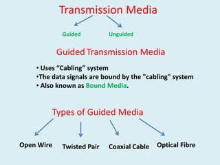
  • 1. Transmission Media Guided Unguided Guided Transmission Media • Uses “Cabling” system •The data signals are bound by the "cabling" system • Also known as Bound Media. Types of Guided Media Open Wire Twisted Pair Coaxial Cable Optical Fibre
  • 2. Open Wire There is a single wire strung between poles No shielding or protection from noise interference is used. This media is susceptible to a large degree of noise and interference Not acceptable for data transmission except for short distances under 20 ft
  • 3. Twisted Pair The wires in Twisted Pair cabling are twisted together in pairs. Each pair would consist of a wire used for the +ve data signal and a wire used for the -ve data signal. Any noise that appears on 1 wire of the pair would occur on the other wire Because the wires are opposite polarities, When the noise appears on both wires, it cancels or nulls itself out at the receiving end.
  • 4. The degree of reduction in noise interference is determined specifically by the number of turns per foot. Increasing the number of turns per foot reduces the noise interference To further improve noise rejection, a foil or wire braid shield is woven around the twisted pairs This "shield" can be woven around individual pairs or around a multi-pair conductor (several pairs).
  • 5. Twisted Pair UTP (Unshielded Twisted Pair) STP (Shielded Twisted Pair) Twisting the wires together results in a characteristic impedance for the cable. A typical impedance for UTP is 100 ohm for Ethernet 10BaseT cable. UTP or Unshielded Twisted Pair cable is used on Ethernet 10BaseT and can also be used with Token Ring. It uses the RJ line of connectors (RJ45, RJ11, etc..) STP or Shielded Twisted Pair is used with the traditional Token Ring cabling
  • 6. Coaxial Cable Coaxial Cable consists of 2 conductors The inner conductor is held inside an insulator The outer conductor woven around it providing a shield An insulating protective coating called a jacket covers the outer conductor. The outer shield protects the inner conductor from outside electrical signals
  • 7. The distance between the outer conductor (shield) and inner conductor plus the type of material used for insulating the inner conductor determine the cable properties or impedance. Typical impedances for coaxial cables are 75 ohms for Cable TV, 50 ohms for Ethernet Thinnet and Thicknet. The excellent control of the impedance characteristics of the cable allow higher data rates to be transferred than Twisted Pair cable.
  • 8. Optical Fibre Optical Fibre consists of thin glass fibres that can carry information at frequencies in the visible light spectrum and beyond. The typical optical fiber consists of a very narrow strand of glass called the Core. Around the Core is a concentric layer of glass called the Cladding. A typical Core diameter is 62.5 microns (1 micron = 10-6 meters). Typically Cladding has a diameter of 125 microns. Coating the cladding is a protective coating consisting of plastic, it is called the Jacket
  • 9. Advantages of Optical Fiber •Noise immunity: RFI and EMI immune (RFI - Radio Frequency Interference, EMI ElectroMagnetic Interference) •Security: cannot tap into cable. •Large Capacity due to BW (bandwidth) •Longer distances than copper wire •Smaller and lighter than copper wire •Faster transmission rate
  • 10. Refraction An important characteristic of Fibre Optics is Refraction Refraction is the characteristic of a material to either pass or reflect light. When light passes through a medium, it "bends" as it passes from one medium to the other.
  • 11. If the angle of incidence is small, the light rays are reflected and do not pass into the water If the angle of incident is great, light passes through the media but is bent or refracted. Optical Fibres work on the principle that - The core refracts the light The cladding reflects the light.
  • 12. The core refracts the light and guides the light along its path. The cladding reflects any light back into the core and stops light from escaping through it - it bounds the media Optical Transmission Modes There are 3 primary types of transmission modes using optical fibre. a) Step Index b) Grade Index c) Single Mode
  • 13. Step Index Step Index has a large core. the light rays tend to bounce around, reflecting off the cladding, inside the core. This causes some rays to take a longer or shorted path through the core. Some take the direct path with hardly any reflections while others bounce back and forth taking a longer path. The result is that the light rays arrive at the receiver at different times. The signal becomes longer than the original signal.
  • 14. Grade Index Grade Index has a gradual change in the Core's Refractive Index. This causes the light rays to be gradually bent back into the core path. The result is a better receive signal than Step Index. LED light sources are used. Typical Core: 62.5 microns. Note: Both Step Index and Graded Index allow more than one light source to be used (different colours simultaneously!). Multiple channels of data can be run simultaneously!
  • 15. Single Mode Single Mode has separate distinct Refractive Indexes for the cladding and core. The light ray passes through the core with relatively few reflections off the cladding. Single Mode is used for a single source of light (one colour) operation. It requires a laser and the core is very small: 9 microns
  • 16. Disadvantages of Optical Fibre: •Physical vibration will show up as signal noise! •Limited physical arc of cable. Bend it too much & it will break! •Difficult to splice The cost of optical fiber is a trade-off between capacity and cost.- - At higher transmission capacity, it is cheaper than copper. - At lower transmission capacity, it is more expensive.
  • 17. Transmission Media Guided Unguided Guided Transmission Media • Uses “Cabling” system •The data signals are bound by the "cabling" system • Also known as Bound Media. Types of Guided Media Open Wire Twisted Pair Coaxial Cable Optical Fibre
  • 18. Un-Guided Media Wire less Media Signals are transmitted in the form of Electro Magnetic waves Waves ranges from 3KHz to 900 THz Radio Waves & Micro waves Infra Red 300 GHz 3 KHz Light Waves 400 THz 900 THz Classification of Un-Guided Media On the basis of Band On the basis of Propagation Method Radio Waves Ground Micro waves Sky Infra Red Line- of- Sight
  • 19. Wireless Media GROUND Propagation SKY Propagation (On the basis of Propagation Method) Line- of- Sight propagation Ionosphere Earth Earth Earth In ground PropagationThe Radio Waves transmitted Through the lowest portion of the atmosphere Low Frequency Signals are used The distance is depended on the Power of the Signal Higher Frequency Radio Waves Very High Frequency Signals Transmission through Ionosphere Transmitted in straight Lines from antenna to antenna Allow greater Distance Antenna must be directional and faced each other Antenna should not be affected by the curvature of the earth
  • 20. Electromagnetic medium is divided into Eight Ranges- called BANDS Band Range Propagation Application VLF (Very Low Frequency) 3-30 KHz Ground Long Range Radio Navigation LF (Low Frequency) 30-300KHz Ground Radio Beacons and Navigational Locators MF (Middle Frequency) 300KHz- 3 MHz Sky AM Radio HF (High Frequency) 3 MHz – 30 MHz Sky Citizen Band, Ship & Air Craft Communication VHF (Very High Frequency) 30 – 300 MHz Sky & Line-of- Sight VHF TV and FM Radio UHF 300 MHz- 3 GHz (Ultra High Frequency) Line-of-Sight UHF TV, Cellular Phones SHF (Super High Frequency) 3- 30 GHz Line-of-Sight Satellite Communication EHF (Extremely High 30-300 GHz Line-of-Sight Radar/ Satellite