
Recommended
More Related Content
What's hot
What's hot (20)
Similar to X-RAY GENERATORS(1).pdf
Similar to X-RAY GENERATORS(1).pdf (20)
Recently uploaded
Recently uploaded (20)
X-RAY GENERATORS(1).pdf
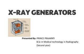
- 1. X-RAY GENERATORS Presented By- PRINCE PRAJAPATI B.Sc in Medical technology in Radiography (Second year)
- 2. CONSOLE TRANSFORMER ASSEMBLY X-RAY GENERATORS • Low voltage Transformer • High voltage Transformer High voltage rectifiers
- 3. CONSOLE
- 4. Transformer assembly • The transformer assembly is a grounded metal box fill with oil. • It contains the low voltage Transformer for the filament circuit and high voltage Transformer and group of rectifiers for the high voltage circuit.
- 5. TRANSFORMERS • A transformer is a device that either increases or decreases the voltage in a circuit. • Current only flows in the secondary circuit when the magnetic field is increasing or decreasing • When current flow through the primary coil it creates magnetic field in the core and this magnetic field induces a current in the secondary coil.
- 6. • The voltage in the two circuits is proportional to the number of turns in the coils. • A transformer can’t create energy, the power of primary circuit is equal to the secondary circuit. • Step up Transformer • Step down Transformer
- 8. The Autotransformer An Autotransformer consist of single winding wound on a laminated closed core. It works on the principle of self induction Function:- Provides voltage for the x-ray tube filament circuit and convenient location for kVp meter that measures voltage across the x- ray tube
- 9. Low voltage circuit • The filament circuit regulates current flow through the filament of x-ray tube. • The power to heat the filament provided by small step down transformer called filament transformer. • Precise control of filament heating is critical because a small change in filament current results in large variation in x-ray tube current.
- 10. High voltage circuit • The high voltage circuit has two transformers Autotransformer andstep up Transformer. • Autotransformer is actuallythe kVp selector. • Step up Transformer increases the voltage approximately150kVp in secondary coil. • Two meters are incorporatedinto high voltage circuit kVp meter and mAs meter.
- 11. Rectification • Rectification is the process of changing alternating current into direct current by a device called Rectifier. • Rectifier allows an electrical current to flow in one direction but does not allow current to flow in other direction. • The heart of solid staterectifier is a semiconductor which is usually a piece of crystalline silicon.
- 13. Three-Phase generators Three phase generators produce an almost constantpotential difference across x-ray tube. 3 basic types:- • Six pulse, six-rectifiers • Six pulse, twelve-rectifiers • Twelve-pulse • ADVANTAGE:- 1. Produce x-ray efficiently throughoutthe exposure 2. Provide much higher tube rating for extremely short exposure.
- 14. Three-Phase Transformer • A three phase transformer has three sets of primary and secondary windings. • The three sections of copper windings in the primary or secondary are connected in one of two configuration, termed Delta and Wye(star).
- 15. Six-Pulse, Six Rectifier The output of secondary windingsis rectified with six solid state rectifier. Here three maximum and three minimum voltage in on complete cycle, after rectification,there will be six maximum voltages per cycle. Ripple factor is the variationin the voltage across the x-ray tube expressed as a percentage of maximum value.
- 16. Six-Pulse, Twelve-Rectifier This circuit also a six-pulse circuit with 13.5% theoretical ripple factor. This circuit has a fixed potentialto ground, advantageover six-rectifiers circuit.
- 17. Twelve -Pulse • Twelve pulse transformer looks similar to the six pulse, twelve rectifier transformer but secondary is not a double Wye connection; it is wye and delta connection • When delta and Wye connected together in the secondary, the output of delta will lag the wye by 30° resulting twelve pulse output. • Ripple factor reduced to 3.5%theoretically.
- 18. Power storage generators • Power storage generators provide supplying powerfor the x-ray tube independent of an external supply. • Capacitor-Discharge Generators • Capacitor is an electrical device for storing charge or electrons. • In a capacitor discharge generator, standard 110 or 220V power is fed into a step up transformer. • Capacitor discharge unit provide very high milliampearge for very short exposure time. • The capacitor mustbe charged immediately prior to use.
- 19. • Battery-Powered Generators • In a battery power generators, a standard power supply is used to charge large capacity nickel- cadmium batteries. • Direct current from the batteries does not supply the x-ray tube directly. • Output Of battery => DC chopper => high voltage Transformer => rectification.
- 21. Transformer ratings • The rating of of a transformer statesthe maximum safe output of its secondary winding. • The rating expressed as the maximum safe output of its secondary winding in kilowatts. • If rating is exceeded, the transformer may overheat and burnout its windings.
- 22. Falling load generator • The purpose of falling load generator is to produce an x-ray exposure in the shortest possible exposure time by the operating x-ray tube at it maximum kilowatt rating during the entire exposure. • It automatically starts the exposure at highest mAs for selected kVp, drops the mA during the exposure based tube heat loading.
- 23. Exposure Timers • Control length of exposure • Types • Electronic Timers • AEC(Phototimer)
- 24. Electronic Timers • The length of exposure is determined by the time required to charge a capacitor through a selected resistance. • The exposure is terminated when the capacitor is charged to a value necessary to turn on associated electronic circuits. • Operator select the exposure time by measuring patient thickness and estimate density of tissue.
- 25. Automatic exposure control (Phototimer) • AEC measure the amount of radiation required to produce the correct exposure for a radiographic examinationto produce a satisfactory radiograph. • The essential element in phototimers is a device that can detect radiation and, response to this radiation, produce a small electric current. LOCATION;. ENTRANCE & EXIT TYPE. • Three such devices 1. PHOTOMULTIPLIER DETECTORS 2. IONIZATION CHAMBERS 3. SOLID-STATE DETECTOR
- 26. • Photomultiplier detector:- • The detector made of Lucite, which is a material that can transmit light, The Lucite is coated with one or more areas of a phosphor that will emit light when irradiated with x rays.
- 27. • IONIZATION CHAMBER • Always used as entrance type autotimers. • It consist of two thin sheets of aluminium or lead foil, air is present between two sheets. • Before exposure charge is placed on plate
- 29. References:- • Christensen's physics of diagnostic radiology.-4th ed. /Thomas S. Curry III, James E. Dowdey,Robert C. Murry, Jr. • Radiologicscience for technologists : physics, biology,and protection.-11th ed./ Stewart Carlyle Bushong.
- 30. THANK YOU