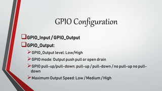
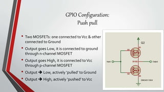
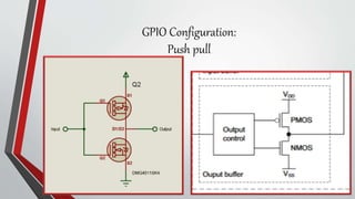
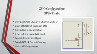
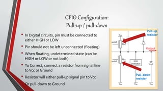
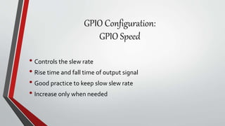
GPIO and Clock
Configuration
GPIO Interface
GPIO Output:
LED
LCD
7 –segment
GPIO Input:
Key/switch
Keypad
What are the GPIO Configuration
parameters???
GPIO Configuration
GPIO_Input / GPIO_Output
GPIO_Output:
GPIO_Output level: Low/High
GPIO mode: Output push pull or open drain
GPIO pull-up/pull-down: pull-up / pull-down / no pull-up no pull-
down
Maximum Output Speed: Low / Medium / High
GPIO Configuration
What is Push-Pull &
What is Open Drain????
GPIO Configuration:
Push pull
• Two MOSFETs: one connected toVcc & other
connected to Ground
• Output goes Low, it is connected to ground
through n-channel MOSFET
• Output goes High, it is connected toVcc
through p-channel MOSFET
• Output  Low, actively ‘pulled’ to Ground
• Output  High, actively ‘pushed’ toVcc
GPIO Configuration:
Push pull
GPIO Configuration:
OPEN Drain
• Only one MOSFET; only n-channel MOSFET
• Drain of MOSFET taken out of IC
• Only active in one direction
• It can pull the towards Ground
• Cannot drive toVcc (High)
• Switch OFF  Output Floating
• Needs a Pull-up resistor
GPIO Configuration:
Pull-up / pull-down
• In Digital circuits, pin must be connected to
either HIGH or LOW
• Pin should not be left unconnected (floating)
• When floating, undetermined state (can be
HIGH or LOW or not both)
• To Correct, connect a resistor from signal line
toVcc or Ground
• Resistor will either pull-up signal pin toVcc
• Or pull-down to Ground
Pull-up
resistor
Pull-down
resistor
Output
GPIO Configuration:
GPIO Speed
• Controls the slew rate
• Rise time and fall time of output signal
• Good practice to keep slow slew rate
• Increase only when needed
GPIO Configuration:
GPIO Input
• Input with internal pull-up; input signal pulled-up toVcc
• Input with internal pull-down ; input signal pulled-down to
Ground
• Floating Input; Signal level follows the external signal
• No external signal; Schmitt trigger toggles between logical levels
induced by external noise on pin

GPIO.pptx

  • 1.
  • 2.
    GPIO Interface GPIO Output: LED LCD 7–segment GPIO Input: Key/switch Keypad
  • 3.
    What are theGPIO Configuration parameters???
  • 4.
    GPIO Configuration GPIO_Input /GPIO_Output GPIO_Output: GPIO_Output level: Low/High GPIO mode: Output push pull or open drain GPIO pull-up/pull-down: pull-up / pull-down / no pull-up no pull- down Maximum Output Speed: Low / Medium / High
  • 5.
    GPIO Configuration What isPush-Pull & What is Open Drain????
  • 6.
    GPIO Configuration: Push pull •Two MOSFETs: one connected toVcc & other connected to Ground • Output goes Low, it is connected to ground through n-channel MOSFET • Output goes High, it is connected toVcc through p-channel MOSFET • Output  Low, actively ‘pulled’ to Ground • Output  High, actively ‘pushed’ toVcc
  • 7.
  • 8.
    GPIO Configuration: OPEN Drain •Only one MOSFET; only n-channel MOSFET • Drain of MOSFET taken out of IC • Only active in one direction • It can pull the towards Ground • Cannot drive toVcc (High) • Switch OFF  Output Floating • Needs a Pull-up resistor
  • 9.
    GPIO Configuration: Pull-up /pull-down • In Digital circuits, pin must be connected to either HIGH or LOW • Pin should not be left unconnected (floating) • When floating, undetermined state (can be HIGH or LOW or not both) • To Correct, connect a resistor from signal line toVcc or Ground • Resistor will either pull-up signal pin toVcc • Or pull-down to Ground Pull-up resistor Pull-down resistor Output
  • 10.
    GPIO Configuration: GPIO Speed •Controls the slew rate • Rise time and fall time of output signal • Good practice to keep slow slew rate • Increase only when needed
  • 11.
    GPIO Configuration: GPIO Input •Input with internal pull-up; input signal pulled-up toVcc • Input with internal pull-down ; input signal pulled-down to Ground • Floating Input; Signal level follows the external signal • No external signal; Schmitt trigger toggles between logical levels induced by external noise on pin