Downloaded 3,169 times
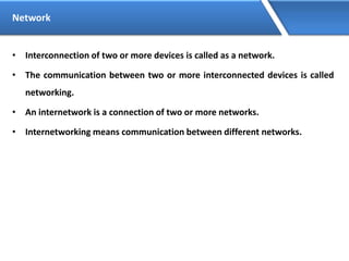
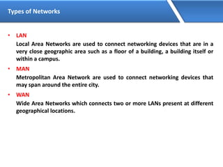
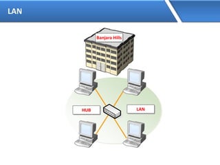
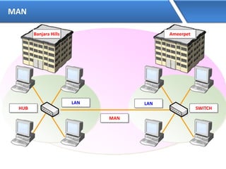
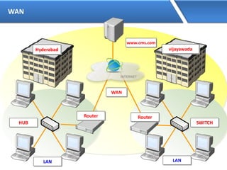
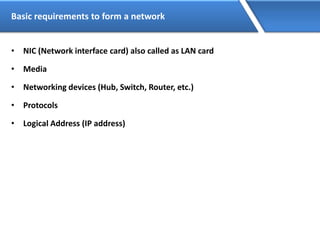
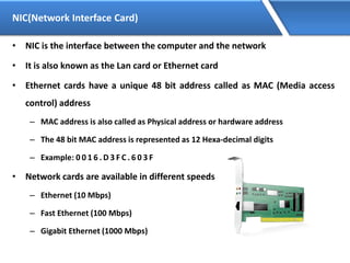
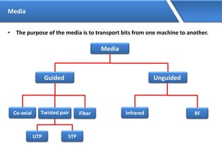


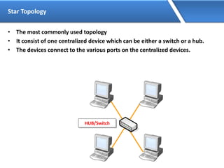

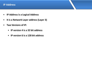

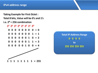
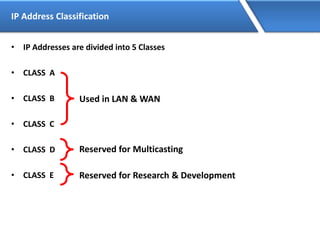


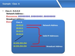
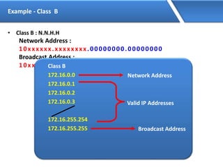
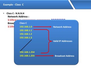
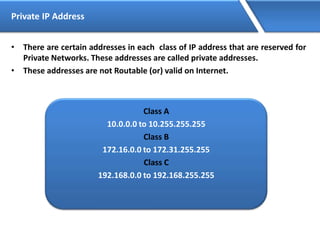


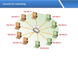


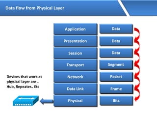
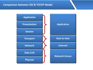

Networking allows devices to interconnect and communicate. The basic components required for a network are networking devices like switches and routers, network interfaces cards for each device, cabling or wireless media to connect the devices, and network protocols for communication. Common network types include LAN, MAN and WAN. LAN connects devices within a building, MAN within a city, and WAN connects LANs over long distances. IP addressing using IPv4 addresses in dot decimal notation like 192.168.1.1 is required for devices to communicate on a network.