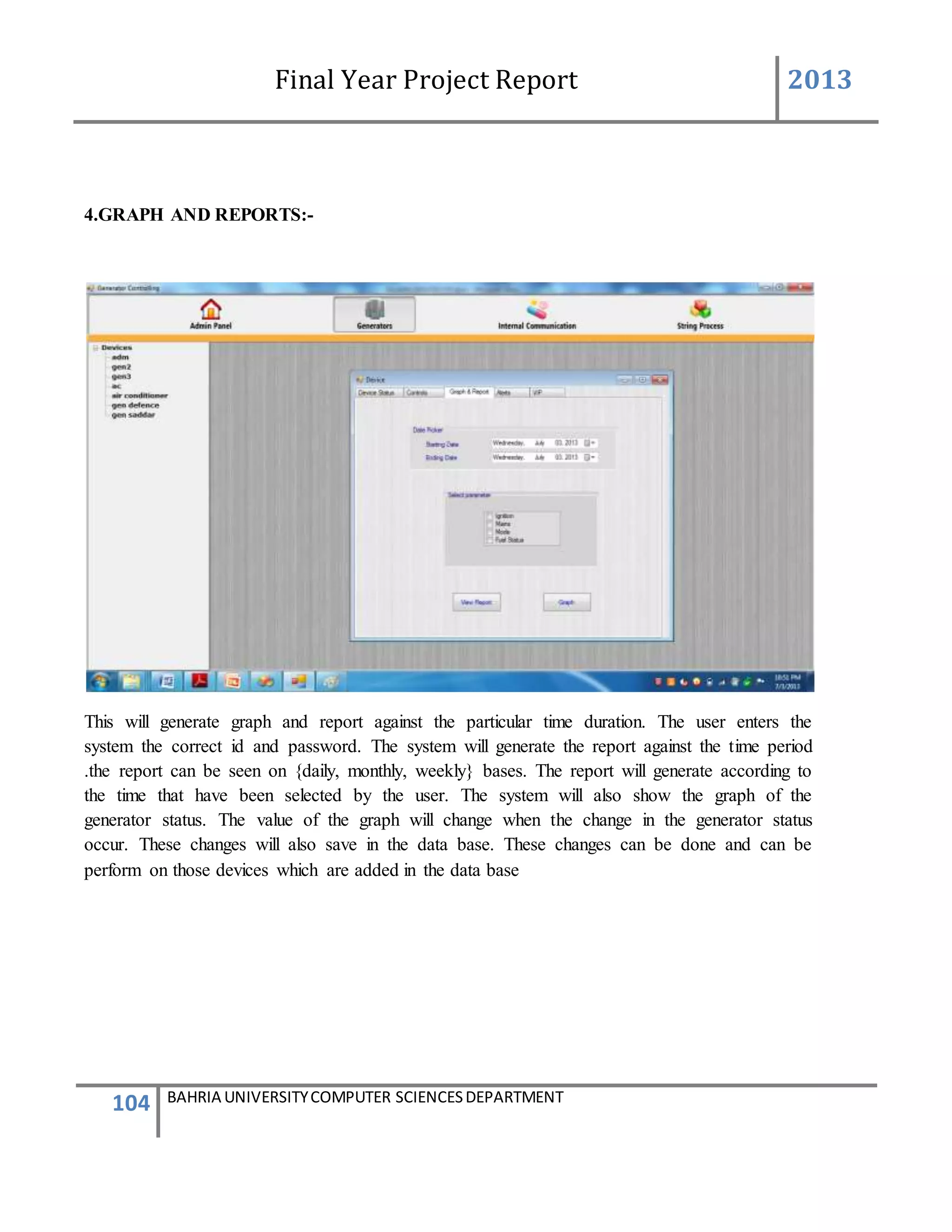
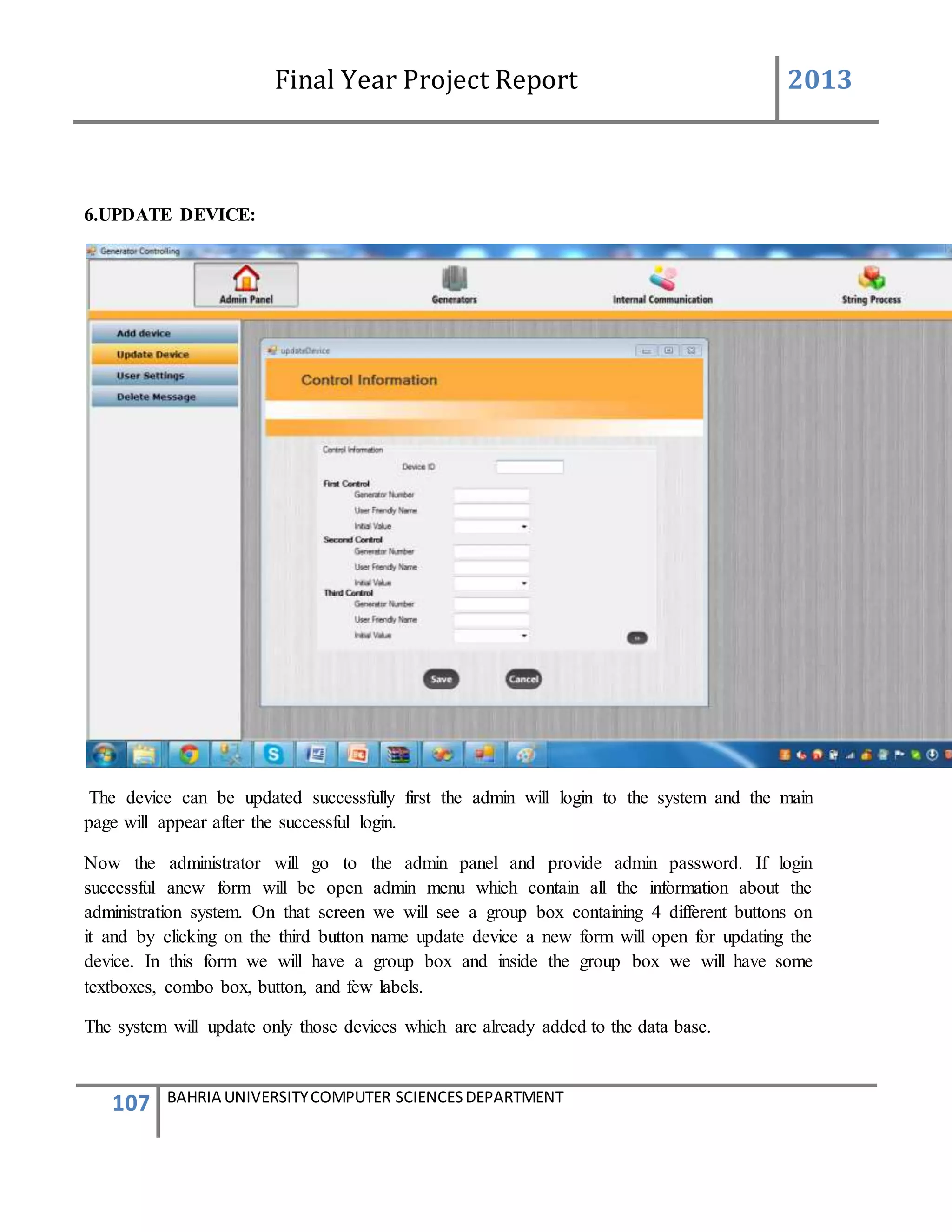
This document is a final year project report submitted by Salman Ahmed and Faisal Khan to Bahria University's Computer Science department in 2013. The report describes the development of a Generator Monitoring System that uses GSM technology to automatically monitor generators, update their status, control their functions, generate reports, and send alerts. The system was created to reduce the need for manual monitoring of generators located at different sites. The project used a waterfall development methodology, including planning, requirements analysis, design, implementation, testing, and conclusion phases.
![Final Year Project Report 2013
24 BAHRIA UNIVERSITYCOMPUTER SCIENCESDEPARTMENT
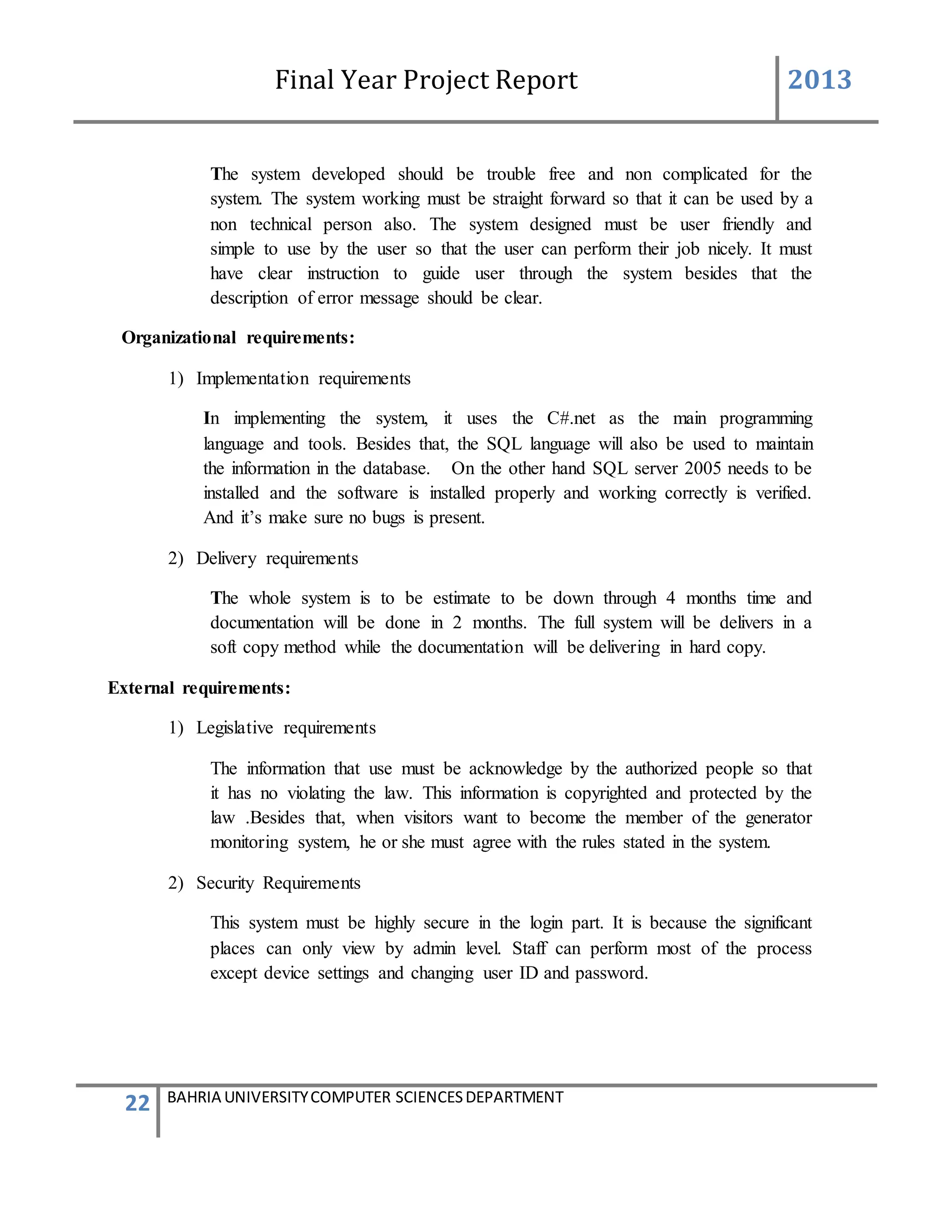
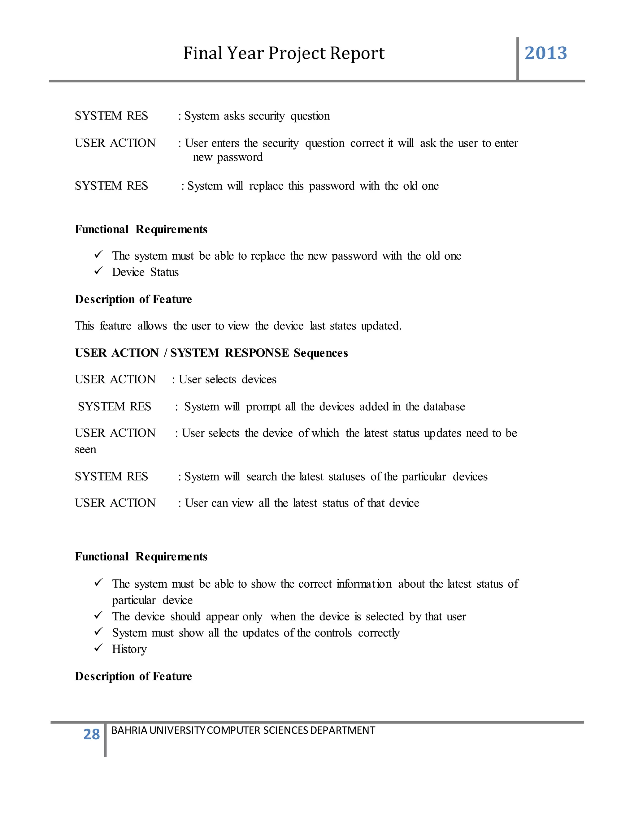
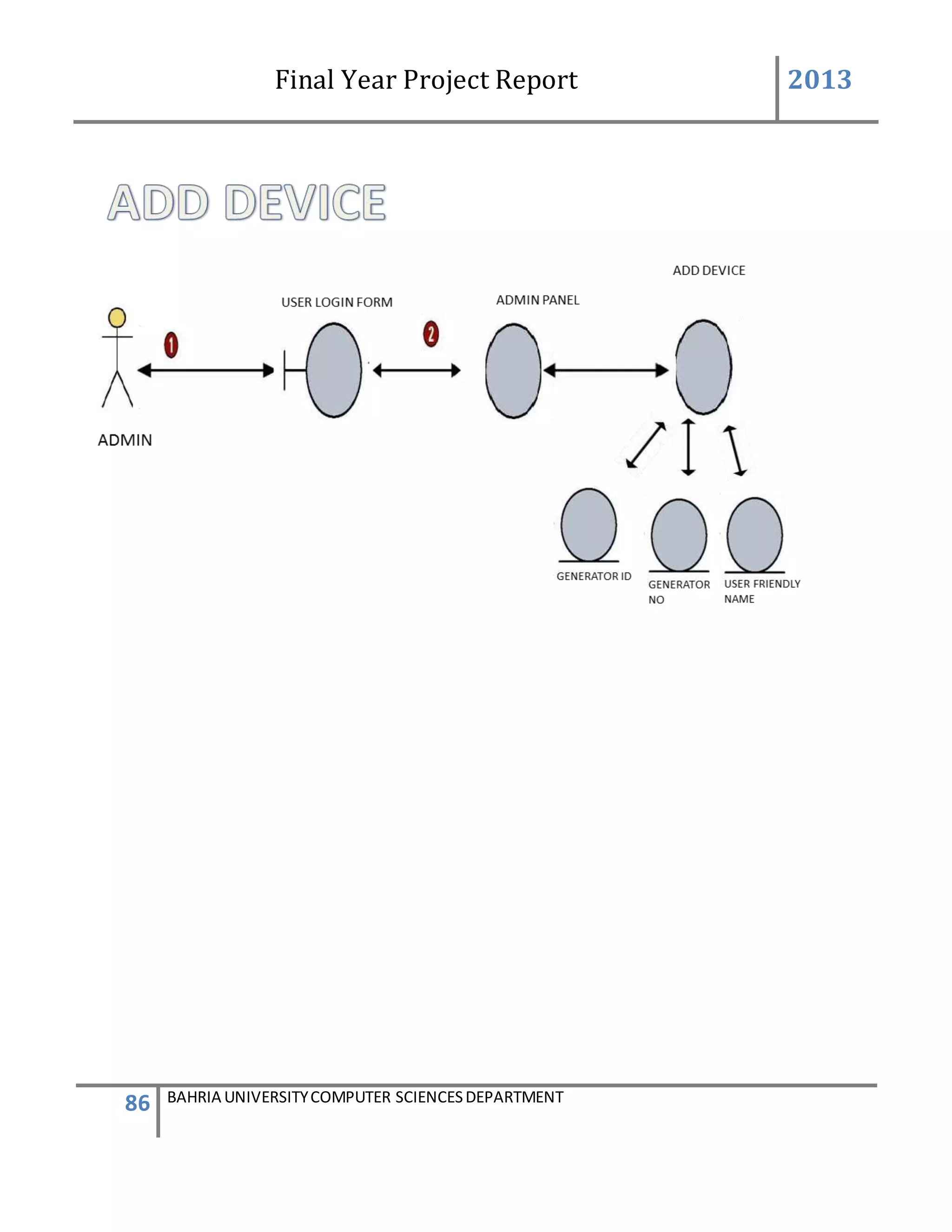
Description of Feature
This feature can be performing by only Admin to add new device.
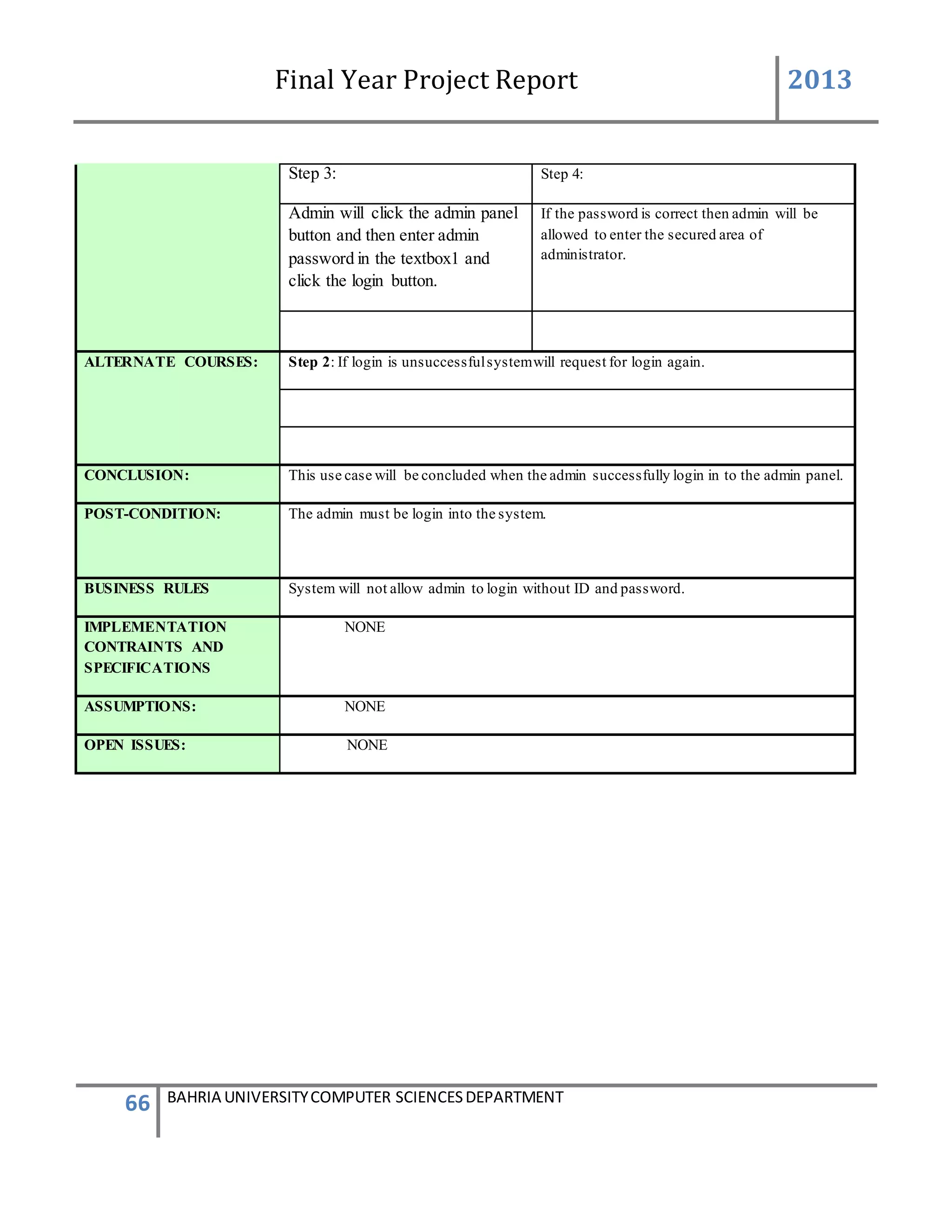
USER ACTION / SYSTEM RESPONSE Sequences
USER ACTION : Admin press Add new Device
SYSTEM RES : System prompts Add Device form
USER ACTION : In the Add Device form Device ID is system generated .Admin
enters the user friendly name of the device, generator ID of the
device, add user friendly controls name and their defined VIP
numbers of person to which the message will be send and defined
messages which will be given to that VIP numbers.
SYSTEM RES : System will validate the information such as the number is in
correct format. If all the information was entered correctly.
system will add the device into [Device] table and
add[Device Info] table. After ,enter into database, system will
prompts a message box stated that the device was enter
successfully.
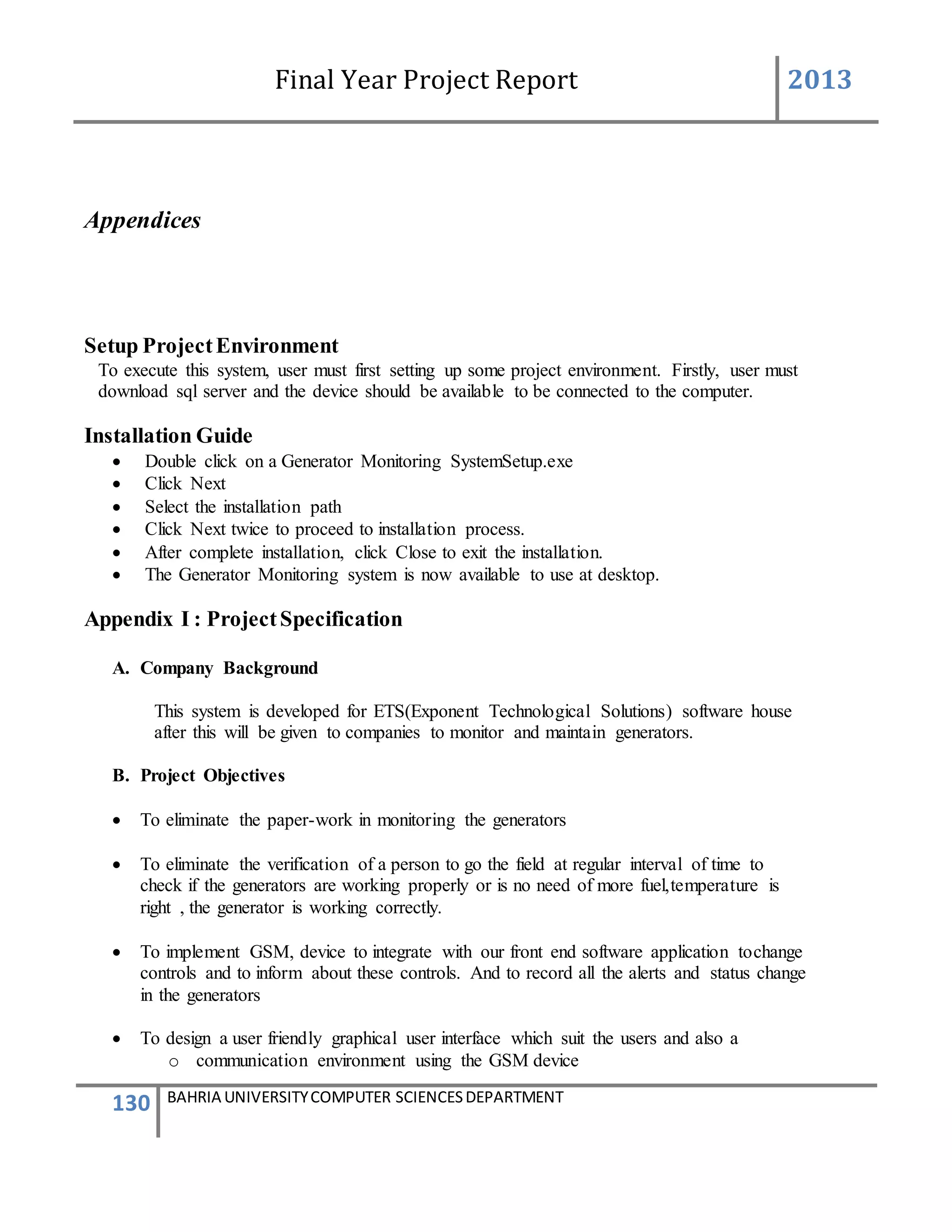
Functional Requirements
System must be able to auto generate the Device ID
System must not generate the same Device ID
The system must be able to verify the information
The repeated generator ID should not be allowed into the database.
Device Maintenance
Description of Feature
This feature can be performing by only admin to edit information of the device or deactivate
a device.
USER ACTION / SYSTEM RESPONSE Sequences](https://image.slidesharecdn.com/94503301-4dbb-4264-ac13-83c6c6b1f363-161222192404/75/Generator-Monitoring-System-Document-24-2048.jpg)
![Final Year Project Report 2013
25 BAHRIA UNIVERSITYCOMPUTER SCIENCESDEPARTMENT
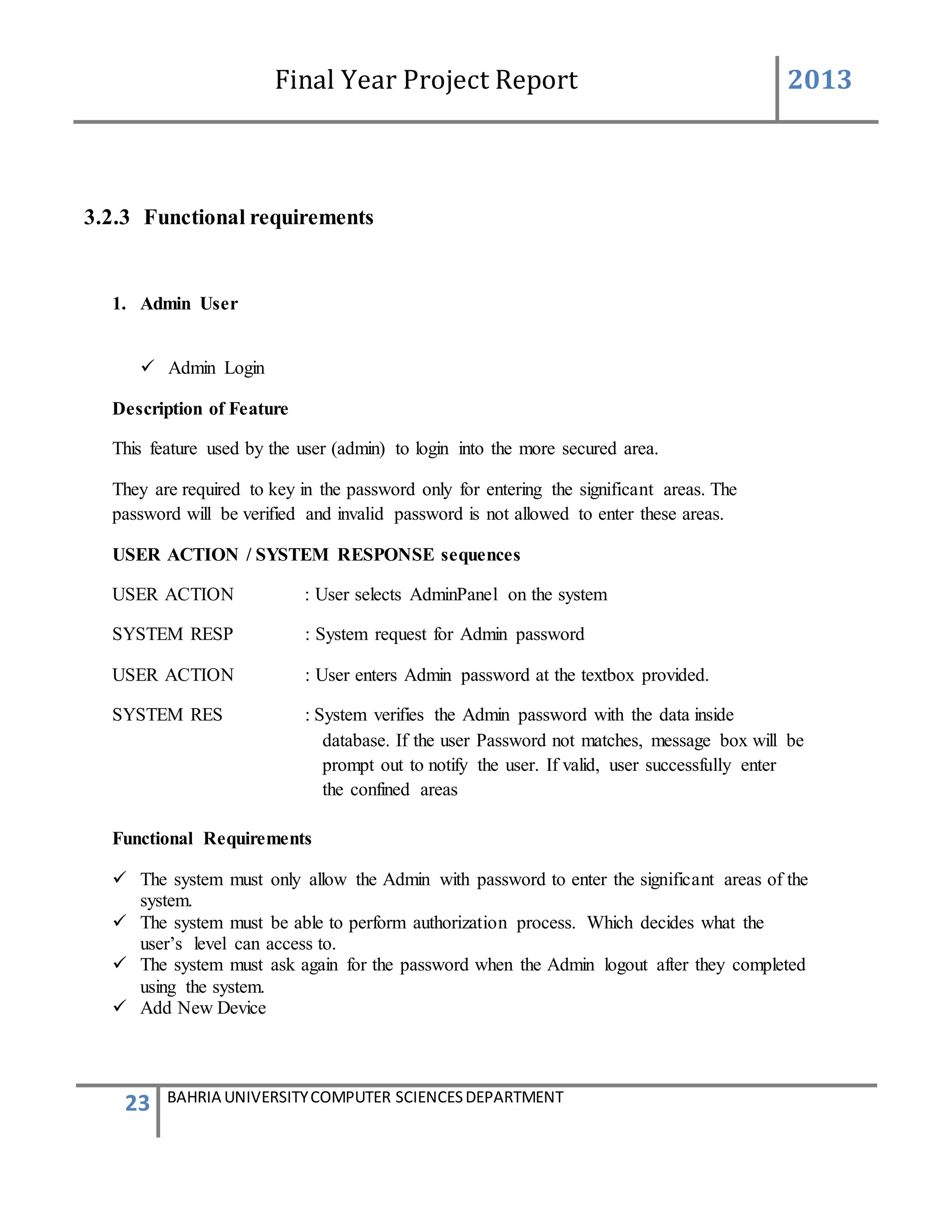
USER ACTION : User press Edit Device on the Add device form
SYSTEM RES : System prompts Edit Device form
USER ACTION : In the Edit Device form User selects the device to be edited.
SYSTEM RES : System views the selected device to be edited by the user
USER ACTION : User can edit the User friendly name of the device, generator ID of
the device, user friendly controls name and their defined VIP
numbers of person to which the message will be send and defined
messages which will be given to that VIP numbers.
SYSTEM RES : System will validate the information such as the number is in correct
format . If all the information was entered correctly. System will
edit the device into [Device] table and add[Device Info] table. After
enter into database, system will prompts a message box stated that
the device edited information replaced successfully.
Functional Requirements
The system must be able to verify the information
System must enter the correct generator ID into the device specification information
The repeated generator ID should not be allowed into the database
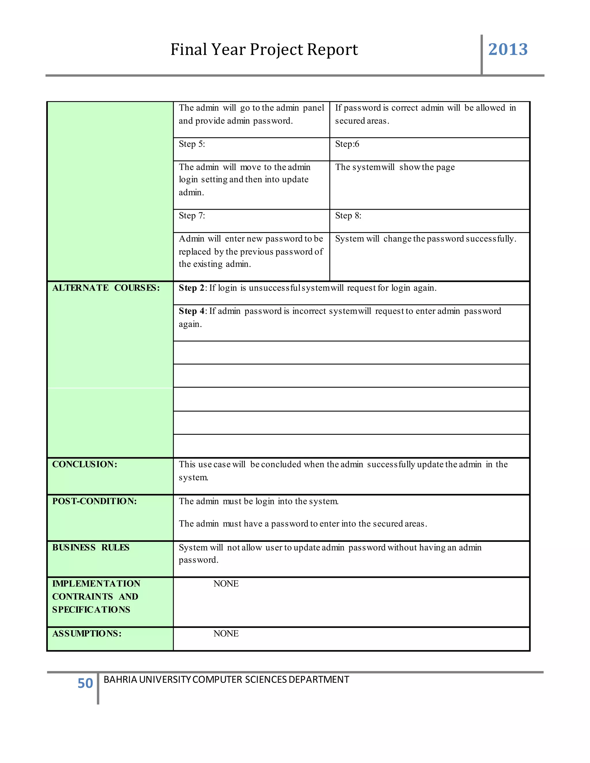
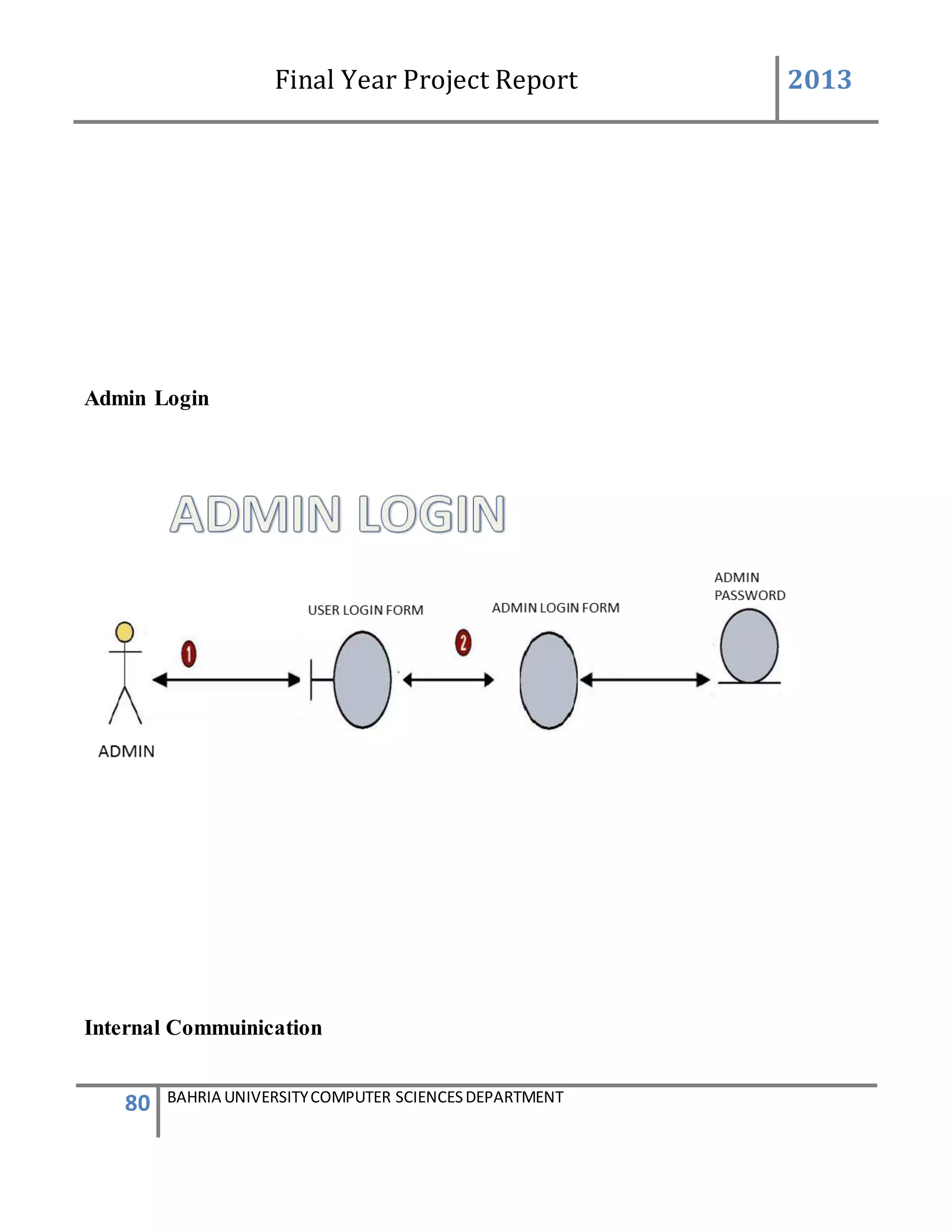
Admin Password Setting
Description of Feature
This feature can be performing by user(Admin) to change password .
USER ACTION / SYSTEM RESPONSE Sequences
USER ACTION : User press settings in the Admin Panel
SYSTEM RES : System prompts password setting
USER ACTION : In the Password Setting user presses change Admin password
SYSTEM RES : System will ask for new password to be enter into the textbox
USER ACTION : User will enter new password.](https://image.slidesharecdn.com/94503301-4dbb-4264-ac13-83c6c6b1f363-161222192404/75/Generator-Monitoring-System-Document-25-2048.jpg)


![Final Year Project Report 2013
101 BAHRIA UNIVERSITYCOMPUTER SCIENCESDEPARTMENT
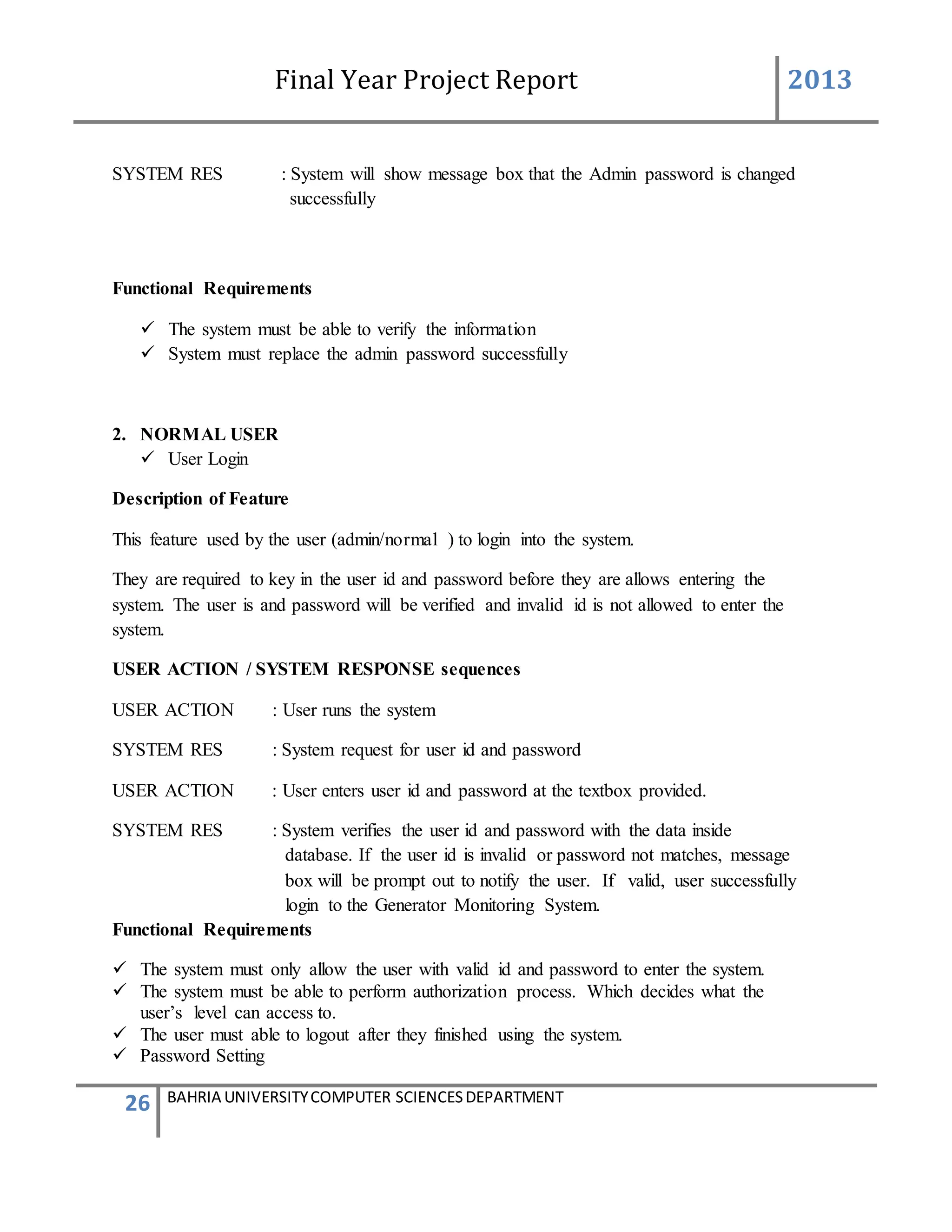
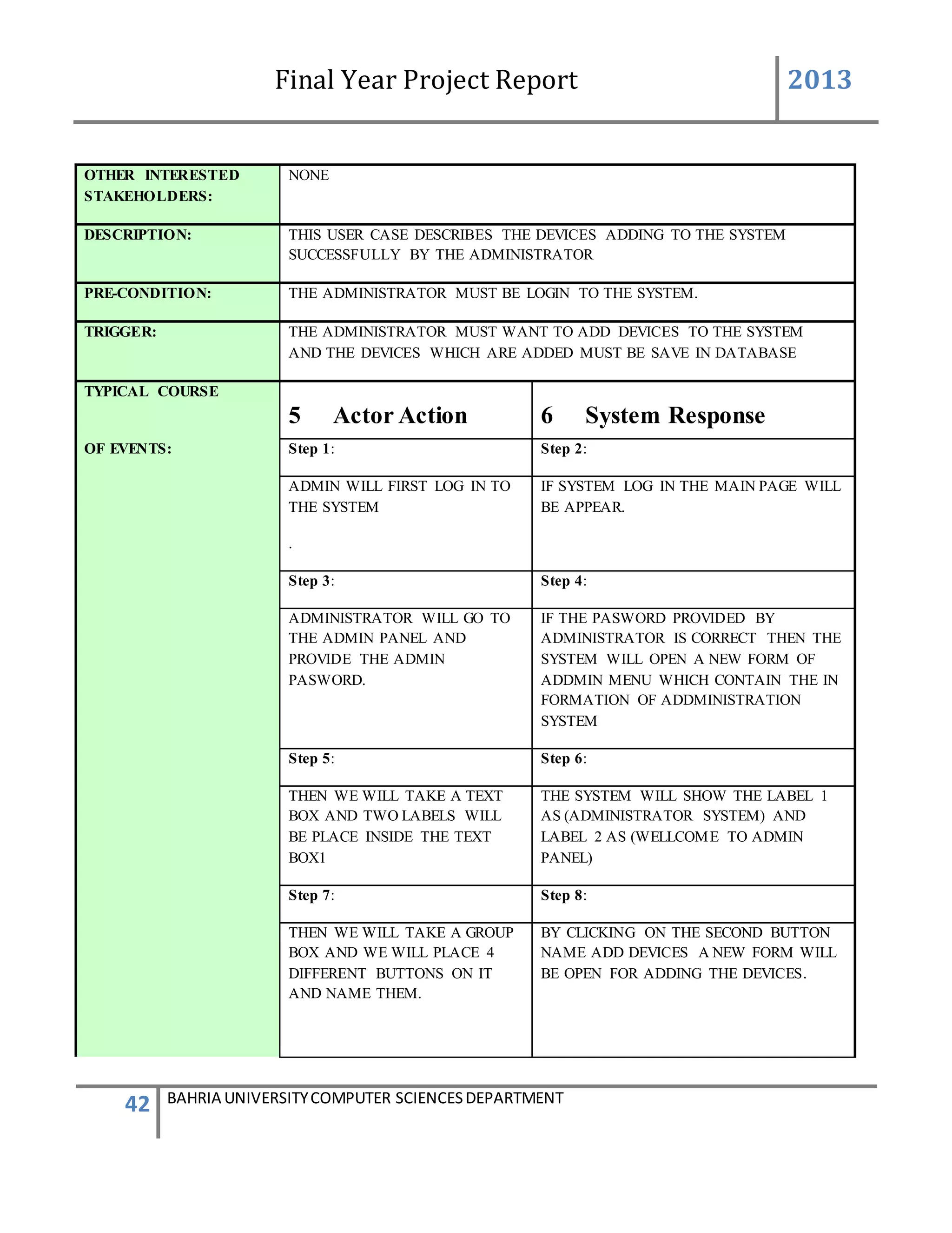
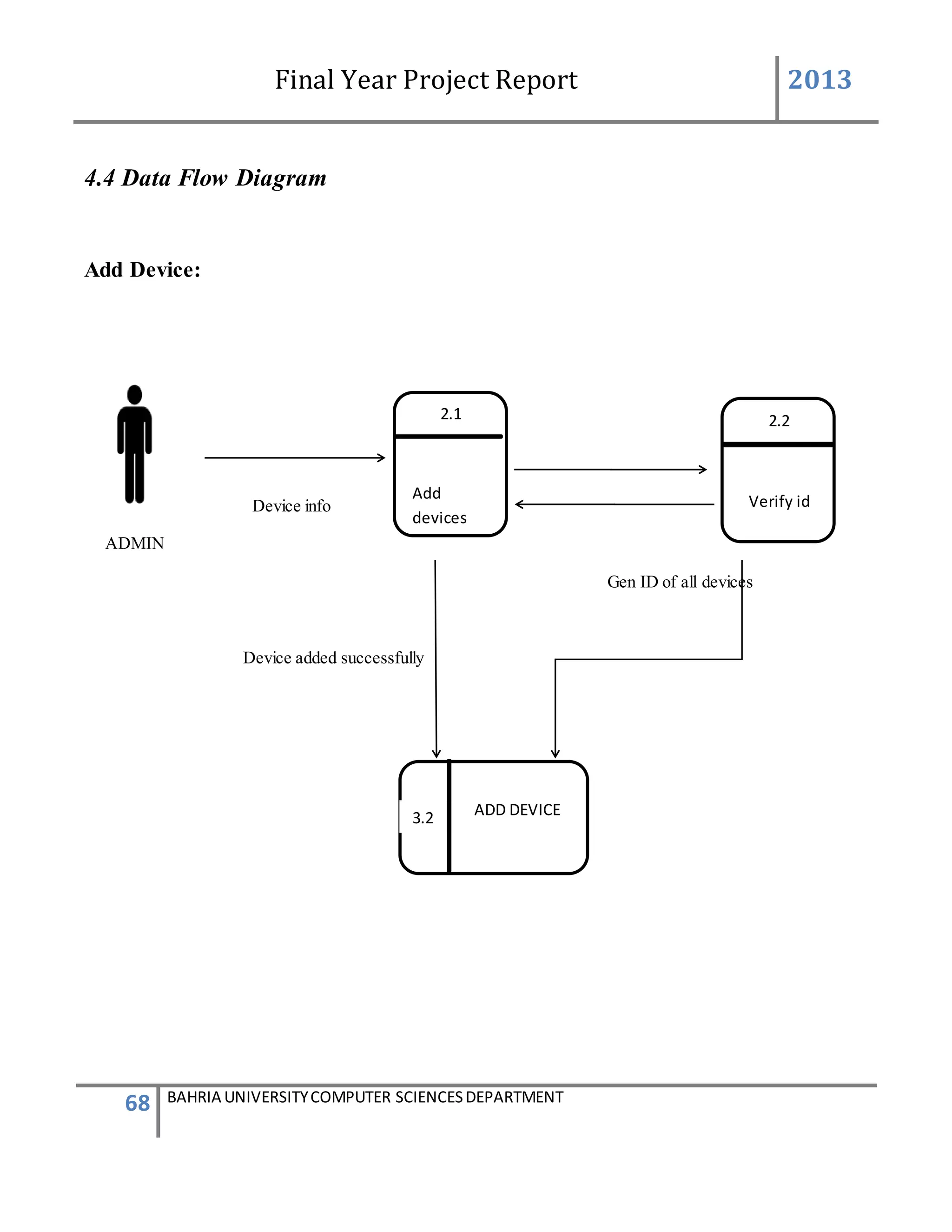
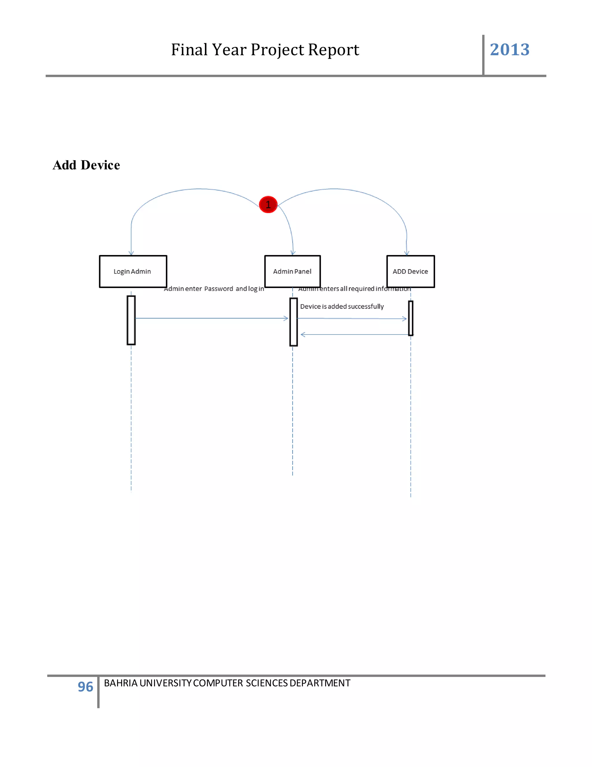
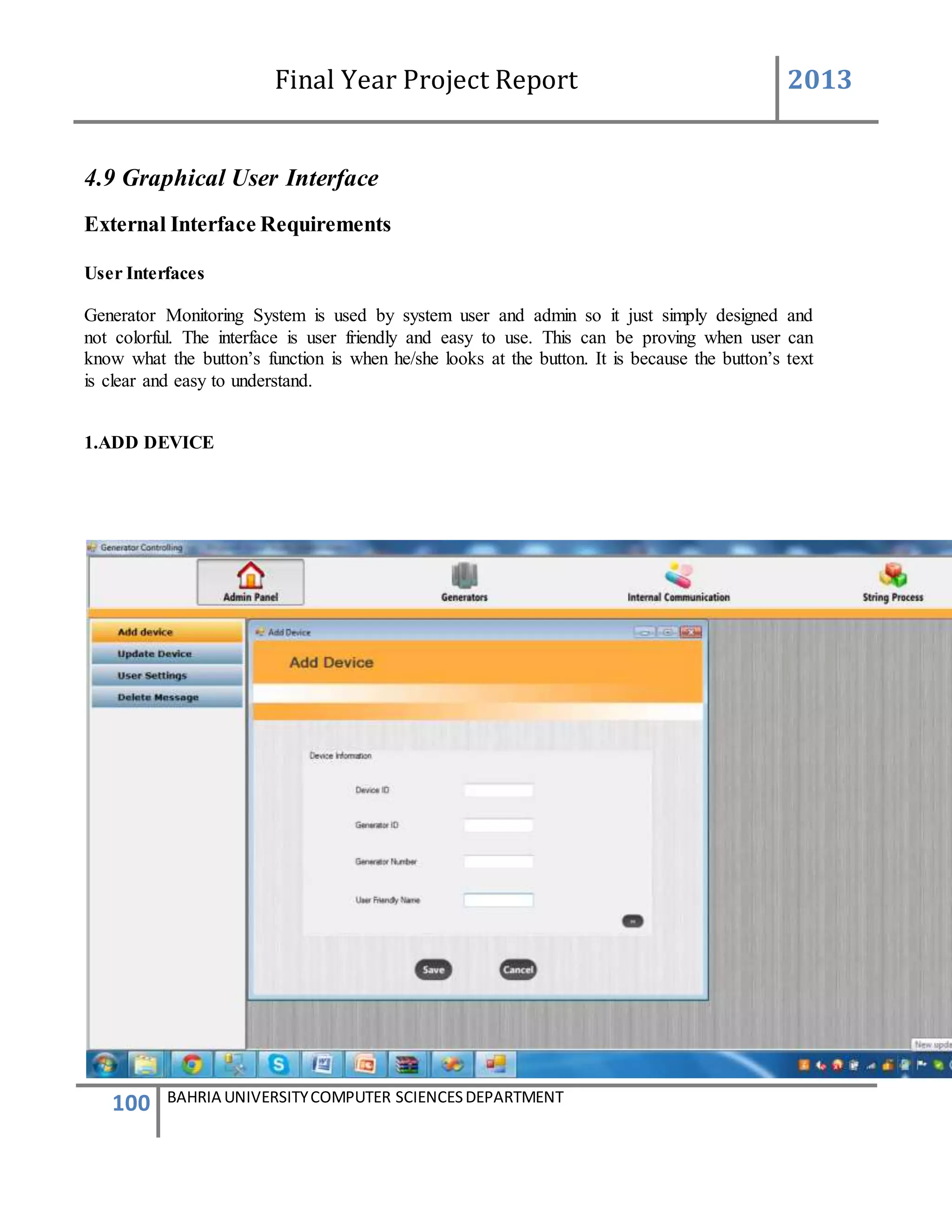
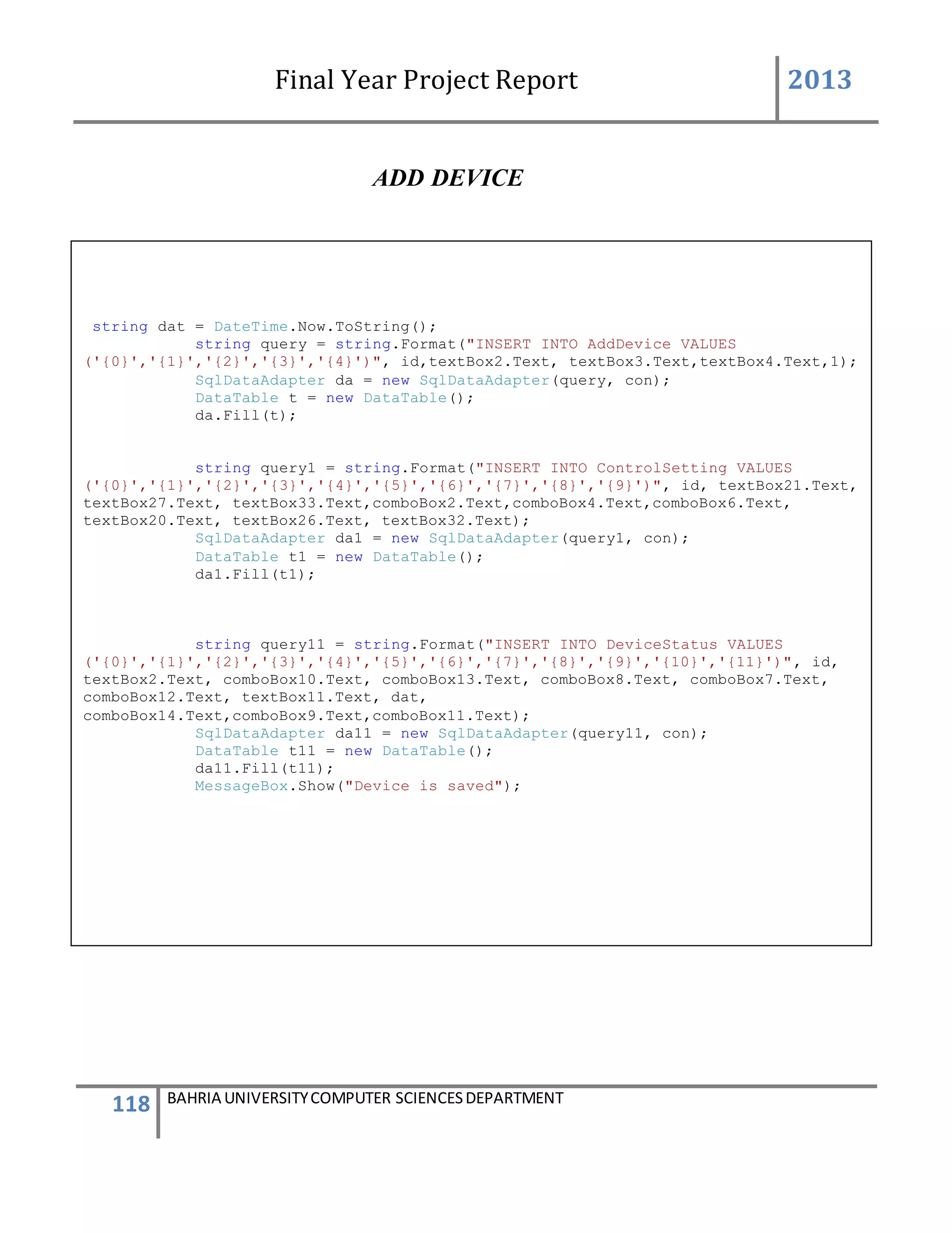
This form describes that how the device will add to system.
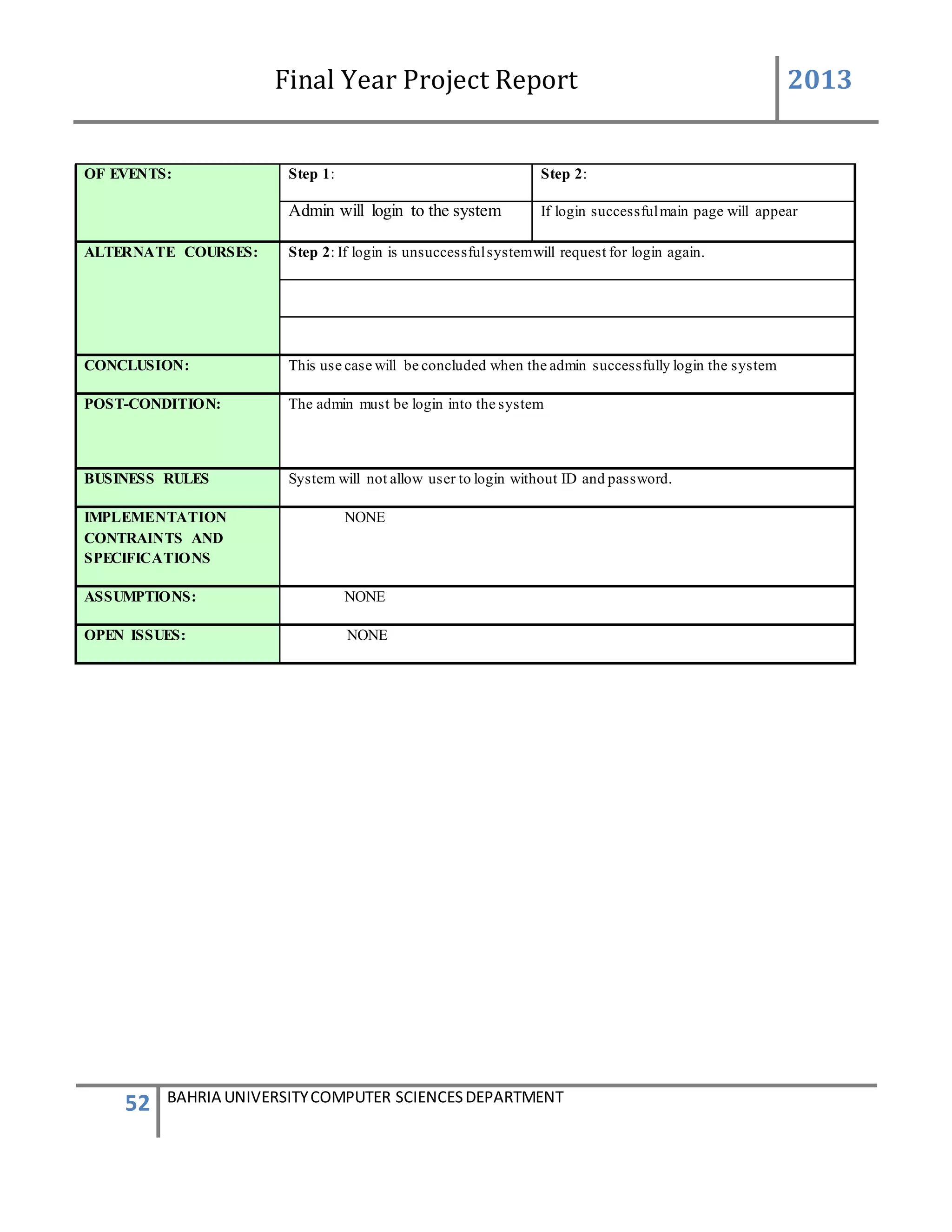
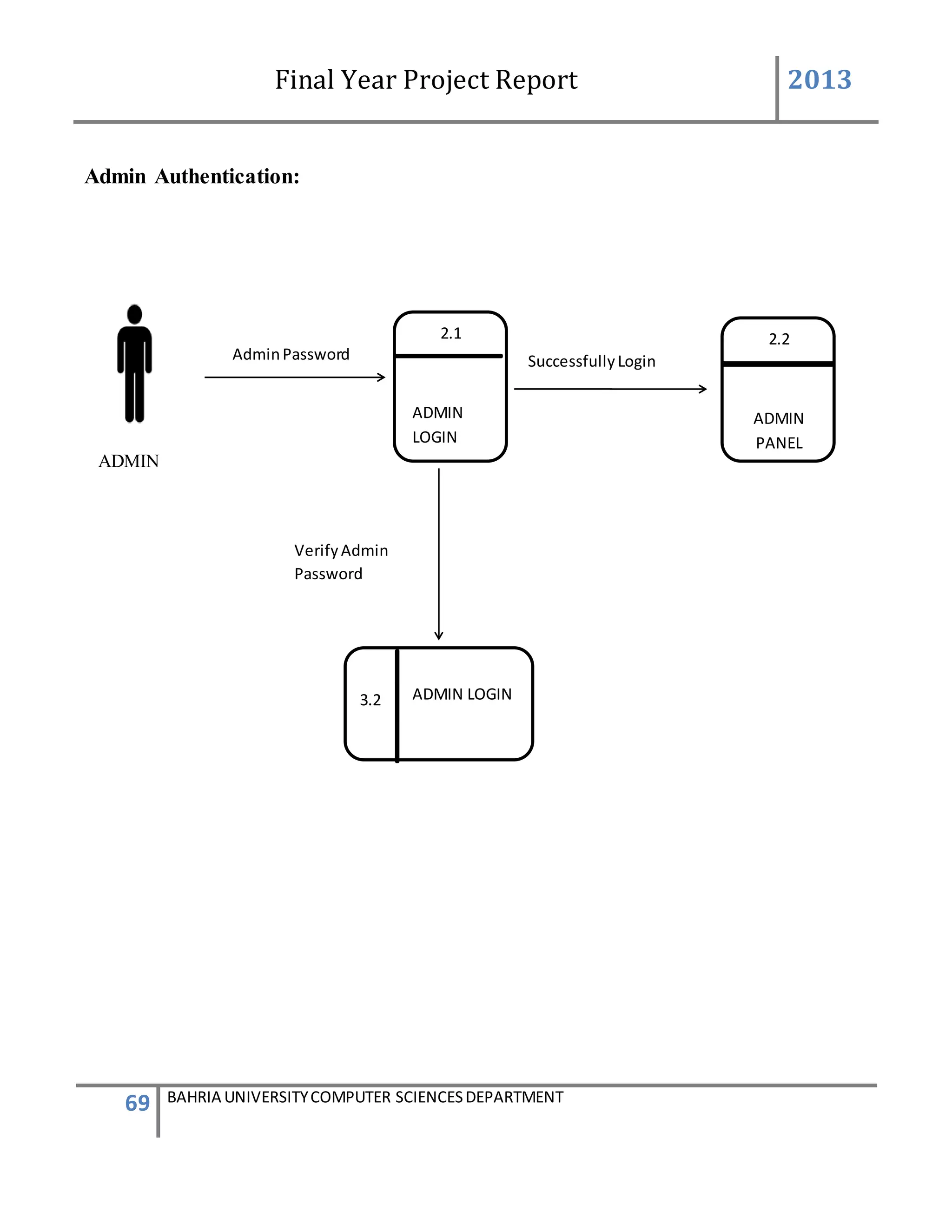
The admin will first login to the system. If the id and password provide by the system is correct
then the main screen appears. The administrator will go to the admin panel and will again
provide a admin password. After entering in the admin panel it contain the information of
administration system. There will be a group box having 4 different buttons. By clicking on the
second button name add device a new form will be appear for adding the device.
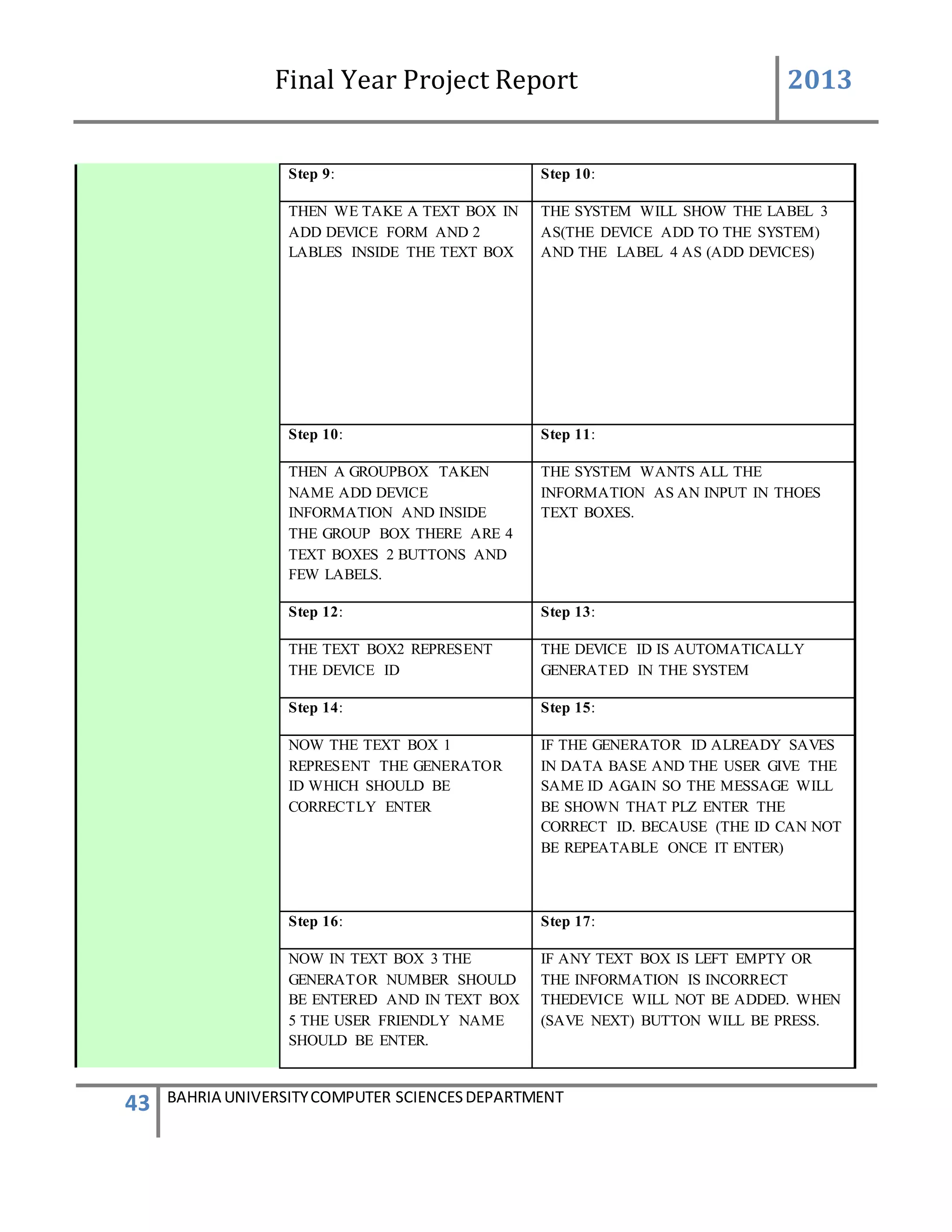
In add device form we take text box and labels the label3 and label4 name (add devices to the
system) and (add device). Then we again take a group box and inside the group box we take 4
text boxes 2 button and few labels. The user must enter all the information input in those text
boxes. The text box2 represent the device id and the device id is automatically generated by the
system with the help of data base. The text box 1 represents the generator id which should be
correctly entered. If the generator id already exist in the data base the user enter the same id
again so the message will be appear that plz enter the correct id. {The id cannot be repeated once
it enter} .now in text box 3 the generator number should be enter and in the text box5 the user
friendly name will be enter.
If any box is left empty or the information is in correct the device will not be added when the
button will (save/next)
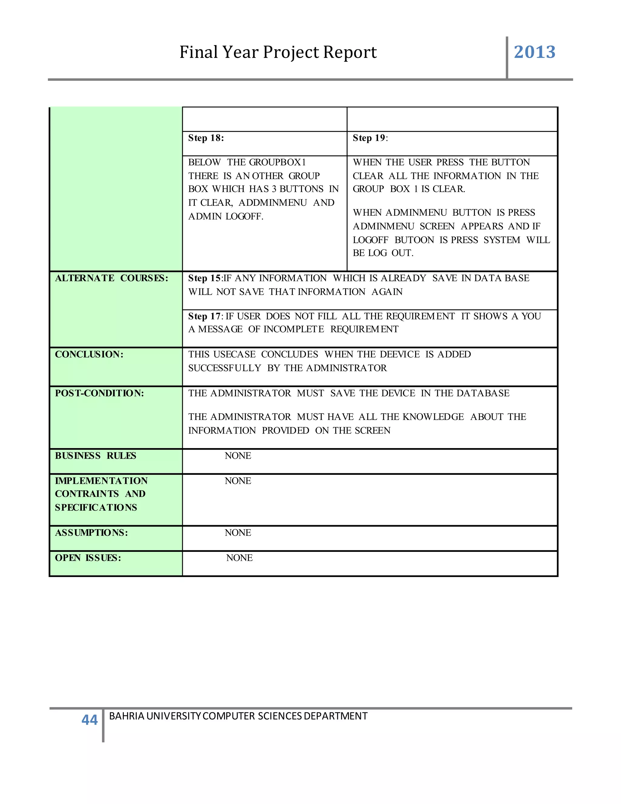
Below the group box 1 there is another group box which has 3 button in it [clear addmin menu,
admin logoff]
When the user press the button clear all the information in the group box1 is clear when admin
menu button is press admin menu screen will be appear and if log off button is press system will
be log out.
By adding the device the device must be save in the data base or added in the data base all the
knowledge on the screen must be known to the user](https://image.slidesharecdn.com/94503301-4dbb-4264-ac13-83c6c6b1f363-161222192404/75/Generator-Monitoring-System-Document-101-2048.jpg)
![Final Year Project Report 2013
105 BAHRIA UNIVERSITYCOMPUTER SCIENCESDEPARTMENT
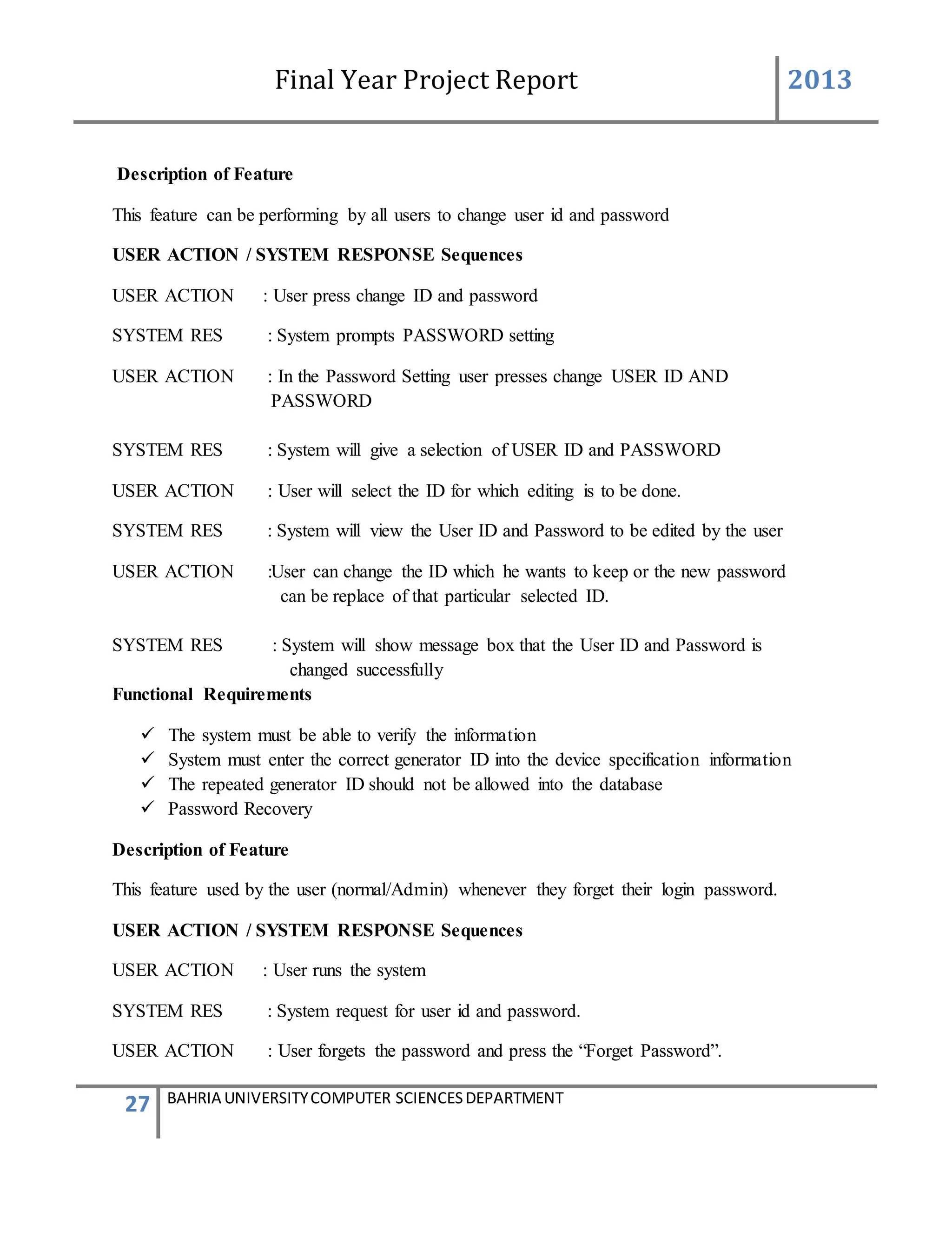
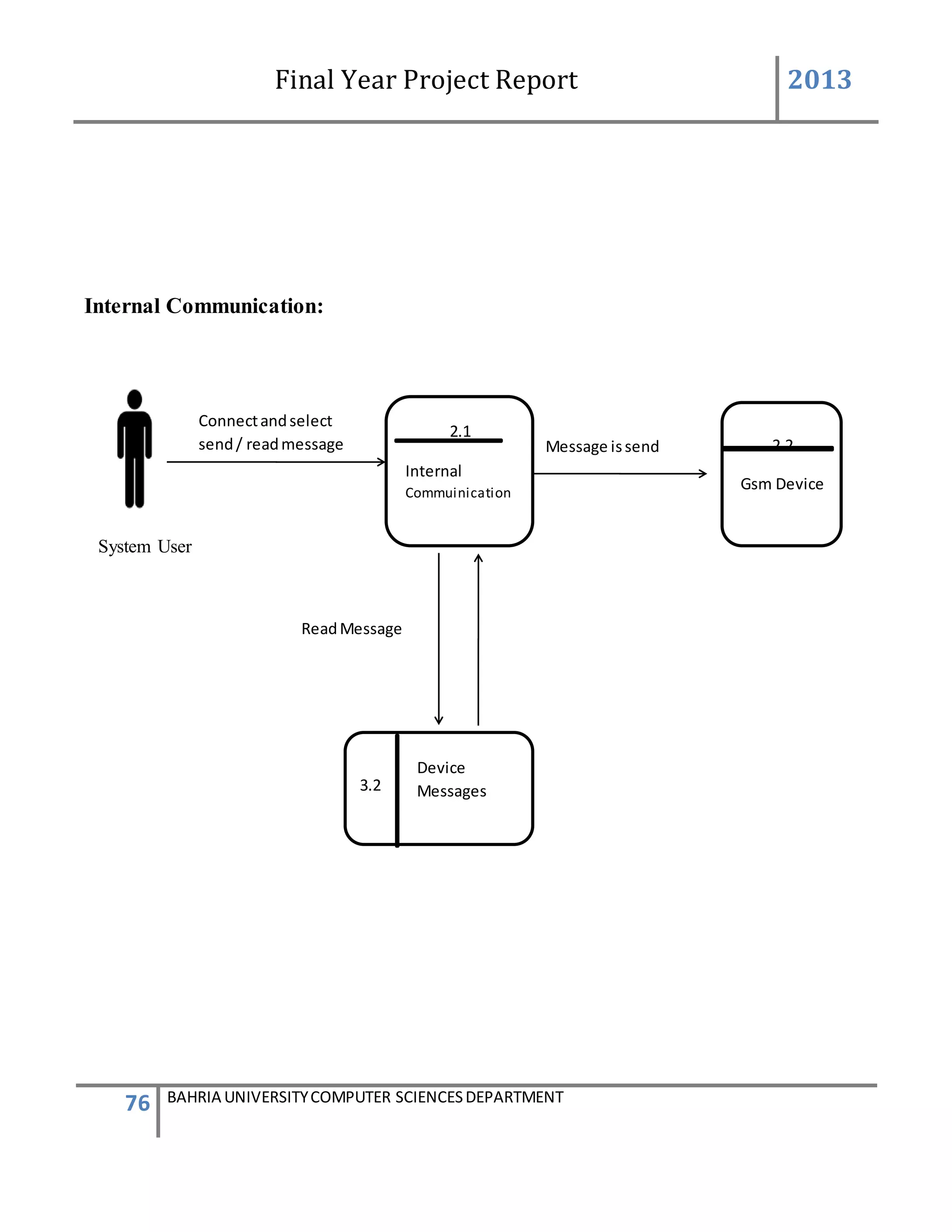
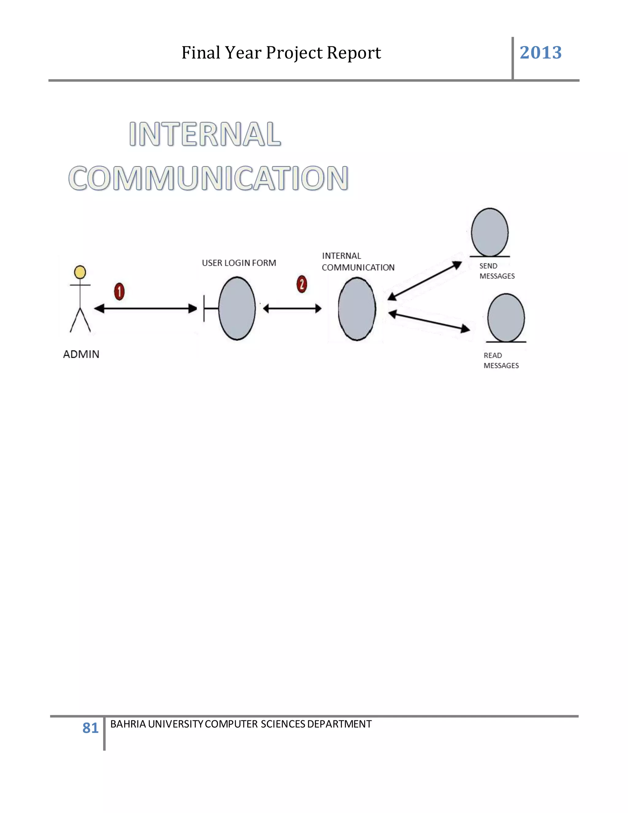
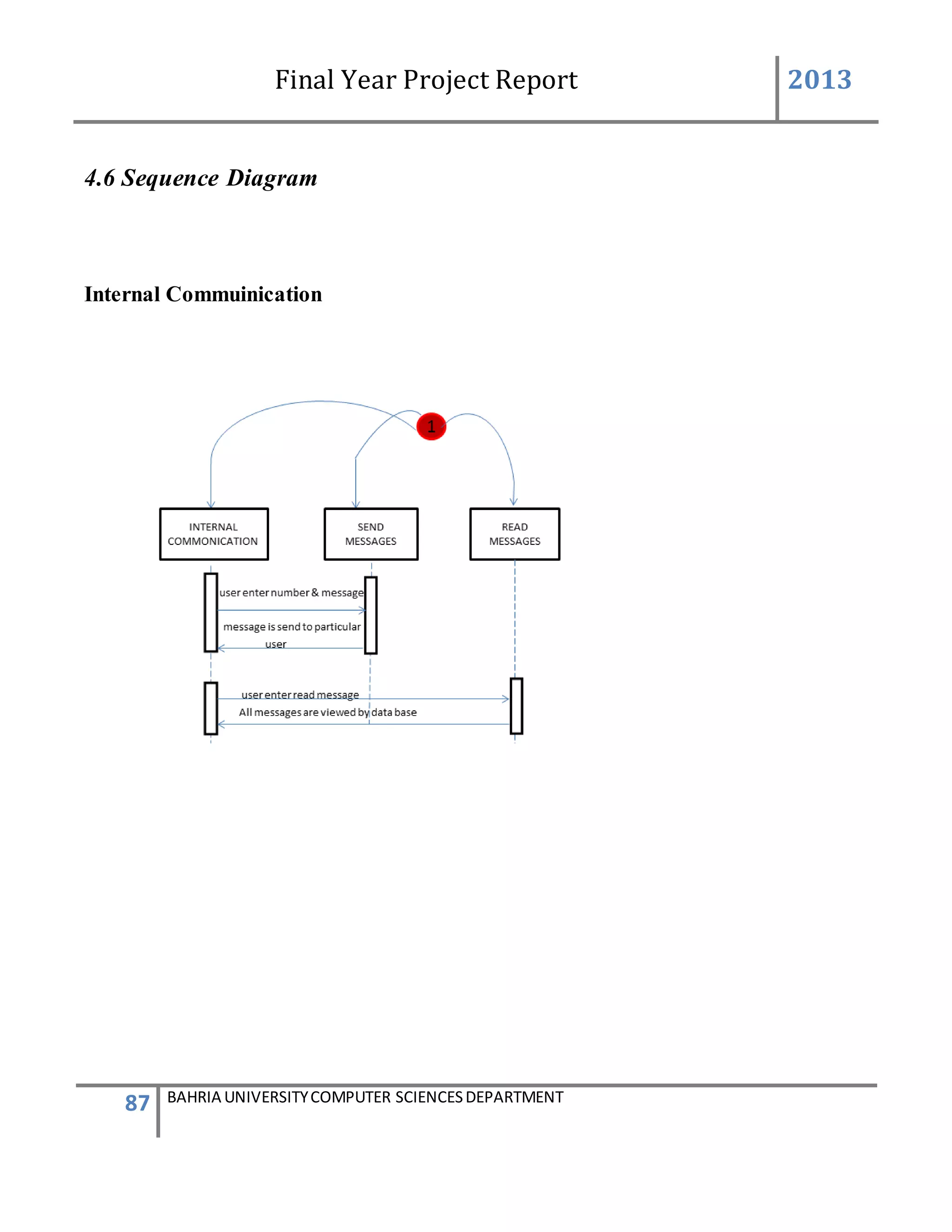
5.INTERNAL COMMUNICATION:
The internal communication describes the connection of the GSM device to the system
successfully and helping in sending and receiving messages.
The admin will log on to the system. After login successfully the main page of the system will be
appear.
On the main page there is the button number6 name “internal communication” and by clicking
on the button anew screen of internal communication occur this screen consist of the tab control
taken, inside the tab control there are four (4) tabs taken [name, port setting, send SMS, read
SMS and delete SMS] and by clicking on the individual tab individual screen appear and having
different properties. The first tab control name port setting make connection. The port set contain
different properties. The port name is detected by the system automatically and the baud rate is
always (9600) while the other properties remain constant.
There is a button name “connect” also lies in the group box by pressing the button the
connection will be establish between the GSM device and the software system.](https://image.slidesharecdn.com/94503301-4dbb-4264-ac13-83c6c6b1f363-161222192404/75/Generator-Monitoring-System-Document-105-2048.jpg)
![Final Year Project Report 2013
117 BAHRIA UNIVERSITYCOMPUTER SCIENCESDEPARTMENT
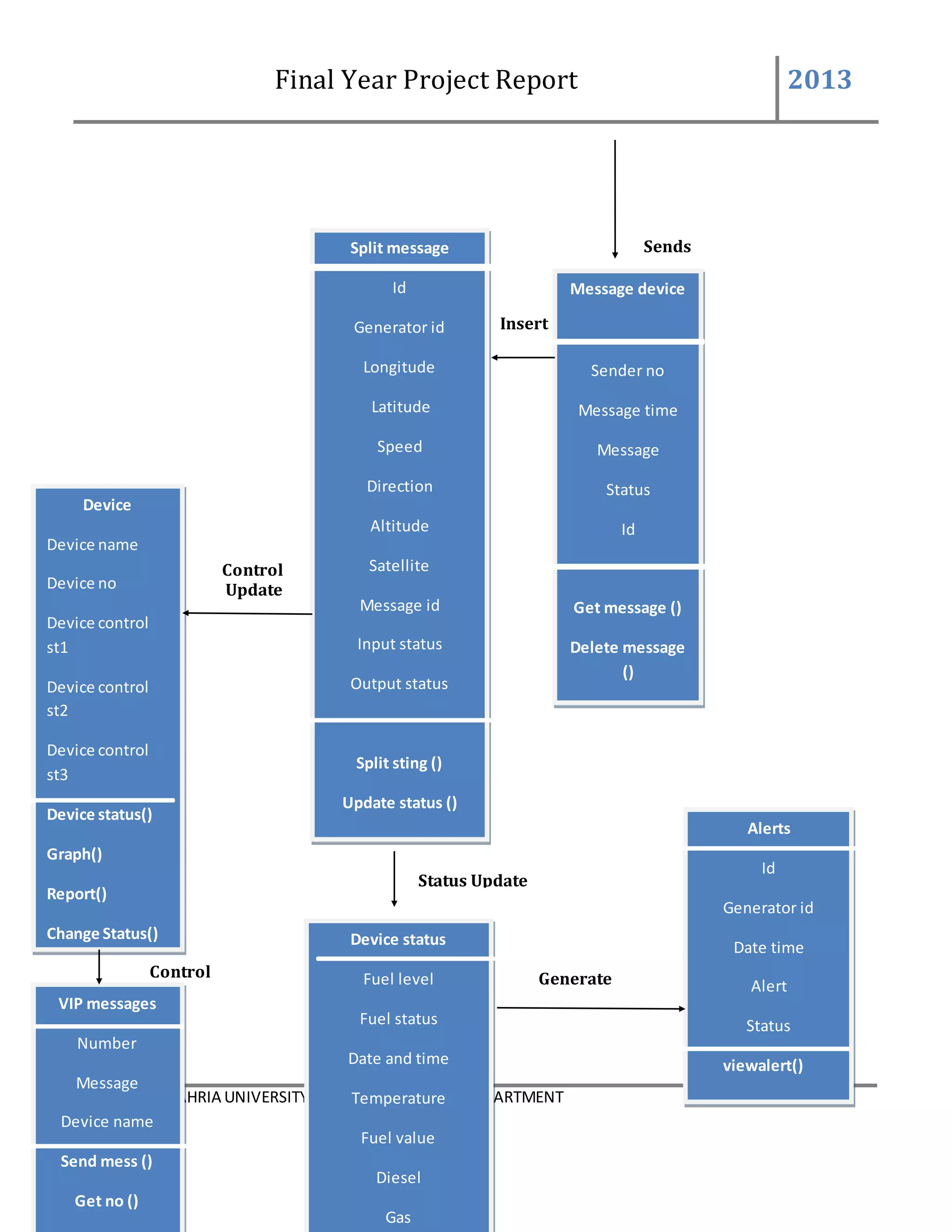
SPLIT MESSAGE
public void message()
{
int comma = 0;
label7.Visible = false;
foreach (char c in messagetext)
{
if (c == ',')
{
comma = comma + 1;
}
}
if (comma >=14)
{
string[] wordArray = messagetext.Split(',');
textBox3.Text = wordArray[0];
double a = Convert.ToDouble(textBox3.Text);
textBox4.Text = wordArray[2];
decimal longitude = Convert.ToDecimal(textBox4.Text);
textBox5.Text = wordArray[3];
decimal latitude = Convert.ToDecimal(textBox5.Text);
textBox6.Text = wordArray[4];
int speed = Convert.ToInt32(textBox6.Text);
textBox7.Text = wordArray[5];
int direction = Convert.ToInt32(textBox7.Text);
textBox8.Text = wordArray[6];
int altitude = Convert.ToInt32(textBox8.Text);
textBox9.Text = wordArray[7];
int satellites = Convert.ToInt32(textBox9.Text);
textBox10.Text = wordArray[8];
int messageid = Convert.ToInt32(textBox10.Text);
textBox11.Text = wordArray[9];
inputstatus = Convert.ToInt32(textBox11.Text);
textBox12.Text = wordArray[10];
outputstatus = Convert.ToInt32(textBox12.Text);
textBox13.Text = wordArray[11];
analoginput1 = Convert.ToDecimal(textBox13.Text);
textBox14.Text = wordArray[12];
analoginput2 = Convert.ToDecimal(textBox14.Text);
textBox15.Text = wordArray[13];
// int rtc = Convert.ToInt32(textBox15.Text);
textBox16.Text = wordArray[14];
double mileage = Convert.ToDouble(textBox16.Text);
int first = 1;
string username;
DataTable dt1 = new DataTable();
DataTable allDt = new DataTable();
string allQuery = string.Format("select * from AddDevice");
SqlDataAdapter allDa = new SqlDataAdapter(allQuery, con);
allDa.Fill(allDt);
for (int k = 0; k < allDt.Rows.Count; k++)
{](https://image.slidesharecdn.com/94503301-4dbb-4264-ac13-83c6c6b1f363-161222192404/75/Generator-Monitoring-System-Document-117-2048.jpg)
![Final Year Project Report 2013
128 BAHRIA UNIVERSITYCOMPUTER SCIENCESDEPARTMENT
References
Give all references.
[1] “COCOMO calculation” Available at:
http://img.docstoccdn.com/thumb/orig/116237365.png
[2] Ali A, F.D Allen. “Guidelines for Final Year Project-2010”. Available at:
www.projects.edu.pk. Accessed June 2012.
[3] “AT CommandsFor WirelessGSM/GPRSModemswithIPConnectivity”. Available at:
http://www.embeddedarm.com/documentation/third-party/tsmodem2_developerguide-
gsm-gprs-ip-commands-s000333b.pdf
[4] “GSM CONNECTIVITYATCOMMANDS”. Available at:
http://www.smsiseasy.com/technicalinfo.html
[5] “Check for Serial port modem connection status”. Available at:
http://stackoverflow.com/questions/15803318/check-for-serial-port-gsm-modem-
connection-status
[6] “Monitoring Software Review”. Available at:
http://monitoring-software-review.toptenreviews.com/
[7] “Learn how to write a review of literature”. Available at:
http://writing.wisc.edu/Handbook/ReviewofLiterature.html
[8] “SMS REMOTE CONTROLLER ”. Available at:
www.lamarca.org/flight/GSMproject.pdf
[9] “real time vehicle tracking system using gsm and gps technology- an anti-theft
tracking system.PDF”. Available at:
www.techrepublic.com › ... › Mobile and Wireless](https://image.slidesharecdn.com/94503301-4dbb-4264-ac13-83c6c6b1f363-161222192404/75/Generator-Monitoring-System-Document-128-2048.jpg)
![Final Year Project Report 2013
129 BAHRIA UNIVERSITYCOMPUTER SCIENCESDEPARTMENT
[10] “GSM history”. Available at:
http://www.gsmhistory.com/3g/
[11] “The First Gsm Mobile”. Available at:
http://www.gsmhistory.com/the-first-gsm-mobile/
[12] “GSM based control system”. Available at:
hipscity.com/downloads/.../GSM%20based%20Control%20System.pdf
[13] “Learn how to write a review of literature”. Available at:
http://writing.wisc.edu/Handbook/ReviewofLiterature.html](https://image.slidesharecdn.com/94503301-4dbb-4264-ac13-83c6c6b1f363-161222192404/75/Generator-Monitoring-System-Document-129-2048.jpg)