Download as PDF, PPTX

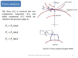


The document is a presentation on spur gears, detailing their design and applications in mechanical engineering. It covers concepts such as gear terminology, load analysis, tooth failure modes, and the advantages and disadvantages of spur gears, with examples of their applications in various industries. The presentation concludes with an emphasis on the vital role of spur gears in machinery and technical sectors.


![74676371-Coagulation-and-Flocculation[1].ppt](https://cdn.slidesharecdn.com/ss_thumbnails/74676371-coagulation-and-flocculation1-260116154109-a3cbf55e-thumbnail.jpg?width=640&height=640&fit=bounds)


