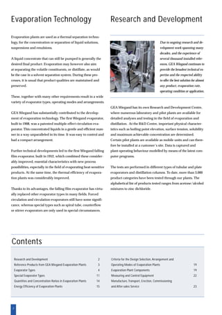
The document discusses GEA Wiegand's research and development center for evaporation technology. The R&D center contains numerous laboratory and pilot plants used to test over 3,000 product categories in different evaporator types. Certain pilot plants can be installed at customer sites. Data is collected and plant behavior is modeled using computer programs.

![14
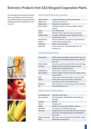
Quantities and Concentration Ratios
in Evaporation Plants
To calculate continuous evaporation processes, mass
flow rates rather than volumetric quantities are used.
The unit kg/hr is used for A, B and C. The ratios
indicated above do not change.
A C
B
Initial concentration cA
of the product flow A kg/hr
cA
cB
Evaporated product, concentrate
Final concentration cB
of concentrate flow B kg/hr
The evaporation ratio is a measure for
the concentration process:e The evaporation ratio can also be defined as the ratio of the
initial and final concentrations (% weight dry substance).
Part of the solvent (C), is evaporated from the
product flow (A). The residual amount (B), is
the evaporated product (concentrate):
A = B + C
e = A = cB
B cA
The evaporated quantity C, can therefore
be defined as the difference between the
quantity of thin solution and concentrate:
C = A – B
Vapour flow C [kg/hr]: Evaporated water,
solvent
Given
Quantity A to be
evaporated
Formula
C = A ·
e – 1
e
B = A ·
1
e
If the solvent is evaporated from thin solution A at an even rate, the
concentration rises slowly at first, but rises increasingly rapidly to the
theoretical maximum. At this point, no more solvent would be left in
the solution. The lower the initial concentration cA, the steeper the
increase of the concentration curve. This relationship is essential for the
control of evaporation plants, and in cases of high evaporation ratios,
for the separation of the evaporation process into pre-evaporation and
high concentration steps.
If the concentrations or the evaporation ratio is known,
the quantities can be calculated using the formulae in the
table below:
Left: Increase of final concentration during the evaporation from
solutions at different initial concentrations
Required
C
B](https://image.slidesharecdn.com/geaevaporation-technologybrochureentcm11-16319-190815072050/85/Gea-evaporation-technology-brochure_en_tcm11-16319-14-320.jpg)