
Recommended
More Related Content
What's hot
What's hot (20)
Similar to Fundamentals of gis
Similar to Fundamentals of gis (20)
Recently uploaded
Recently uploaded (20)
Fundamentals of gis
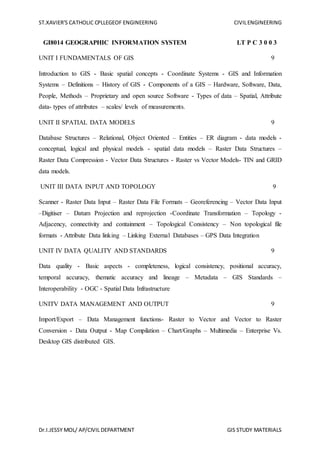
- 1. ST.XAVIER’S CATHOLIC CPLLEGEOF ENGINEERING CIVILENGINEERING Dr.I.JESSY MOL/ AP/CIVIL DEPARTMENT GIS STUDY MATERIALS GI8014 GEOGRAPHIC INFORMATION SYSTEM LT P C 3 0 0 3 UNIT I FUNDAMENTALS OF GIS 9 Introduction to GIS - Basic spatial concepts - Coordinate Systems - GIS and Information Systems – Definitions – History of GIS - Components of a GIS – Hardware, Software, Data, People, Methods – Proprietary and open source Software - Types of data – Spatial, Attribute data- types of attributes – scales/ levels of measurements. UNIT II SPATIAL DATA MODELS 9 Database Structures – Relational, Object Oriented – Entities – ER diagram - data models - conceptual, logical and physical models - spatial data models – Raster Data Structures – Raster Data Compression - Vector Data Structures - Raster vs Vector Models- TIN and GRID data models. UNIT III DATA INPUT AND TOPOLOGY 9 Scanner - Raster Data Input – Raster Data File Formats – Georeferencing – Vector Data Input –Digitiser – Datum Projection and reprojection -Coordinate Transformation – Topology - Adjacency, connectivity and containment – Topological Consistency – Non topological file formats - Attribute Data linking – Linking External Databases – GPS Data Integration UNIT IV DATA QUALITY AND STANDARDS 9 Data quality - Basic aspects - completeness, logical consistency, positional accuracy, temporal accuracy, thematic accuracy and lineage – Metadata – GIS Standards – Interoperability - OGC - Spatial Data Infrastructure UNITV DATA MANAGEMENT AND OUTPUT 9 Import/Export – Data Management functions- Raster to Vector and Vector to Raster Conversion - Data Output - Map Compilation – Chart/Graphs – Multimedia – Enterprise Vs. Desktop GIS distributed GIS.
- 2. ST.XAVIER’S CATHOLIC CPLLEGEOF ENGINEERING CIVILENGINEERING Dr.I.JESSY MOL/ AP/CIVIL DEPARTMENT GIS STUDY MATERIALS GI8014 GEOGRAPHIC INFORMATION SYSTEM UNIT I FUNDAMENTALS OF GIS Geographic Information System (GIS) A computerized system designed to capture, store, manipulate, analyse, manage and present all types of geographically referenced data. Basic definition of GIS G (Geography) - a particular form of Information System applied to geographical data (location, co-ordinates, maps etc.) I (Information) S (System) is a set of processes, executed on raw data, to produce information which will be useful in decision-making Definitions of a GIS and the groups who find them useful A container of maps in digital form A computerised tool for solving geographical problems A mechanised inventory of geographically distributed features and facilities A tool for revealing what is otherwise invisible in geographical information A tool for performing operations on geographical data more efficiently A spatial decision support system HISTORY OF GIS The GIS history dates back to 1960 when computer based GIS have been used and their manual procedures were in life 100 years earlier or so. The initial developments originated in North America with the organizations such as US Bureau of the Census, The US Geological Survey and The Harvard Laboratory for computer graphics and Environmental Systems Research Institute (commercial). Canadian Geographic Information Systems (CGIS) in Canada, Natural Experimental Research Center (NREC), Department of Environment (DOE) and other notable organizations in U.K. were involved in early developments. The laboratory for Computer Graphics and Spatial Analysis of the Harvard Graduate School of Design and the State University of New York at Buffalo achieved worldwide recognition. Commercial agencies started to develop and offer GIS software. Among them were today’s market leaders ESRI, Intergraph, Laserscan, Autodesk etc. A sound and stable data structure to store and analyze map data became dominant in the early 1970’s. This has lead to the introduction of topology into GIS. Topology and the related graph theory proved to be effective and efficient tools to provide logically consistent
- 3. ST.XAVIER’S CATHOLIC CPLLEGEOF ENGINEERING CIVILENGINEERING Dr.I.JESSY MOL/ AP/CIVIL DEPARTMENT GIS STUDY MATERIALS two-dimensional data representations. Another significant breakthrough occurred with the introduction and spread of personal computers in 1980’s. It was possible to have a computer on the desk that was able to execute programs that previously could only be run on mainframe computers. At the same time minicomputers, and later, workstations became widely available. Relational database technology became the standard. Research on spatial data structures, indexing methods, and spatial databases made tremendous progress. The 1990’s can be characterized as a period of the breakthrough of object-orientation in system and database design, recognition of geoinformatics as a professional activity, and spatial information theory as the theoretical basis for GIS. Potentiality of GIS is realized in the recent past and now it has become popular among many users for a variety of applications. In India the major developments have happened during the last one decade with significant contribution coming from Department of Space emphasizing the GIS applications for Natural Resources Management. Notable among them are Natural Resource Information System (NRIS), Integrated Mission for Sustainable Development (IMSD) and Bio-diversity Characterization at National Level. IIRS is also playing a major role in GIS through education and training programs at the National and International level. Recently the commercial organizations in India have realized the importance of GIS for many applications like natural resource management, infrastructure development, facility management; business/market applications etc. and many GIS based projects according to the user organization requirements were developed. GIS OBJECTIVES • Maximize the efficiency of planning and decision making • Provide efficient means for data distribution and handling • Elimination of redundant data base - minimize duplication • Capacity to integrate information from many sources • Complex analysis/query involving geographical referenced data to generate new information. GIS Process GIS Components
- 4. ST.XAVIER’S CATHOLIC CPLLEGEOF ENGINEERING CIVILENGINEERING Dr.I.JESSY MOL/ AP/CIVIL DEPARTMENT GIS STUDY MATERIALS Five key components of GIS: 1. Hardware 2. Software 3. Data 4. People 5. Method 1. Hardware The type of hardware determines, to an extent, the speed at which a GIS will operate. Additionally, it may influence the type of software used. To a small degree, it may influence the types/ personalities of the people working with the GIS. Input Devices, Scanners, Digitizers, Tape drivers, CD Keyboard, Graphic Monitor, Output Devices, Plotters, Printers etc. 2. Software It encompasses not only to the GIS package, but all the software used for databases, drawings, statistics, and imaging. The functionality of the software used to manage the GIS determines the type of problems that the GIS may be used to solve.The software used must match the needs and skills of the end user. Popular GIS Software Vector- Raster- (Clark Univ.) 3. Data Data is the information used within a GIS. Since a GIS often incorporates data from multiple sources, its accuracy defines the quality of the GIS. GIS quality determines the types of questions and problems that may be asked of the GIS 4. People Are the most important part of a GIS, define and develop the procedures used by a GIS, can overcome shortcoming of the other 4 elements (data, software, hardware, procedure), but not vice-versa 5. Method The procedures used to input, analyze, and query data determine the quality and validity of the final product. Buffering, models, topology Main functions of GIS 1. Data Capturing: digitising, Scanning, importing, manual data entry. 2. Data storage and management: database design, data integration 3. Data manipulation/ editing: cleaning and editing of data, dissolving boundaries, layering, georeferencing. 4. Data display: display of spatial and attribute data.
- 5. ST.XAVIER’S CATHOLIC CPLLEGEOF ENGINEERING CIVILENGINEERING Dr.I.JESSY MOL/ AP/CIVIL DEPARTMENT GIS STUDY MATERIALS Data Manipulation and analysis Spatial analysis Network analysis Buffering Corridor analysis Proximity analysis Boolean analysis, etc. Application of GIS GIS used in multiple disciplines Agriculture, Archaeology, Architecture/Landscape Arch., Business, Computer Science, Environmental Science, Engineering, Journalism , Military Science, Natural Resource Management, Geography, Geology, Meteorology, Oceanography , Law Enforcement , Public Health, History Sociology, Urban/Regional Planning SUPPORTING TECHNOLOGIES AND DISCIPLINES Geography: understanding the world and man’s place in it Cartography-art of map making: display of spatial information Remote Sensing: images from space and air Photogrammetry: accurate measurement from photographs Surveying: high quality positional data Geodesy- shape of the earth: accurate positional data (control points) Statistics: GIS models are often statistical in nature Computer Science: e.g. CAD, database management Math: especially geometry and graph theory Why a GIS Old Records/maps are poorly maintained Poorly Updated Inaccurate No Sharing No data retrieval service for maps Benefits of GIS Once a GIS is implemented, following benefits are expected: Better Maintained data Standard format Easy revision, Easy updation
- 6. ST.XAVIER’S CATHOLIC CPLLEGEOF ENGINEERING CIVILENGINEERING Dr.I.JESSY MOL/ AP/CIVIL DEPARTMENT GIS STUDY MATERIALS Easy Units conversion Easy to share Easier to search, analyze and represent Many value added products Enhance productivity of staff Time and Money saved Better Decision making Examples of geographical problems Government: where to locate public facilities (e.g. schools, hospitals and police stations)? Transportation: where to build the new highway that serves most critical bottleneck of the road network? Commercial: where to build new shops or good distribution centres that make most cost effective services? Travelers: where am I and how can I travel from Madurai to kanyakumari? Country park management: where to locate ring roads in Nagercoil that provide the best scenery for driving at different levels with the minimum impact on the environment? BASIC FUNCTIONS OF GIS • Data Acquisition And Pre-processing • Digitizing • Editing • Topology Building • Projection • Attribution ADVANTAGES OF GIS • Though collection of data is difficult once it is collected, it can be stored safely in digital form (in computer) forever without damage, which usually happens to our maps. • Once if a map is prepared accurately it can be printed in any scale without any redrawing. • Large scale maps at smaller units (Beats) level can be joined for creating maps at divisions or district level, very accurately within few minutes. • Changes can be incorporated very easily in computer and it doesn’t require any redrawing.
- 7. ST.XAVIER’S CATHOLIC CPLLEGEOF ENGINEERING CIVILENGINEERING Dr.I.JESSY MOL/ AP/CIVIL DEPARTMENT GIS STUDY MATERIALS • Same map can be generated even after 100s of years later. • New things can be known after overlay of different themes and a new types of maps can be generated. • Work can be done faster than manually. • The work of decision makers and end users will become easier. Limitations of GIS □ Data are expensive □ Shows spatial relationships but does not provide absolute solutions □ Origins in the Earth sciences and computer science. □ Solutions may not be appropriate for humanities research Geographic Coordinate Systems Geography – The study of where features are located on the Earth’s surface. Georeferencing / Geocoding – The process of assigning geographic coordinates to features to represent their location. Types of Coordinate Systems (1) Global Cartesian coordinates (x,y,z) for the whole earth (2) Geographic coordinates (f, l, z) (3) Projected coordinates (x, y, z) on a local area of the earth’s surface The z-coordinate in (1) and (3) is defined geometrically; in (2) the z-coordinate is defined gravitationally Introduction to Open Source GIS What is Open Source SW? Open source SW(OSS) is the computer SW that is available in source code form under certain licenses. Users of OSS are permitted to use, copy, study, change, improve and even redistribute those OSS freely. ‘Free’ does not mean ‘Free of Charge’ but ‘Freedom’ or ‘Liberty’ Benefits of Open Source SW Latitude Longitude - Represent exact positions on the Earth - 42.3216, - 71.089118
- 8. ST.XAVIER’S CATHOLIC CPLLEGEOF ENGINEERING CIVILENGINEERING Dr.I.JESSY MOL/ AP/CIVIL DEPARTMENT GIS STUDY MATERIALS Empower people, save money, save resources, increase stability, access to source code, access to skilled community of developers 1. Technological Aspects Rapid development of high- class SW Increased stability by skilled community review Reduce technological gap to leading proprietary SW company Internalize outside SW developer resources 2. Economic Aspects Very low adoption cost Reduce SW development cost Easy to customize Reuse successful story 3. Business Aspects Extend company’s products portfolio Open up new market by providing diversified services & products Improve brand image of company 4. Other Aspects Reduce energy Self- satisfaction Help society Reasons Why Select Open Source 1. Quality 2. Security 3. Ease of deployment 4. Source code access Open Source GIS • FOSS4G : Free Open Source Software for Geo-Spatial • GeoFOSS : Geospatial Free Open Source Software •
- 9. ST.XAVIER’S CATHOLIC CPLLEGEOF ENGINEERING CIVILENGINEERING Dr.I.JESSY MOL/ AP/CIVIL DEPARTMENT GIS STUDY MATERIALS Why Open Source GIS? Necessity Want to meet lots of needs of GIS from public sectors Want More with Less!! Want to replicate other people & institution’s experience Want to manage & modify the system by ourselves Advantages of open source software 1. Advance of Open Source GIS • Open Source GIS is now comparable with commercial proprietary GIS • Open Source GIS is now actively adopted & used all around the world 2. Cost Reduction • Open Source GIS is basically free. • The price of commercial Open Source GIS is lower than proprietary one 3. Interoperability • Almost all the Open Source GIS is compliant with OGC standards • Open Source GIS can be used with existing proprietary GIS 4. Opened Source Code • Anybody can modify & upgrade the system from the source code level • Can easily replicate or migrate success cases to their system 5. Collaboration based SW • Collaboration, sharing & community based SW development model • Source code will be managed by community not by company • Neutrality from specific technology or company • Anybody can join and contribute to Open Source GIS with OSGeo Open source software GRASS –U.S. Army Corps of Engineers, open source: a complete GIS o MapServer–Web-based mapping server, by the University of Minnesota. o Chameleon –Environments for building applications with MapServer. o GeoNetworkopen source –A catalogapplication to manage spatially referenced resources
- 10. ST.XAVIER’S CATHOLIC CPLLEGEOF ENGINEERING CIVILENGINEERING Dr.I.JESSY MOL/ AP/CIVIL DEPARTMENT GIS STUDY MATERIALS o ILWIS (Integrated Land and Water Information System) integrates image, vector and thematic data. o MapWindowGIS –Free, open source GIS desktop application and programming component. o PostGIS–Spatial extensions for the open source PostgreSQL database, allowing geospatial queries. o TerraView–GIS desktop that handles vector and raster data stored in a relational or geo-relational database. Proprietary Software Proprietary software is computer software licensed under exclusive legal right of the copyright holder The licensee is given the right to use the software under certain conditions, while restricted from other uses, such as modification, further distribution, or reverse engineering. Proponents of free and open source software use proprietary or non- free to describe software that is not free or open source. In the software industry, commercial software refers to software produced for sale, which is a related but distinct categorization. Limitations: License agreements do not override applicable copyright law or contract law. Provisions that conflict may not be enforceable The owner of proprietary software exercises certain exclusive rights over the software. The owner can restrict use, inspection of source code, modification of source code, and redistribution. Commercial or proprietary GIS software ESRI –Products include ArcView 3.x, ArcGIS, ArcSDE, ArcIMS, and ArcWeb services. GRAM++ GIS –Low-cost GIS software product developed by CSRE, IIT Bombay. Autodesk –MapGuideand other products that interface with its AutoCAD software package. Cadcorp–Developers of GIS software and OpenGISstandard Intergraph –GeoMedia, GeoMediaProfesional, GeoMediaWebMap ERDAS IMAGINE –GIS, Remote Sensing, and Photogrammetry software by Leica Geosystems Data Types in GIS The data in a GIS can be classified into two main categories: 1. Spatial data
- 11. ST.XAVIER’S CATHOLIC CPLLEGEOF ENGINEERING CIVILENGINEERING Dr.I.JESSY MOL/ AP/CIVIL DEPARTMENT GIS STUDY MATERIALS Describes the absolute and relative location of geographic features. 2. Attribute data or Non-spatial data Describes characteristics of the spatial features. These characteristics can be quantitative and/or qualitative in nature. Attributes Attributes can be numeric or alfa numeric data that is assigned to a point, line or area spatial features Example Attributes… Stand ID, Compartment no, Vegetation type, Name of the Forest Block, Type of Road etc., Eg.) Description or characteristic of a feature • Possible attributes for the feature Tree – Height – Diameter – Species – Condition – Age The value given to an attribute • Possible values for the attributes of a Tree feature • Height = 15m • Diameter= 0.75m • Species= Oak • Condition= Good • Age= 8 years Attribute Model Types Tabular Model Hierarchical Model Relational Model Network Model Object-Oriented Model Measurement and Scaling Measurement means assigning numbers or other symbols to characteristics of objects according to certain pre-specified rules.
- 12. ST.XAVIER’S CATHOLIC CPLLEGEOF ENGINEERING CIVILENGINEERING Dr.I.JESSY MOL/ AP/CIVIL DEPARTMENT GIS STUDY MATERIALS The rules for assigning numbers should be standardized and applied uniformly. Rules must not change over objects or time. Scales of measurement include: 1. Nominal 2. Ordinal 3. Interval 4. Ratio The scale determines the amount of information ccontained in the data. The scale indicates the data summarization and statistical analyses that are most appropriate. 1. Nominal Data are labels or names used to identify an attribute of the element. A nonnumeric label or numeric code may be used. Example: Students of a university are classified by the dorm that they live in using a nonnumeric label such as Farley, Keenan, Zahm, Breen-Phillips, and so on. A numeric code can be used for the school variable (e.g. 1: Farley, 2: Keenan, 3: Zahm, and so on). 2. Ordinal The data have the properties of nominal data and the order or rank of the data is meaningful. A nonnumeric label or numeric code may be used. Example: Students of a university are classified by their class standing using a nonnumeric label such as freshman, Sophomore, Junior, or Senior. A numeric code can be used for the class standing variable (e.g. 1 denotes freshman, 2 denotes Sophomore, and so on). 3. Interval The data have the properties of ordinal data, and the interval between observations is expressed in terms of a fixed unit of measure. Example: Average Starting Salary Offer 2003 Economics/Finance: $40,084 History: $32,108 Psychology: $27,454 Econ & Finance majors earn $7,976 more than History majors and $12,630 more than Psychology majors. 4. Ratio The data have all the properties of interval data and the ratio of two values is meaningful. Variables such as distance, height, weight, and time use the ratio scale. This scale must contain a zero value that indicates that nothing exists for the variable at the zero point.
- 13. ST.XAVIER’S CATHOLIC CPLLEGEOF ENGINEERING CIVILENGINEERING Dr.I.JESSY MOL/ AP/CIVIL DEPARTMENT GIS STUDY MATERIALS Example: Econ & Finance majors salaries are 1.24 times History major salaries and are 1.46 times Psychology major salaries Primary Scales of Measurement Nominal Numbers Assigned to Runners Ordinal Rank Order of Winners Third place second place First place Interval Performance Rating on a 0 to 10 Scale 8.2 9.2 9.6 Ratio Time to Finish in Seconds 15.2 14.1 13.4 Scale Basic Characteristics Common Examples Marketing Examples Nominal Numbers identify & classify objects Social Security nos., numbering of football players Brand nos., store types Ordinal Nos. indicate the relative positions of objects but not the magnitude of differences between them Quality rankings, rankings of teams in a tournament Preference rankings, market position, social class Interval Differences between objects Temperature (Fahrenheit) Attitudes, opinions, index Ratio Zero point is fixed, ratios of scale values can be compared Length, weight Age, sales, income, costs What Is Level of Measurement? The relationship of the values that are assigned to the attributes for a variable Variables Party Affilitation Attributes Party Affiliation Republican Independent Democrat
- 14. ST.XAVIER’S CATHOLIC CPLLEGEOF ENGINEERING CIVILENGINEERING Dr.I.JESSY MOL/ AP/CIVIL DEPARTMENT GIS STUDY MATERIALS Values 1 2 3 Relationship Why Is Level of Measurement Important? Helps you decide what statistical analysis is appropriate on the values that were assigned Helps you decide how to interpret the data from that variable Nominal Measurement The values “name” the attribute uniquely. The value does not imply any ordering of the cases, for example, jersey numbers in football. Even though player 32 has higher number than player 19, you can’t say from the data that he’s greater than or more than the other. Ordinal Measurement When attributes can be rank-ordered… Distances between attributes do not have any meaning, for example, code Educational Attainment as 0=less than H.S.; 1=some H.S.; 2=H.S. degree; 3=some college; 4=college degree; 5=post college Is the distance from 0 to 1 the same as 3 to 4? Interval Measurement When distance between attributes has meaning, for example, temperature (in Fahrenheit) -- distance from 30-40 is same as distance from 70-80. Note that ratios don’t make any sense -- 80 degrees is not twice as hot as 40 degrees (although the attribute values are). Ratio Measurement Has an absolute zero that is meaningful Can construct a meaningful ratio (fraction), for example, number of clients in past six months It is meaningful to say that “...we had twice as many clients in this period as we did in the previous six months. Continuous and Discrete Variables A continuous variable has an infinite number of possible values between any two points on the measurement scale. For example, mouse weight will have an infinite number of possible values between 25 grams and 26 grams because one could always add extra decimal places to the measurement. A discrete variable on the other hand can only take on a limited number of values. By their nature, all categorical variables are discrete, but so are many variables measured on ratio scales. One very important type of discrete variable measured on a ratio scale is a count
- 15. ST.XAVIER’S CATHOLIC CPLLEGEOF ENGINEERING CIVILENGINEERING Dr.I.JESSY MOL/ AP/CIVIL DEPARTMENT GIS STUDY MATERIALS such as the number of pups in a rat litter or number of correct responses on memory task. Counts are always positive integers. UNIT II SPATIAL DATA MODELS Database Management System (DBMS)
- 16. ST.XAVIER’S CATHOLIC CPLLEGEOF ENGINEERING CIVILENGINEERING Dr.I.JESSY MOL/ AP/CIVIL DEPARTMENT GIS STUDY MATERIALS What is a database? A database is any organized collection of data. Some examples: – a telephone book – T.V. Guide – airline reservation system – motor vehicle registration records – files on your computer hard drive. Features of a DBMS Database Management Systems provide features to maintain database: – Data independence - It refers to the immunity of user applications to make changes in the definition and organization of data. – Integrity and security - refers to maintaining and assuring the accuracy and consistency of data over its entire life-cycle. – Concurrency control - ensures that correct results for concurrent operations are generated, while getting those results as quickly as possible. – Backup and recovery – Provides a language for the creation and querying of the database. – A language for writing application programs DBMS Key characteristics of DBMS are: • performance, • store large volume of database, • share data (access), • provide security (authorization), • remove redundancy (normalization) • provide concurrent access (different users at the same time). Why we need database? Without database GIS is cartography (electronic map) No database No spatial analysis Types of database models
- 17. ST.XAVIER’S CATHOLIC CPLLEGEOF ENGINEERING CIVILENGINEERING Dr.I.JESSY MOL/ AP/CIVIL DEPARTMENT GIS STUDY MATERIALS Data model is a collection of conceptual tools for describing data, data relationship, and consistency constraints. There are mainly three types of models • Object-based logical models Are used to describe data at the conceptual and view level. Example of these the Entity- Relationship model and object-oriented model • Record-based logical models Are used to describe data at the conceptual and view level. Example of these are: Network model, Hierarchical model, and relational model. • Physical data models Are used to describe data at the physical level (bytes and words). It is mainly deal with hardware. Object oriented Model The basic unit that an object-oriented (OO-DBMS) manages is the object. It is based on four basic concepts: • Classification: Mapping of several objects (instances) to common class. • Generalization: Group several classes which have the same properties in common (roads, railway)-transportation network. • Association: Relation between similar objects is considered a higher level set object. • Aggregation: Objects which consist of several other objects (Composed objects). • OO model uses objects rather than records to manage data • An object has associated with it a set of variables that contain the data for the object, a set of messages to which the object respond, and a method which response to the message. • A geographic data handling systems employ this model are: TIGRIS, DAPLEX, and PROBE • It is application in GIS is recommended • For example student can be a superclass. First and second year student may represented by a classes that are specialization of a student class variables and methods specific to first year students are associated with fist year student class. • Variables and methods that apply both to first and second year students are associated with student class. • The variables associated with each class may be: Student: Name, ID, address First year student: Subject Second year student: Practical course
- 18. ST.XAVIER’S CATHOLIC CPLLEGEOF ENGINEERING CIVILENGINEERING Dr.I.JESSY MOL/ AP/CIVIL DEPARTMENT GIS STUDY MATERIALS Relational model • A relational database consists of a collection of tables, each of which is assigned a unique name. • Examples of RDBMS are Oracle, Informix, and Sybase. Reasons to use Relational Model • Independence of the physical data storage and logical database structure. • Variable and easy access to all data. • Flexible in database design. i.e complex objects are expressed as simple tables and relationships. • Applying relational design methods reduces data redundancy (Normalization) and storage requirements. Aspects of an RDBMS • Structures: Well defined objects • Operations: Clearly defined actions • Integrity Rules: Rules that control which operations are allowed on the data and structures of the database Relational Database Terminology • Each table contains the data for a single entity. • Each instance of an entity is a row/record/tuple in the table. This is a specific instance of the entity. • Columns contain attributes/fields that describe the entity. – Attributes in a column must be from the same domain (text, integer, date). – An attribute may have a range (e.g.; 0 ≤ integers ≤ 100) – Column order has no significance. • Tables are related through keys. Components of a Relational Database – Table: collection of rows all containing the same columns. – Row: Horizontal components of a table. Consists of values for each column. Each row is equivalent to a record. – Column: Vertical component of a table. Each column in the record is often referred to as a field. Relational Database Rules – Each column in a table must be unique
- 19. ST.XAVIER’S CATHOLIC CPLLEGEOF ENGINEERING CIVILENGINEERING Dr.I.JESSY MOL/ AP/CIVIL DEPARTMENT GIS STUDY MATERIALS – The order of the rows in a table is not meaningful – The order of the columns in a table is not meaningful – All data in a column must be the same type – Every table has a primary key, each column in the primary key must have a value Primary Key and Foreign Key – Relational database use primary keys and foreign keys to allow mapping of information from one table to another. – A foreign key is column or group of columns in a table whose value matches those of the primary key of another table. – Values in primary key column must be unique e.g. social security number (SSN). Relationships between Tables • One-to-One • One-to-Many • Many-to-One • Many-to-Many
- 20. ST.XAVIER’S CATHOLIC CPLLEGEOF ENGINEERING CIVILENGINEERING Dr.I.JESSY MOL/ AP/CIVIL DEPARTMENT GIS STUDY MATERIALS
- 21. ST.XAVIER’S CATHOLIC CPLLEGEOF ENGINEERING CIVILENGINEERING Dr.I.JESSY MOL/ AP/CIVIL DEPARTMENT GIS STUDY MATERIALS Entity • Has its own identity that distinguishes it from other entities. – Examples: • Person: PROFESSOR, STUDENT • Place: STORE, UNIVERSITY • Object: MACHINE, BUILDING • Event: SALE, REGISTRATION • Concept: ACCOUNT, COURSE Entity-Relationship (E-R) model • It is based on simulation of the real world which consists of basic objects called entities and relationship among these objects. • The overall logical data structure of a database can be expressed graphically by an E- R diagram. Which consists of rectangle (entity), ellipse (attribute), diamond(relationship), and lines. • Rectangles represent entity sets. • Diamonds represent relationship sets. • Lines link attributes to entity sets and entity sets to relationship sets. • Ellipses represent attributes • Double ellipses represent multivalued attributes.
- 22. ST.XAVIER’S CATHOLIC CPLLEGEOF ENGINEERING CIVILENGINEERING Dr.I.JESSY MOL/ AP/CIVIL DEPARTMENT GIS STUDY MATERIALS Attributes • Each Entity has a set of Attributes • Attribute is a property or characteristic of an entity that is of interest to the organization. Example: STUDENT: Student_ID, Student_Name, Phone_Number, Major Relationships • Relationships are associations between one or more entity types. • Are the “glue” that holds together components of an E-R model. • The degree of a relationship = is the number of entity types that participate in a relationship. There are 3 common relationships: 1. Unary (degree one) 2. binary (degree two) 3. Ternary (degree three) Aggregation
- 23. ST.XAVIER’S CATHOLIC CPLLEGEOF ENGINEERING CIVILENGINEERING Dr.I.JESSY MOL/ AP/CIVIL DEPARTMENT GIS STUDY MATERIALS Aggregation is an abstraction through which relationships are treated as higher-level entities i.e. express relationships among relationships Generalization • In E-R diagram generalization is depicted through a triangle labeled ISA (is a). • The attribute of higher level entity are said to be inherited by lower level entity. • e.g. both saving and checking account inherit the attributes of account • Relationship types may be
- 24. ST.XAVIER’S CATHOLIC CPLLEGEOF ENGINEERING CIVILENGINEERING Dr.I.JESSY MOL/ AP/CIVIL DEPARTMENT GIS STUDY MATERIALS – many-to-many: e.g., a town may have many road, which in turn may pass through many towns – many-to-one: e.g., a town may have many cinemas, but a cinema can be located in at most one town – one-to-one: e.g., a cinema may have one manager who manages only one cinema • These constraints constitute cardinality conditions Starting an ERD 1. Define the Entities. 2. Define the Relationships. 3. Add attributes to the relationships. 4. Add cardinality to the relationships. 5. Don’t forget to use proper naming conventions and symbol representation. What is Data Model Data Model is a collection of conceptual tools for describing data, data relationships, data semantics and consistency constraint. u A data model is a conceptual representation of data structures required for data base and is very powerful in expressing and communicating the business requirements. u A data model visually represents the nature of data, business rules governing the data, and how it will be organized in the database. A data model provides a way to describe the design of a database at the physical, logical and view levels. Different Data Models • Conceptual: describes WHAT the system contains. • Logical: describes HOW the system will be implemented, regardless of the DBMS. • Physical: describes HOW the system will be implemented using a specific DBMS. There are mainly three different types of data models: 1. Conceptual: This Data Model defines WHAT the system contains. This model is typically created by Business stakeholders and Data Architects. The purpose is to organize, scope and define business concepts and rules. 2. Logical: Defines HOW the system should be implemented regardless of the DBMS. This model is typically created by Data Architects and Business Analysts. The purpose is to developed technical map of rules and data structures. 3. Physical: This Data Model describes HOW the system will be implemented using a specific DBMS system. This model is typically created by DBA and developers. The purpose is actual implementation of the database.
- 25. ST.XAVIER’S CATHOLIC CPLLEGEOF ENGINEERING CIVILENGINEERING Dr.I.JESSY MOL/ AP/CIVIL DEPARTMENT GIS STUDY MATERIALS Conceptual data model • A conceptual data model provides a model of the proposed system that is independent of implementation details • An effective conceptual model will – provide a means for communication between analysts, designers and users – aid the design of the system – provide basic reference material for implemented system The Conceptual Model • Represents global view of the entire database. • Representation of data as viewed by the entire organization. • Basis for identification and high-level description of main data objects, avoiding details. • Most widely used conceptual model is the entity relationship (ER) model. • Provides a relatively easily understood macro level view of data environment • Independent of both software and hardware • Does not depend on the DBMS software used to implement the model • Does not depend on the hardware used in the implementation of the model • Changes in either hardware or DBMS software have no effect on the database design at the conceptual level The Physical Model • Operates at lowest level of abstraction, describing the way data are saved on storage media such as disks or tapes. • Software and hardware dependent.
- 26. ST.XAVIER’S CATHOLIC CPLLEGEOF ENGINEERING CIVILENGINEERING Dr.I.JESSY MOL/ AP/CIVIL DEPARTMENT GIS STUDY MATERIALS • Requires that database designers have a detailed knowledge of the hardware and software used to implement database design Data Model Concepts • Data model is the objects in a spatial database plus the relationships among them. • Coordinates are used to define the spatial location and extent of geographic objects. • Attribute/non-spatial data are linked with coordinate data to define each spatial object in the spatial database • Spatial objects are represented in two most common spatial data models. They are Raster and Vector data models. • Spatial data models begin with conceptualization, how you will represent the real world phenomena or entities, E.g. a road can be represented as lines; river as line or polygon; city and towns as point or polygon, etc. • The road to include the road type (e.g.: highway, street, etc. or gravel, paved/ asphalted, etc.); width of road, • There are two main data models or conceptualizations used for spatial data: Vector data model and Raster data model • Vector data model use discrete objects such as point, lines and polygons to represent the geometry of the real-world entities, discrete entities. E.g. a road, river, city and towns, lakes or wetlands, farm land, etc. • Raster data model represents continuous phenomena that may change continuously across a region, E.g. Elevation, rainfall, temperature, soil moisture, etc. • Raster model uses grid cells for representing continuous phenomena
- 27. ST.XAVIER’S CATHOLIC CPLLEGEOF ENGINEERING CIVILENGINEERING Dr.I.JESSY MOL/ AP/CIVIL DEPARTMENT GIS STUDY MATERIALS
- 28. ST.XAVIER’S CATHOLIC CPLLEGEOF ENGINEERING CIVILENGINEERING Dr.I.JESSY MOL/ AP/CIVIL DEPARTMENT GIS STUDY MATERIALS Data models in GIS RASTER DATA MODEL VECTOR DATA MODEL TRIANGULATED IRREGULAR NETWORK MODEL(TIN) DIGITAL ELEVATION MODEL (DEM) NETWORK MODELS RasterData Model RasterData Model defines the world as a regular set of cells in a uniform grid pattern • Cells are square and evenly spaced in the x and y directions • Each cell represent attribute values and cell location of phenomena or entities • Cell dimension specifies the length and width of the cell in surface units. • Raster data models represent continuous phenomena or spatial features • E.g. Elevation/DEM, bathymetry, precipitation, slope, etc. • Raster data model may also be used to represent discrete data • E.g. Land cover: forest, wetlands, urban areas Characteristics: • Rectangular grid of square cells • Shape of discrete polygonal features generalized by cells • Continuous (surface) data represented easily • Simple data structure Cell Size of Raster Data • The level of detail represented by a raster is often dependent on the cell (pixel) size or spatial resolution of the raster. • The cell must be small enough to capture the required detail but large enough so computer storage and analysis can be performed efficiently. Smaller cell size Larger cell size Higher resolution Lower resolution Lower feature spatial accuracy Higher feature spatial accuracy. Faster display Slower display Faster processing Slower processing Smaller file size Large file size Advantages of Raster It is a simple data structure.
- 29. ST.XAVIER’S CATHOLIC CPLLEGEOF ENGINEERING CIVILENGINEERING Dr.I.JESSY MOL/ AP/CIVIL DEPARTMENT GIS STUDY MATERIALS It has the ability to represent continuous surfaces and perform surface analysis. The ability to uniformly store points, lines, polygons and surfaces. The ability to perform fast overlays with complex datasets. Cheaper technology Disadvantages of Raster There can be spatial inaccuracies due to limits imposed by raster dataset cell dimension. Raster datasets are potentially very large. Resolution increases as the size of cells decreases. Accordingly cost and disk space used also increases. There is also a loss of precision that accompanies restructuring data to a regularly spaced raster cell boundary. Projection transformation is difficult May lose information due to generalization Vector Data Model There are three basic types of vector objects: points, lines and polygons Vector data model uses sets of coordinates and associated attribute data to define discrete objects. Point objects in spatial database represent location of entities considered to have no dimension, Simplest type of spatial objects E.g. wells, sampling points, poles, telephone towers, etc. Line objects are used to represent linear features using ordered set of coordinate pairs E.g. infrastructure networks (transport networks: highways, railroads, etc.) ; utility networks: (gas, electric, telephone, water, etc. ); airline networks: hubs and routes, etc.); natural networks such as river channels Polygon objects in spatial database represent entities which covers an area E.g. lakes, Buildings, parcels, etc. Boundaries may be defined by natural phenomena (e.g. lake), or by man made features (e.g census tracts, neighborhoods) E.g. Land cover data: forest, wetlands, urban areas, etc. Soil data – soil types
- 30. ST.XAVIER’S CATHOLIC CPLLEGEOF ENGINEERING CIVILENGINEERING Dr.I.JESSY MOL/ AP/CIVIL DEPARTMENT GIS STUDY MATERIALS Vectors are graphical objects that have geometrical primitives such as points, lines and polygons to represent geographical entities in the computer graphics. A vector refers to a geometrical space which has a precise direction, length and shape Points, Lines and Polygons can be defined by the coordinate geometry. A vector spatial data model uses two-dimensional Cartesian (x, y) coordinate system to store the shape of a spatial entity. In vector world the point is the basic building block from which all spatial entities are constructed. The simplest spatial entity, the point, is represented by a single (x, y) coordinate pair. Line and area entities are constructed by connecting a series of points into chains and polygons.
- 31. ST.XAVIER’S CATHOLIC CPLLEGEOF ENGINEERING CIVILENGINEERING Dr.I.JESSY MOL/ AP/CIVIL DEPARTMENT GIS STUDY MATERIALS Point A point is a '0 ‘dimensional object and has only the property of location (x,y). Points can be used to Model features such as a well, building, power pole, sample location etc. Other names for a point are vertex, node, 0-cell. Line A line is a one-dimensional object that has the property of length. Lines can be used to represent road, streams, faults, dikes, marker beds, boundary, contacts etc. Lines are also called an edge, link, chain, arc, 1-cell Connected multiple lines are called polylines. Polygon Polygon features are made of one or more lines that enclose an area. A polygon is a two- dimensional object with properties of area and perimeter represented by a closed sequence of lines. A polygon can represent a city, geologic formation, dike, lake, river, etc. Advantages of Vector • Requires less disk storage space. • Efficient for topological relationship • Graphical output more closely resembles hand-drawn maps. • Easy to edit • Accurate map output • Efficient projection transformation • Good representation of reality
- 32. ST.XAVIER’S CATHOLIC CPLLEGEOF ENGINEERING CIVILENGINEERING Dr.I.JESSY MOL/ AP/CIVIL DEPARTMENT GIS STUDY MATERIALS • Topology can be described in a network Disadvantages of Vector • Complex data structure. • Less compatibility with remotely sensed data. • Expensive software and hardware. • Not appropriate to represent continuous data. • Overlaying multiple vector are often time consuming. • Simulation may be difficult. • Some spatial analysis is difficult or impossible to perform Difference between Rasterand Vector Raster Vector It is a simple data structure. More complex datastructure. Overlay operations are easily and efficiently implemented. Overlay operations aremore High spatial variability is efficiently represented in a raster format. Difficult to implement. The raster format is more or less required for efficient manipulation and enhancement of digital images The representation of high spatial variability isinefficient. The raster data structure is Vector provides amore Less compact. Compact datastructure. Topological relationships are more difficult to represent. Provides efficient encoding of topology. GIS Data Models: Raster v. Vector “raster is faster but vector is corrector” Joseph Berry Raster data model Vector data model location is referenced by a grid cell in a rectangular array (matrix) location referenced by x,y coordinates, which can be linked to form lines and polygons attribute isrepresentedasa single value for that cell attributesreferencedthroughunique ID number to tables much data comes in this form much data comes in this form images from remote sensing (LANDSAT, SPOT) DIME and TIGER files from US Census best for continuous features: elevation temperature soil type land use best for features with discrete boundaries property lines political boundaries transportation
- 33. ST.XAVIER’S CATHOLIC CPLLEGEOF ENGINEERING CIVILENGINEERING Dr.I.JESSY MOL/ AP/CIVIL DEPARTMENT GIS STUDY MATERIALS Raster Data Structures – Raster data stored as an array of values • Georeferencing is implicit in the structure • Usually defined by one corner of the image and the cell size • Attributes are defined by the cell values (no character data!) • One attribute for each raster file Raster data structure refers to the method or format for storing raster data. The three common methods for storing raster data are: 1. Cell-by-Cell Encoding 2. Run Length Encoding 3. Quad Tree Cell-by-Cell Encoding The cell-by-cell encoding method provides the simplest raster data structure. A raster is stored as a matrix, and its cell values are written into a file by row and column. The cell-by-cell encoding method becomes inefficient if a raster contains many redundant cell values.
- 34. ST.XAVIER’S CATHOLIC CPLLEGEOF ENGINEERING CIVILENGINEERING Dr.I.JESSY MOL/ AP/CIVIL DEPARTMENT GIS STUDY MATERIALS Run- Length Encoding (RLE) The run length encoding method is a raster data structure that records the cell values by row and by group. For example, this method records the cell values in runs. Row 1, has two adjacent cells in columns 5 and 6 that are gray or have the value of 1. Row 1 is therefore encoded with one run, beginning in column 5 and ending in column 6. The same method is used to record other rows. Quad Tree The regional quad tree method divides a raster into a hierarchy of quadrants. The division stops when a quadrant is made of cells of the same value (gray or white). A quadrant that cannot be subdivided is called a leaf node. In the diagram, the quadrants are indexed spatially: 0 for NW, 1 for SW, 2 for SE, and 3 for NE. Using the spatial indexing method and the hierarchical quad tree structure, the gray cells can be coded as 02, 032, and so on.
- 35. ST.XAVIER’S CATHOLIC CPLLEGEOF ENGINEERING CIVILENGINEERING Dr.I.JESSY MOL/ AP/CIVIL DEPARTMENT GIS STUDY MATERIALS Raster Data Compression Data compression refers to the reduction of data volume. A variety of techniques are available for image compression. Compression techniques can be lossless or lossy. Lossless Compression: One type of data compression that allows the original image to be precisely reconstructed. Lossy Compression: One type of data compression that can achieve high compression ratios but cannot reconstruct fully the original image . LOSSLESS COMPRESSION • In lossless data compression, the integrity of the data is preserved. • The original data and the data after compression and decompression are exactly the same because, the compression and decompression algorithms are exact inverses of each other: no part of the data is lost in the process. • Redundant data is removed in compression and added during decompression. • Lossless compression methods are normally used when we cannot afford to lose any data. Run-length encoding • Run-length encoding is probably the simplest method of compression. • It can be used to compress data made of any combination of symbols. • It does not need to know the frequency of occurrence of symbols and can be very efficient if data is represented as 0s and 1s. • The general idea behind this method is to replace consecutive repeating occurrences of a symbol by one occurrence of the symbol followed by the number of occurrences. • The method can be even more efficient if the data uses only two symbols (for example 0 and 1).
- 36. ST.XAVIER’S CATHOLIC CPLLEGEOF ENGINEERING CIVILENGINEERING Dr.I.JESSY MOL/ AP/CIVIL DEPARTMENT GIS STUDY MATERIALS Huffman coding • Huffman coding assigns shorter codes to symbols that occur more frequently and longer codes to those that occur less frequently. • For example, imagine we have a text file that uses only five characters (A, B, C, D, E). • Before we can assign bit patterns to each character, we assign each character a weight based on its frequency of use. In this example, assume that the frequency of the characters is as shown in Table A character’s code is found by starting at the root and following the branches that lead to that character.
- 37. ST.XAVIER’S CATHOLIC CPLLEGEOF ENGINEERING CIVILENGINEERING Dr.I.JESSY MOL/ AP/CIVIL DEPARTMENT GIS STUDY MATERIALS Final tree and code Lempel Ziv encoding • Lempel Ziv (LZ) encoding is an example of a category of algorithms called dictionary-based encoding. • The idea is to create a dictionary (a table) of strings used during the communication session.
- 38. ST.XAVIER’S CATHOLIC CPLLEGEOF ENGINEERING CIVILENGINEERING Dr.I.JESSY MOL/ AP/CIVIL DEPARTMENT GIS STUDY MATERIALS LOSSY COMPRESSION METHODS These methods are cheaper—they take less time and space when it comes to sending millions of bits per second for images and video. Several methods have been developed using lossy compression techniques. JPEG (Joint Photographic Experts Group) encoding is used to compress pictures and graphics, MPEG (Moving Picture Experts Group) encoding is used to compress video, and MP3 (MPEG audio layer 3) for audio compression. Image compression – JPEG encoding In JPEG, a grayscale picture is divided into blocks of 8 × 8 pixel blocks to decrease the number of calculations because, as we will see shortly, the number of mathematical operations for each picture is the square of the number of units. JPEG grayscale example, 640 × 480 pixels The JPEG compression process Triangulated Irregular Network (TIN) TIN stands for Triangular Irregular Network, which is a vector approach to handling a digital elevation model. TIN’s are used to interpolate surfaces using multiple triangles. TIN’s are able to interpolate surfaces by selecting representative points that are usually data points. TIN’s connect these points to form a set of continuous and connected triangles. The data points consist of X, Y and Z values. The final result gives users a TIN surface.
- 39. ST.XAVIER’S CATHOLIC CPLLEGEOF ENGINEERING CIVILENGINEERING Dr.I.JESSY MOL/ AP/CIVIL DEPARTMENT GIS STUDY MATERIALS TIN Data Model Triangulated Irregular Network (TIN) is data model commonly used to represent terrain heights x, y, and z locations, used as measured points in TIN Result in TIN composed of nodes, lines and triangulated faces TIN used for digital elevation models (DEM) or digital terrain models (DTM) Very efficient way of representing topography Advantages of TIN TIN’s give researchers the ability to view 2.5D and 3D at an area that was interpolated from minimal data collection. Users can describe a surface at different levels of resolution based on the points that were collected. TIN interpolation gives GIS users greater analytical capabilities. TIN models are easy to create and use. They provide users a simplified model that represents collected data points. TIN users can also derive slope, aspect, elevation, contour lines, hillshades, etc. Disadvantages Analysis involving comparison with other layers difficult Different Types of TIN Methods and Processes Some of the most popular TIN methods include Natural Neighbour, Krigging, Spline, Nearest Neighbour and Inversed Distance Weighting. These TIN interpolation methods use mathematical algorithms in order to generate interpolated surfaces. Each of these methods will produce different types of surfaces. Components of a TIN • Nodes • Edges • Triangles • Hull • Topology
- 40. ST.XAVIER’S CATHOLIC CPLLEGEOF ENGINEERING CIVILENGINEERING Dr.I.JESSY MOL/ AP/CIVIL DEPARTMENT GIS STUDY MATERIALS Triangulated Irregular Networks (TIN) • A network of triangles connected together to create a 3D surface • Triangles do not cross • More complex than raster. • more efficient space-wise • Easily accommodates differing sample density • TIN preserves each measurement point Inputs for Creating a TIN • Hard breaklines define locations of abrupt surface change (e.g. streams, ridges, road kerbs, building footprints, dams) • Soft breaklines are used to ensure that known z values along a linear feature are maintained in the tin. Grid data structure Grid size is defined by extent, spacing and no data value information Number of rows, number of column Cell sizes (X and Y) Top, left , bottom and right coordinates Mass Points Soft Breaklines Hard Breaklines
- 41. ST.XAVIER’S CATHOLIC CPLLEGEOF ENGINEERING CIVILENGINEERING Dr.I.JESSY MOL/ AP/CIVIL DEPARTMENT GIS STUDY MATERIALS Points as Cells Line as a Sequence of Cells Polygon as a Zone of Cells NODATA Cells Grid Properties • Each Grid Cell holds one value even if it is empty. • A cell can hold an index standing for an attribute. • Cell resolution is given as its size on the ground. • Point and Lines move to the center of the cell. • Minimum line width is one cell. • Raster are easy to read and write, and easy to draw on the screen.
- 42. ST.XAVIER’S CATHOLIC CPLLEGEOF ENGINEERING CIVILENGINEERING Dr.I.JESSY MOL/ AP/CIVIL DEPARTMENT GIS STUDY MATERIALS UNIT III DATA INPUT AND TOPOLOGY Scanner • Copy data from a source, Scanners take paper and convert it into a bitmap • Types of scanners • Optical scanner • Bar code readers • Character and Mark recognition 2 Optical scanner • Convert text or drawings into machine readable format • Can be displayed, printed, or stored Types of optical scanners Flatbed scanner Source placed on glass surface Image scanned from below Portable scanner Handheld device that slides across source Flatbed scanner • If we talk about scanners, thus we mean usually flatbed scanner. • The scan documents (texts, photo, diagrams etc.) are put on a glass plate like a copier, under which a carriage with an exposure item and the read head moves. • Then the picture is scanned the picture information is entered by a CCD (Charge Couple Device). • CCDs are semiconductor chips, with an array of photo-sensitive cells, • Which are used for the transformation from electromagnetic waves of light into electrical signals. Types of Flatbed scanners • Sheetfed scanner use motorized rollers to feed the document across the scanning mechanism • Handheld scanner-portable device that requires users to pass the scanning element over the item to be scanned. Bar code readers • photoelectric scanner
- 43. ST.XAVIER’S CATHOLIC CPLLEGEOF ENGINEERING CIVILENGINEERING Dr.I.JESSY MOL/ AP/CIVIL DEPARTMENT GIS STUDY MATERIALS • Using Optical Recognition, a light beam scans the item and changes it into electrical impulses for processing Contain photoelectric cells that read bar codes • Read bar codes – Alternating black & white vertical bars – Universal Product Code (UPC) - Seen in grocery stores, retail stores Benefits Designed for business document capture Easier error recovery Ability to run the device within your application PC security is well established and controlled by IT Business rules can easily be forced on users at scan time Security/chain of custody File output size optimization Ability to handle larger batches of documents Even multiple batches at one time Overscan Rated performance across a variety of file types Issues Additional hardware to manage Capture Software training required Based on the basic constraints some other practical limitations of scanners should be identified. most companies or agencies cannot afford their own scanning device and therefore must send their maps to a private firm for scanning hard copy data may not be in a form that is viable for effective scanning, e.g. maps are of poor quality, or are in poor condition; geographic features may be too few on a single map to make it practical, often on busy maps a scanner may be unable to distinguish the features to be captured from the surrounding graphic information, e.g. dense contours with labels; with raster scanning there it is difficult to read unique labels (text) for a geographic feature effectively Scanning is much more expensive than manual digitizing, considering all the cost/performance issues. Advantages and Disadvantages of Scanning
- 44. ST.XAVIER’S CATHOLIC CPLLEGEOF ENGINEERING CIVILENGINEERING Dr.I.JESSY MOL/ AP/CIVIL DEPARTMENT GIS STUDY MATERIALS Advantages Scanned maps can be used as image backdrops for vector information. Clear base maps or original color separations can be vectorized relatively easily using raster-to-vector conversion software; Small-format scanners are relatively inexpensive and provide quick data capture. Disadvantages • Converting large maps with small format scanners requires tedious re-assembly of the individual parts; • Scanning large volumes of hard-copy maps will present challenges for file storage on many desktop computer systems • Despite recent advances in vectorization software, considerable manual editing and attribute labeling may still be required. Input of spatial data • Need to have tools to transform spatial data of various types into digital format • Data input is a major bottleneck in application of GIS technology. Costs of input often consume 80% or more of project costs • Many commercial GIS operations generate most of their revenue through data input • Data input is labor intensive, tedious, and error-prone • Essential to find ways to reduce costs and maximize accuracy • Need to automate the input process as much as possible, but: automated input cab create bigger editing problems later • Source documents (maps) may often have to be redrafted to meet rigid quality requirements of automated input • Sharing of digital data is one way around the input bottleneck. More and more spatial data is becoming available in digital form There are two methods for spatial data acquisition • Primary methods: Surveying, Photogrammetry, GPS, and Remote Sensing • Secondary methods: Digitization, Automatic line following, and scanning Modes of data input: Input Devices • Grid overlay • keyboard • Digitizer • Scanner
- 45. ST.XAVIER’S CATHOLIC CPLLEGEOF ENGINEERING CIVILENGINEERING Dr.I.JESSY MOL/ AP/CIVIL DEPARTMENT GIS STUDY MATERIALS • Data in digital format (Total station, digital photogrammetry, remote sensing, GPS) Grid overlay • Grid on clear material is overlaid on map • Identity of each cell in the grid is determined by what map features are in a particular cell • Number or code is assigned to each class of map features, and used to label cells in grid • After filling in the grid, numbers or codes are typed into the computer to produce a raster layer Keyboard • Keyboard entry (X,Y,Z), (Ø, , h), or angle and distance • Input through keyboard is time consuming, but it is more accurate • It is suitable for small areas i.e. when the number of points/lines/areas are limited • Because of its high accuracy, sometimes it is used in applications that need high quality e.g. cadastral mapping The input subsystem • Designed to transfer data into the GIS from external sources (attribute and map data) • Must allow for encoding in either raster or vector(TIN) • Must provide a means for spatial referencing (projections, Cartesian coordinate systems, etc.) • Must provide link between storage and editing subsystems (ensure input can be saved and any errors corrected) Methods of Raster Input • Presence/absence method: If object occurs in a cell (anywhere) it is recorded as present ( simplicity ) best method for coding points and lines • Centroid of cell method: Presence only recorded if object is at the center of the cell . Disadv. - Less simple, requires calculation of centroid, location of object relative to centroid. Generally restricted to raster encoding of polygons • Dominant type method: Commonly used for encoding polygons into raster format . Identified as present if it occupies more than 50% of the cell • Percent occurrence: Not only encodes presence/absence, but % occurrence (Urban/Rural) • Generally, each attribute is recorded as a separate coverage e.g., one grid of percent urban, one of percent rural, percent water, percent forest, etc.
- 46. ST.XAVIER’S CATHOLIC CPLLEGEOF ENGINEERING CIVILENGINEERING Dr.I.JESSY MOL/ AP/CIVIL DEPARTMENT GIS STUDY MATERIALS Raster Data File Formats • Raster data is stored in various formats; some of these include • BMP (Bitmap Image) • TIFF (Tag Index File Format)- a format for storing raster graphics images • JPEG/JPG (Joint Photographic Expert Group) • IMG (Image File Format) • GIF (Graphic Intercharge Format) • PSP (Portable Sony Play station) • CDR (Crash Data Retrieval) Common raster formats • TIFF = Tagged Image File Format, a format for storing raster graphics images • GeoTIFF • A public domain metadata standard which allows georeferencing information to be embedded within a TIFF file, such as −map projection −coordinate systems −Ellipsoids −Datum Methods of Vector Input • Manual digitizing, Registration marks • Location of nodes, • Building of topology • Correcting of digitizing errors • Transformation and projection • Adding attribute data
- 47. ST.XAVIER’S CATHOLIC CPLLEGEOF ENGINEERING CIVILENGINEERING Dr.I.JESSY MOL/ AP/CIVIL DEPARTMENT GIS STUDY MATERIALS • Checking the accuracy of attribute data Digitizing • Manual Digitizing – Digitizing is often tedious and tiring to the operators • Heads up Digitizing (old and new method) – In the old method, the operator traced map features on a transparency and attached this map to the computer screen – In the new method of heads-up digitizing, a scanned map image is used digitally to trace the outlines into a GIS layer Some of the common problems in digitizing paper maps are: • Paper maps are unstable; • each time the map is removed from the digitizing table, • The reference points must be re-entered when the map is affixed to the table again. • If the map has stretched or shrunk in the interim, the newly digitized points will be slightly off in their location Advantages and Disadvantages of Digitizing Advantages Digitizing is easy to learn and thus does not require expensive skilled labor; Attribute information can be added during the digitizing process; High accuracy can be achieved through manual digitizing; i.e., there is usually no loss of accuracy compared to the source map. Disadvantages • Digitizing is tedious possibly leading to operator fatigue and resulting quality problems which may require considerable post-processing; • Manual digitizing is quite slow; • In contrast to primary data collection using GPS or aerial photography, the accuracy of digitized maps is limited by the quality of the source material. GEOREFERENCING Proces of taking a digital image It could be an aerial photo, a scanned geologic map , or an picture of an topographic map. Adding geographic information to the image so that GIS or mapping software can ‘place’ the image in appropriate real world coordinate position.
- 48. ST.XAVIER’S CATHOLIC CPLLEGEOF ENGINEERING CIVILENGINEERING Dr.I.JESSY MOL/ AP/CIVIL DEPARTMENT GIS STUDY MATERIALS Geographical Concepts • Geodetic Datum: defines the position of the origin, scale, shape, and orientation of a 3-dimensional model of the earth. Example: WGS84. • Coordinate System: defines the “units of measure” of position with respect to the datum. Example: latitude, longitude in degrees, minutes, seconds Map Projections • Mathematical transformations of the 3-D model of the surface of the earth onto a 2-D map. • There are many (e.g., conical, cylindrical, azimuthal) - they all suffer from distortions (area, shape, distance, or direction), but some preserve areas or distances. • When measuring distances on paper maps, use an equal distance projection, if available, otherwise understand the implications. Types of map projection 1. CONICAL PROJECTIONS It can be visualized as a cone placed on the globe, tangent to it at some parallel. After projecting the graticule on to the cone, the cone is cut along one of the meridian and unfolded. Parallels appear as arcs with a pole and meridians as straight lines that converge to the same point. It can represent only one hemisphere, at a time, northern or southern. Suitable for representing middle latitudes. (a) Tangent: when the cone is tangent to only one of the parallel. (b) Secant: when the cone is not big enough to cover the curvature of earth, it intersects the earth twice at two parallels.
- 49. ST.XAVIER’S CATHOLIC CPLLEGEOF ENGINEERING CIVILENGINEERING Dr.I.JESSY MOL/ AP/CIVIL DEPARTMENT GIS STUDY MATERIALS 2. CYLINDIRICAL PROJECTIONS It can be visualized as a cylinder wrapped around the globe. Once the graticule is projected onto the cylinder, the cylinder is opened to get a grid like pattern of latitudes and longitudes. The longitudes (meridians) and latitudes (parallels) appear as straight lines Length of equator on the cylinder is equal to the length of the equator therefore is suitable equatorial regions. (a) Normal: when cylinder has line of tangency to the equator. It includes Equirectangular Projection, the Mercator projection, Lambert's Cylindrical Equal Area, Gall's Stereographic Cylindrical, and Miller cylindrical projection. (b) Transverse: when cylinder has line of tangency to the meridian. It includes the Cassini Projection, Transverse Mercator, Transverse cylindrical Equal Area Projection, and Modified Transverse Mercator. (c) Oblique: when cylinder has line of tangency to another point on the globe. It only consists of the Oblique Mercator projection. 3. Azimuthal/Zenithal Projection It can be visualized as a flat sheet of paper tangent to any point on the globe The sheet will have the tangent point as the centre of the circular map, where meridians passing through the centre are straight line and the parallels are seen as concentric circle. Suitable for showing polar areas (a) Equatorial zenithal: When the plane is tangent to a point on the equator.
- 50. ST.XAVIER’S CATHOLIC CPLLEGEOF ENGINEERING CIVILENGINEERING Dr.I.JESSY MOL/ AP/CIVIL DEPARTMENT GIS STUDY MATERIALS (b) Oblique zenithal: when the plane is tangent to a point between a pole and the equator. (c) Polar zenithal: when the plane is tangent to one of the poles. Projection Properties According to properties map projections can be classified as: Equal area projection: Also known as homolographic projections. The areas of different parts of earth are correctly represented by such projections. True shape projection: Also known as orthomorphic projections. The shapes of different parts of earth are correctly represented on these projections. True scale or equidistant projections: Projections that maintain correct scale are called true scale projections. However, no projection can maintain the correct scale throughout. Correct scale can only be maintained along some parallel or meridian. COORDINATE TRANSFORMATION Coordinate Transformation brings spatial data into an Earth-based map coordinate system using control points Source Source Transformed Control Points Used to transform data from digitizer coordinate system to map coordinate system We use two sets of control points
- 51. ST.XAVIER’S CATHOLIC CPLLEGEOF ENGINEERING CIVILENGINEERING Dr.I.JESSY MOL/ AP/CIVIL DEPARTMENT GIS STUDY MATERIALS • Digitizer control points • Map control points Control Point Criteria 1. Should provide highest feasible coordinate accuracy 2. Accuracy should be at least as good as desired overall positional accuracy 3. Should be evenly distributed through the data area Source of Control Points Land Survey – base control points on benchmarks or set new control points Existing Maps – base control points on existing maps • Good choices Concrete corners Base of buildings Aerial photo targets • Poor choices Cars Trees Street paint TOPOLOGY Topology expresses explicitly the spatial relationships between connecting or adjacent vector features (points, polylines and polygons) in a GIS. Topologic data structures help insure that information is not unnecessarily repeated. The database stores one line only in order to represent a boundary (as opposed to two lines, one for each polygon). Relationships between features: • Polygons can share parts of boundaries • Polylines can share endpoints Supposed to prevent: • Gaps • Slivers • Overlaps
- 52. ST.XAVIER’S CATHOLIC CPLLEGEOF ENGINEERING CIVILENGINEERING Dr.I.JESSY MOL/ AP/CIVIL DEPARTMENT GIS STUDY MATERIALS Topology Non-Topological Problems without Topology Common problems: • Slivers • Gaps Caused by: • Reprojecting Wyoming Colorado Wyoming Colorado
- 53. ST.XAVIER’S CATHOLIC CPLLEGEOF ENGINEERING CIVILENGINEERING Dr.I.JESSY MOL/ AP/CIVIL DEPARTMENT GIS STUDY MATERIALS • Different sources • Editing or digitizing without snapping • Any tool that changes the values of coordinates in vector data Gaps and Slivers Gaps and slivers appear when operating on datasets that have topological errors Common terms used when referring to topology include: • Dimensionality, adjacency, connectivity, and containment, with all but dimensional dealing directly with the spatial relationships of features. • Dimensionality - the distinction between point, line, area, and volume, which are said to have topological dimensions of 0, 1, 2, and 3 respectively. • Adjacency - including the touching of land parcels, countries, and nation-states (They share a common border). • Connectivity - including junctions between streets, roads, railroads, and rivers (Very common topological error. See diagrams about "Overshoot" below). • Containment - when a point lies inside rather than outside an area Maintaining logical consistency Logical consistency measures how well features in the data set mimic the relationships of features in the real world. Basic editing is concerned with two aspects of logical consistency. • Make sure that ends and corners meet at a common vertex. • Make sure that adjacent polygons share an identical boundary. GPS DATA INTEGRATION Gap Sliver
- 54. ST.XAVIER’S CATHOLIC CPLLEGEOF ENGINEERING CIVILENGINEERING Dr.I.JESSY MOL/ AP/CIVIL DEPARTMENT GIS STUDY MATERIALS "the science and art of obtaining information about an object, area, or phenomenon through the analysis of data acquired by a device that is not in direct contact with the object, area, or phenomenon under investigation.“ Models of Integration The diverse methods for the integration of GPS, and GIs, can be conceptulized and summarized by four models: linear, interactive, hierarchical, and complex. 1. Llnear Model Data flow linearly from GPS to remote sensing and ultimately to a GIS in the linear model That is, GPS is used to obtain geometric control for aerial photographs and satellite imagery.Rectified photographs and images are then integrated into a GIS database. The linear structure of the model implies that the three components are not equally important. 2. Interactive Model The interactive model bears a striking resemblance to the linear one in structure (Figure2). Upon closer scrutiny, data flow mutually between GPSand remote sensing,and between remote sensingand GIS. The mutuality implies that the ultimate task of integrationmay be carried out in a raster GIS or in a digitalimage analysis system such as ERDASImagine@. Thus, remote sensing can no longerbe perceived as a mere feeder of datato a GIS. Although it is possible for datato flow from a GIS to remote sensing in this model, left-to-right integration is much more common than is data flow in the opposite direction, as the arrow width in Figure 2 implies. The interactive nature among GIss and remote sensing makes it difficult to judge their relative significance, even though GPS as a data collection method is considered less important. Contraryto the linear model, GPS data may be overlaid with remote-sensing-derived results to map features such as roads that are invisible on satellite imagery due to their coarse spatial resolution (Treitzet al. 1992).In this case, GPS data are directly visible in the GIs database after integration. GPS(Coordin ates) RS(Photos/im age) GIS(datab as) Geo- referencing Database construction
- 55. ST.XAVIER’S CATHOLIC CPLLEGEOF ENGINEERING CIVILENGINEERING Dr.I.JESSY MOL/ AP/CIVIL DEPARTMENT GIS STUDY MATERIALS 3. Hierarchical model There are two tiers of integration in the hierarchical model (Figure 3).The first tier of integration (overlay) occurs between GPS data and remote sensing imagery. In addition to the aforementioned rectification of remotely sensed images using GPS derived coordinates, the rectified images are also used to characterize in situ samples according to their locations determined with a GPS receiver. Overlay of in situ samples with a digital photograph or satellite imagery helps to establish the association between the variable under study and its image properties (Useryet al., 1995; Gaoand O'Leary, 1997). Statistical relationship between the two variables may be established using a spatial analysis package such as S-Plus. The second tier of integration (modeling) involves remotely sensed data, other GIs data, and or mathematical models. The task of spatial modeling can be implemented in remote sensing or a GIS, depending on the data format. A digital image analysis system allows modeling~ in the raster format to be carried out as readily as in a GIS. In this model of integration there is no direct link between a GIS and remote sensing. The role of remote sensing has become more dominant than GI% in raster-based applications. Remote sensing supplies the primary data needed for monitoring and modeling while the GIS supplements more data, and may also provide the environment in which the modeling is undertaken. GPS still plays a subordinate albeit expanded role because GPS data are not directly involved at the second tier of integration. 4. Complex Model Containing all possible associations between any two components, the complex model represents the ultimate or total integration of GPS, remote sensing, and GIS (Figure4).In addition to all links contained in the previous three models, there is an extra interaction etween GPSand GIs. In this case, GPS data may be directly exported to a GIS database to update it or to construct new databases (Bor,1994). These data canbe point, linear, or even area. Their geometric properties must be transformed to those of the data already stored in the GIS database before the integration. This integration has found applications in precision farmingin which a GPS receiver is used to measure coordinates associatedwith precision- farming variableswhile a GIS is used for data integration, storage,and analysis (Swindell, 1995; Lachapelle eta]., 1996).The integration of a GIS with GPSis similar to that between remote sensing and GPS. This association is initiated when the results from GIS modeling are substantiated in the field,or when more ground information at positions determined from the
- 56. ST.XAVIER’S CATHOLIC CPLLEGEOF ENGINEERING CIVILENGINEERING Dr.I.JESSY MOL/ AP/CIVIL DEPARTMENT GIS STUDY MATERIALS modeled results is collected in the field. The circular nature of integration makes it very difficult to judge the relative importance of each component. Each of the components can be of foremost importance, dependent upon the specific nature of an application. DIGITAL DATA INTEGRATION Integrating data • Georeferencing – Converting map coordinates to the real world coordinates corresponding to the source map’s cartographic projection (or at digitizing stage). – Attaching codes to the digitized features • Integrating attribute data Combine and Integrate attribute data Construct Topology for Geographic features Existing digital Maps Geo-referencing (coordinate transformation and projection change) Coding (labeling) of digital geographic features
- 57. ST.XAVIER’S CATHOLIC CPLLEGEOF ENGINEERING CIVILENGINEERING Dr.I.JESSY MOL/ AP/CIVIL DEPARTMENT GIS STUDY MATERIALS – Spreadsheets – links to external database • After the completed digital database has been verified to be error-free, the final step is to add additional attributes • These can be linked to the database permanently, or the additional information about each database feature can be stored in separate files which are linked to the geographic database as needed Implementation of an EA (External Attribute) database • All large operational GISs are built on geodatabases; • Arguably the most important part of the GIS • Geodatabases form the basis for all queries, analysis, and decision-making. • A DBMS, or database management system, is where databases are stored. Implementation of an EA database • Geographic databases (hereafter referred to as geodatabases) are more than spreadsheets • Entity types can be defined as having specific properties that govern behavior in the real world. • The EA as a geographic unit is a kind of object whose function is to delineate territory for the census canvassing operation. • Morphologically, the EA is contiguous, it nests within administrative units, and it is composed of population-based units.
- 58. ST.XAVIER’S CATHOLIC CPLLEGEOF ENGINEERING CIVILENGINEERING Dr.I.JESSY MOL/ AP/CIVIL DEPARTMENT GIS STUDY MATERIALS UNIT IV DATA QUALITY AND STANDARDS DATA ACCURACY AND QUALITY The quality of data sources for GIS processing is becoming an ever increasing concern among GIS application specialists. With the influx of GIS software on the commercial market and the accelerating application of GIS technology to problem solving and decision making roles, the quality and reliability of GIS products is coming under closer scrutiny. Much concern has been raised as to the relative error that may be inherent in GIS processing methodologies. While research is on-going, and no finite standards have yet been adopted in the commercial GIS marketplace, several practical recommendations have been identified which help to locate possible error sources, and define the quality of data. The following review of data quality focuses on three distinct components, data accuracy, quality, and error. Accuracy Accuracy is the closeness of results of observations to the true values or values accepted as being true. This implies that observations of most spatial phenomena are usually only considered to estimates of the true value. The difference between observed and true (or accepted as being true) values indicates the accuracy of the observations. Basically two types of accuracy exist. These are positional and attribute accuracy. Positional accuracy is the expected deviance in the geographic location of an object from its true ground position. This is what we commonly think of when the term accuracy is discussed. There are two components to positional accuracy. These are relative and absolute accuracy. Absolute accuracy concerns the accuracy of data elements with respect to a coordinate scheme, e.g. UTM. Relative accuracy concerns the positioning of map features relative to one another. Often relative accuracy is of greater concern than absolute accuracy. For example, most GIS users can live with the fact that their survey township coordinates do not coincide exactly with the survey fabric, however, the absence of one or two parcels from a tax map can have immediate and costly consequences. Attribute accuracy is equally as important as positional accuracy. It also reflects estimates of the truth. Interpreting and depicting boundaries and characteristics for forest stands or soil polygons can be exceedingly difficult and subjective. Most resource specialists will attest to this fact. Accordingly, the degree of homogeneity found within such mapped boundaries is not nearly as high in reality as it would appear to be on most maps.
- 59. ST.XAVIER’S CATHOLIC CPLLEGEOF ENGINEERING CIVILENGINEERING Dr.I.JESSY MOL/ AP/CIVIL DEPARTMENT GIS STUDY MATERIALS Quality Quality can simply be defined as the fitness for use for a specific data set. Data that is appropriate for use with one application may not be fit for use with another. It is fully dependant on the scale, accuracy, and extent of the data set, as well as the quality of other data sets to be used. The recent U.S. Spatial Data Transfer Standard (SDTS) identifies five components to data quality definitions. These are : Lineage Positional Accuracy Attribute Accuracy Logical Consistency Completeness Lineage The lineage of data is concerned with historical and compilation aspects of the data such as the: source of the data; content of the data; data capture specifications; geographic coverage of the data; compilation method of the data, e.g. digitizing versus scanned; transformation methods applied to the data; and The use of an pertinent algorithms during compilation, e.g. linear simplification, feature generalization. Positional Accuracy The identification of positional accuracy is important. This includes consideration of inherent error (source error) and operational error (introduced error). A more detailed review is provided in the next section. Attribute Accuracy Consideration of the accuracy of attributes also helps to define the quality of the data. This quality component concerns the identification of the reliability, or level of purity (homogeneity), in a data set. Logical Consistency
- 60. ST.XAVIER’S CATHOLIC CPLLEGEOF ENGINEERING CIVILENGINEERING Dr.I.JESSY MOL/ AP/CIVIL DEPARTMENT GIS STUDY MATERIALS This component is concerned with determining the faithfulness of the data structure for a data set. This typically involves spatial data inconsistencies such as incorrect line intersections, duplicate lines or boundaries, or gaps in lines. These are referred to as spatial or topological errors. Completeness The final quality component involves a statement about the completeness of the data set. This includes consideration of holes in the data, unclassified areas, and any compilation procedures that may have caused data to be eliminated. The ease with which geographic data in a GIS can be used at any scale highlights the importance of detailed data quality information. Although a data set may not have a specific scale once it is loaded into the GIS database, it was produced with levels of accuracy and resolution that make it appropriate for use only at certain scales, and in combination with data of similar scales. Error Two sources of error, inherent and operational, contribute to the reduction in quality of the products that are generated by geographic information systems. Inherent error is the error present in source documents and data. Operational error is the amount of error produced through the data capture and manipulation functions of a GIS. Possible sources of operational errors include: Mis-labelling of areas on thematic maps; misplacement of horizontal (positional) boundaries; human error in digitizing Classification error;. GIS algorithm inaccuracies; and Human bias. While error will always exist in any scientific process, the aim within GIS processing should be to identify existing error in data sources and minimize the amount of error added during processing. Because of cost constraints it is often more appropriate to manage error than attempt to eliminate it. There is a trade-off between reducing the level of error in a data base and the cost to create and maintain the database. An awareness of the error status of different data sets will allow user to make a subjective statement on the quality and reliability of a product derived from GIS processing. The validity of any decisions based on a GIS product is directly related to the quality and reliability rating of the product.
- 61. ST.XAVIER’S CATHOLIC CPLLEGEOF ENGINEERING CIVILENGINEERING Dr.I.JESSY MOL/ AP/CIVIL DEPARTMENT GIS STUDY MATERIALS Depending upon the level of error inherent in the source data, and the error operationally produced through data capture and manipulation, GIS products may possess significant amounts of error. One of the major problems currently existing within GIS is the aura of accuracy surrounding digital geographic data. Often hardcopy map sources include a map reliability rating or confidence rating in the map legend. This rating helps the user in determining the fitness for use for the map. However, rarely is this information encoded in the digital conversion process. Often because GIS data is in digital form and can be represented with a high precision it is considered to be totally accurate. In reality, a buffer exists around each feature which represents the actual positional location of the feature. For example, data captured at the 1:20,000 scale commonly has a positional accuracy of +/- 20 metres. This means the actual location of features may vary 20 metres in either direction from the identified position of the feature on the map. Considering that the use of GIS commonly involves the integration of several data sets, usually at different scales and quality, one can easily see how errors can be propagated during processing. Introduction to metadata Commonly defined as ‘data about data’, metadata helps to make data findable and understandable Metadata can be: Descriptive: information about the content and context of the data Structural: information about the structure of the data Administrative: information about the file type, rights management and preservation processes Comprehensive metadata will: Facilitate data discovery Help users determine the applicability of the data Enable interpretation and reuse Allow any limitations to be understood Clarify ownership and restrictions on reuse Provide interoperability Metadata and documentation Think about what will be needed in order to find, evaluate, understand, and reuse the data. Have you documented what you did and how? Did you develop code to run analyses? If so, this should be kept and shared too. Is it clear what each bit of your dataset means? Make sure the units are labeled and abbreviations explained.
- 62. ST.XAVIER’S CATHOLIC CPLLEGEOF ENGINEERING CIVILENGINEERING Dr.I.JESSY MOL/ AP/CIVIL DEPARTMENT GIS STUDY MATERIALS Record all the information needed for you and others to understand the data in the future Information entropy Time matters Create metadata at the time of data creation. Information will be forgotten and there won’t be time or effort left to capture it later. Metadata benefits from quality control at an early stage too. What makes metadata good? Use of standards Controlled vocabularies for unambiguous keywords Simple, complete and consistent information Appropriate description Explanation of limitations to support reuse Avoid special characters e.g. !@<~ etc... The good and the bad More precise and standardized Ambiguous Metres / seconds Furlongs and fortnight 2015-09-10T15:00:01+01:00 10th Sept. 2015 15:00:01 Longitudinal wind speed U PDF 1.7 PDF 2008 US Population statistics Population statistics Barcelona, Venezuela Barcelona How to choose a metadata standard? There are a number of factors to consider: Data type – look for standards to suit your data Community norms – what is accepted and common practice in your field? Organisational policies – is one recommended?
- 63. ST.XAVIER’S CATHOLIC CPLLEGEOF ENGINEERING CIVILENGINEERING Dr.I.JESSY MOL/ AP/CIVIL DEPARTMENT GIS STUDY MATERIALS Instruments being used – any automated metadata? What resources are available? – there are tools to create metadata in certain standards, more instructional materials and support How to write quality metadata Organise your information and reuse where possible e.g. Project abstracts, lab notebooks, citations Write your metadata using a metadata tool Review for accuracy and completeness Have someone else read your record Revise based on comments from your reviewer Review once more before you publish Tips to follow when creating metadata Do not use jargon Define technical terms and acronyms: CA, LA, GPS, GIS : what do these mean? Clearly state data limitations E.g. data set omissions, completeness of data Express considerations for appropriate re-use Use “none” or “unknown” meaningfully None usually means that you knew about data and nothing Existed (e.g., a “0” cubic feet per second discharge value) Unknown means that you don’t know whether that data existed or not (e.g., a null value) Dataset titles Titles are critical in helping readers find your data – While individuals are searching for the most appropriate data sets, they are most likely going to use the title as the first criteria to determine if a dataset meets their needs. – Treat the title as the opportunity to sell your dataset. A complete title includes: What, Where, When, Who, and Scale An informative title includes: topic, timeliness of the data, Specific information about place and geography Which is the better title? Rivers Draft ReviewRevise Review
- 64. ST.XAVIER’S CATHOLIC CPLLEGEOF ENGINEERING CIVILENGINEERING Dr.I.JESSY MOL/ AP/CIVIL DEPARTMENT GIS STUDY MATERIALS OR Greater Yellowstone Rivers from 1:126,700 U.S. Forest Service Visitor Maps (1961-1983) Greater Yellowstone (where) Rivers (what) from 1:126,700 (scale) U.S. Forest Service (who) Visitor Maps (1961- 1983) (when) Write for machines, not just humans Remember: a computer will read your metadata Do not use symbols that could be misinterpreted: Examples: ! @ # % { } | / < > ~ Don’t use tabs, indents, or line feeds/carriage returns When copying and pasting from other sources, use a text editor (e.g., Notepad) to eliminate hidden characters Standards & Interoperability Why adhere to Standards? Standards help us to understand each other • Standards protect customers’ existing investment in people, skills and infrastructure – Reduce training costs and time – Existing investment in software can be re-used for any new technology introduced • Standards work against vendors that lock customers into proprietary formats and technology – In the public sector data creation and management costs can often exceed 80% of any GIS project – Data becomes THE asset • Organizations such as ISO and OGC consider how our customers use software when specifying interfaces. This helps us direct the features, functionality and deployment options of our products. • Standards represent good engineering practice and in-turn better products for our customers. Interoperability the ability of two or more systems or components to exchange information and to use the information that has been exchanged” Be able to: – find what you need; – access it; – understand and employ it; – have goods and services responsive to the needs of consumers
- 65. ST.XAVIER’S CATHOLIC CPLLEGEOF ENGINEERING CIVILENGINEERING Dr.I.JESSY MOL/ AP/CIVIL DEPARTMENT GIS STUDY MATERIALS Interoperability Enablers • Infrastructure - Compatible Technology • Authorization • Copyright • Business Agreements - MOUs • Business Model - Pricing/commerce Metadata Security - Privacy Information Assurance - Certification - Quality Standards What is a standard? • Definition: – Documented agreements – between a provider and a consumer – Reference documents – used in public contracts or international trade • Purpose: – Ensure materials, products, processes and services are fit for purpose – Help ensure interoperability – Promote innovation, competition, commerce and free trade Functions Consensus technical solutions Political compromise Technology Transfer Democratic Mechanism
- 66. ST.XAVIER’S CATHOLIC CPLLEGEOF ENGINEERING CIVILENGINEERING Dr.I.JESSY MOL/ AP/CIVIL DEPARTMENT GIS STUDY MATERIALS Participation in Standards • Implementing – Platform – GIS standards – IT/industry standards • Development – International Standards – Regional Standards – National Standards – Information Community Standards • NATO, ICAO, IHO, EIC… ESRI Actively Participates in Interoperability & Standards Organizations ISO – International Organization for Standardization OGC – Open Geospatial Consortium ANSI/INCITS – American National Standards Institute/International Committee for Information Technology Standards OASIS – Organization for the Advancement of Structured Information Standards IHO – International Hydrographic Organization WS-I – Web Services Interoperability Organization OMA – Open Mobile Alliance (formerly LIF) WLIA – Wireless Location Industry Association FGDC – Federal Geographic Data Committee GSDI – Global Spatial Data Infrastructure CEN – Committee for European Normalization DGIWG – Digital Geographic Information Working Group EPSG – European Petroleum Survey Group ACSM – American Congress on Surveying and Mapping ASPRS – American Society of Photogrammetry and Remote Sensing Open Geospatial Consortium (OGC) Global forum for collaboration of developers and users of spatial data products and services Advance development of international standards for geospatial interoperability.
- 67. ST.XAVIER’S CATHOLIC CPLLEGEOF ENGINEERING CIVILENGINEERING Dr.I.JESSY MOL/ AP/CIVIL DEPARTMENT GIS STUDY MATERIALS Not-for-profit, international voluntary consensus standards organization; leading development of geospatial standards • Founded in 1994 • 525+ member organizations • 48 standards • 85+ interoperability initiatives • Thousands of implementations • Broad user community implementation worldwide • Alliances and collaborative activities with ISO and many other SDO’s Location Information Interoperability • The ability of diverse data sources, systems and organizations to work together (inter- operate). • Ease information sharing • Promote information reuse • Reduce duplication of effort • Flexibility to add new capabilities • Vendor neutral • Saves time, reduces cost, increases market choice, protects assets and lives What is an OGC Standard? • A document, established by consensus, approved by the OGC membership (balance of interest, all members have an equal vote) • Provides rules, guidelines or characteristics • Implementable in software • “Open Standards” not same as “Open Source” OGC/OSGeo Paper on Open Source Software and Open Standards: http://wiki.osgeo.org/wiki/Open_Source_and_Open_Standards • OGC standards are Open Standards – Freely and publicly available – No license fees – Vendor neutral OGC’s Programs for Advancing Interoperability
- 68. ST.XAVIER’S CATHOLIC CPLLEGEOF ENGINEERING CIVILENGINEERING Dr.I.JESSY MOL/ AP/CIVIL DEPARTMENT GIS STUDY MATERIALS • Interoperability Program - a global, innovative, hands-on rapid prototyping and testing program designed to unite users and industry in accelerating interface development and validation, and the delivery of interoperability to the market. • Standards Program - Consensus standards process similar to other Industry consortia (World Wide Web Consortium, OMA etc.). • Compliance Program - allows organizations that implement an OGC standard to test their implementations with the mandatory elements of that standard • Communications and Outreach Program - education and training, encourage take up of OGC specifications, business development, communications programs. • COLLABORATION- Aligns technology users and providers to work collaboratively • INNOVATION - Agile development environment to develop, test, and validate standards under marketplace conditions and foster innovation in the community • SHARED COSTS- Effective way to share the costs of developing well-crafted standards that provide concrete foundations for future enterprise architectures • REPEATABLE PROCESS- Repeatable process for building & exercising private- public partnerships to drive global trends in technology and interoperability Benefits of Involvement in OGC prototyping FOR PARTICIPANTS FOR SPONSORS • Business potentials Significant efficiencies • Early insights and skill building Ability to Determine Market Interest • Early visibility Accelerated process - workable interface specifications in 4-6 months • Early market deployment Vendors test, validate and demonstrate interface integrity – Rapid time to market • Direct influence Leverage of other sponsor’ funding to solve common/similar problems • Broaden market reach • Significant ROI 2-3.5 overall (and as high as 25 for individual sponsors) Benefits of Acquiring Compliant Products • Acquiring OGC compliant products minimizes delay, cost, and frustration with implementations that claim to implement the interoperability standard yet fail to interoperate. • Acquiring OGC compliant products increases confidence that implementations will interoperate • Recommend Request for Proposals require software that is certified to be compliant Spatial Data Infrastructure What is a Spatial Data Infrastructure (SDI)? • Functions