This document summarizes an algorithm for implementing a double precision floating point adder according to the IEEE 754 standard. The algorithm uses several optimization techniques to reduce latency, including separating the computation into two parallel paths based on the operands and operation, reducing the number of IEEE rounding modes, using a sign-magnitude representation for subtraction, and performing prefix addition of the significands. Analysis using the logical effort model estimates the delay of this optimized design is 30.6 FO4 delays, an improvement over prior designs.
LOGIC OPTIMIZATION USING TECHNOLOGY INDEPENDENT MUX BASED ADDERS IN FPGAVLSICS Design
Β
Adders form an almost obligatory component of every contemporary integrated circuit. The prerequisite of the adder is that it is primarily fast and secondarily efficient in terms of power consumption and chip area. Therefore, careful optimization of the adder is of the greatest importance. This optimization can be attained
in two levels; it can be circuit or logic optimization. In circuit optimization the size of transistors are manipulated, where as in logic optimization the Boolean equations are rearranged (or manipulated) to optimize speed, area and power consumption. This paper focuses the optimization of adder through technology independent mapping. The work presents 20 different logical construction of 1-bit adder cell in CMOS logic and its performance is analyzed in terms of transistor count, delay and power dissipation. These performance issues are analyzed through Tanner EDA with TSMC MOSIS 250nm technology. From this analysis the optimized equation is chosen to construct a full adder circuit in terms of multiplexer. This logic optimized multiplexer based adders are incorporated in selected existing adders like ripple carry
adder, carry look-ahead adder, carry skip adder, carry select adder, carry increment adder and carry save adder and its performance is analyzed in terms of area (slices used) and maximum combinational path delay as a function of size. The target FPGA device chosen for the implementation of these adders was Xilinx ISE 12.1 Spartan3E XC3S500-5FG320. Each adder type was implemented with bit sizes of: 8, 16, 32, 64 bits. This variety of sizes will provide with more insight about the performance of each adder in terms of area and delay as a function of size.
IRJET - High Speed Inexact Speculative Adder using Carry Look Ahead Adder...IRJET Journal
Β
This document presents a novel architecture for a high-speed inexact speculative adder using carry lookahead adder and Brent Kung adder. The proposed adder splits the critical path into shorter paths using fine-grain pipelining to improve speed. It uses a carry lookahead adder and Brent Kung adder in 4-bit blocks to speculate the carry and calculate sums, with error compensation. The design is implemented using a 5-stage pipeline to further reduce delay. Implementation in MAGIC shows the proposed adder achieves higher speed through optimized pipelining of key components in the speculative and compensation blocks.
On-chip Generation of Functional Tests with Reduced Delay and PowerjournalBEEI
Β
This paper describes different methods on-chip test generation method for functional tests. The hardware was based on application of primary input sequences in order to allow the circuit to produce reachable states. Random primary input sequences were modeled to avoid repeated synchronization and thus yields varied sets of reachable states by implementing a decoder in between circuit and LFSR. The on-chip generation of functional tests require simple hardware and achieved high transition fault coverage for testable circuits. Further, power and delay can be reduced by using Bit Swapping LFSR (BS-LFSR). This technique yields less number of transitions for all pattern generation. Bit-swapping (BS) technique is less complex and more reliable to hardware miscommunications.
International Journal of Computational Engineering Research(IJCER)ijceronline
Β
International Journal of Computational Engineering Research(IJCER) is an intentional online Journal in English monthly publishing journal. This Journal publish original research work that contributes significantly to further the scientific knowledge in engineering and Technology.
IRJET- Switch Level Implementation of A 4-Bit Logical Unit using Mixed Logic ...IRJET Journal
Β
This document presents a design for a 4-bit logical unit using a mixed logic design method. The logical unit can perform AND, OR, XOR, and XNOR operations on 4 input bits. The design is implemented using low power gates derived from a previous design of a 2-to-4 decoder. Simulations of the logical unit are performed using Verilog HDL at the switch level to verify the functionality. The layout of the logical unit is also generated using design software. The mixed logic design approach aims to reduce area and power consumption compared to traditional CMOS implementations.
International Journal of Engineering Research and Applications (IJERA) is an open access online peer reviewed international journal that publishes research and review articles in the fields of Computer Science, Neural Networks, Electrical Engineering, Software Engineering, Information Technology, Mechanical Engineering, Chemical Engineering, Plastic Engineering, Food Technology, Textile Engineering, Nano Technology & science, Power Electronics, Electronics & Communication Engineering, Computational mathematics, Image processing, Civil Engineering, Structural Engineering, Environmental Engineering, VLSI Testing & Low Power VLSI Design etc.
IJRET : International Journal of Research in Engineering and Technology is an international peer reviewed, online journal published by eSAT Publishing House for the enhancement of research in various disciplines of Engineering and Technology. The aim and scope of the journal is to provide an academic medium and an important reference for the advancement and dissemination of research results that support high-level learning, teaching and research in the fields of Engineering and Technology. We bring together Scientists, Academician, Field Engineers, Scholars and Students of related fields of Engineering and Technology
An application specific reconfigurable architecture for fault testing and dia...eSAT Journals
Β
This document discusses application-specific reconfigurable architectures for fault testing and diagnosis in FPGAs. It provides an overview of different types of faults that can occur in FPGAs at runtime, including logical faults, interconnect faults, and delay faults. It then reviews several previous works that proposed various techniques for application-independent and application-dependent fault diagnosis in FPGAs, focusing on methods for detecting and locating logical faults and interconnect faults. The goal is to remove faults at the application level to improve FPGA performance and reliability.
EVALUATION OF OPTICALLY ILLUMINATED MOSFET CHARACTERISTICS BY TCAD SIMULATIONVLSICS Design
Β
In this paper we report effect of optical illumination on Silicon MOSFET. The MOSFET has been studied in
respect of current voltage, transconductance admittance and scattering parameters. Gain analysis of the
Silicon MOSFET is done in dark and under optical illumination. The device is fabricated using ATHENAβ’
process simulator and the device simulation is performed using ATLASβ’ from SILVACO international.
The simulation results indicate potential of MOSFET as optically sensitive structure which can be used
for increase in data transmission/reception rates, reduction of interconnect delays, elimination of clock
skew, or as a photodetector for optoelectronic applications at low and radio frequency.
FPGA based Efficient Interpolator design using DALUT Algorithmcscpconf
Β
The document describes the design and implementation of an efficient interpolator for wireless communication systems using FPGA. It proposes a multiplier-less technique using distributed arithmetic look-up tables (DALUT) that replaces multiply-accumulate operations with LUT accesses. A 66th-order half-band polyphase FIR structure is implemented using the DALUT approach on Spartan-3E and Virtex2Pro FPGAs. Results show the proposed design achieves maximum frequencies of 92.859MHz on Virtex Pro and 61.6MHz on Spartan 3E while consuming fewer resources than a traditional MAC-based design.
IRJET- A Survey on Reconstruct Structural Design of FPGAIRJET Journal
Β
This document summarizes research on reconstructing the structural design of field-programmable gate arrays (FPGAs). It discusses how logic block complexity, interconnect structure, hardwired logic blocks, and data path implementation can impact the area and speed of FPGAs. The document analyzes past studies that examined how varying the number of lookup table (LUT) inputs, routing flexibility between blocks, and use of hardwired connections affected the routability and timing of mapped circuits. It also describes how FPGAs can be optimized for logic emulation applications by multiplexing logic units over time through memory-based architectures. In general, the document reviews FPGA architectural parameters and how researchers have iteratively improved designs through simulation and
IJRET : International Journal of Research in Engineering and Technology is an international peer reviewed, online journal published by eSAT Publishing House for the enhancement of research in various disciplines of Engineering and Technology. The aim and scope of the journal is to provide an academic medium and an important reference for the advancement and dissemination of research results that support high-level learning, teaching and research in the fields of Engineering and Technology. We bring together Scientists, Academician, Field Engineers, Scholars and Students of related fields of Engineering and Technology.
An fpga implementation of the lms adaptive filter eSAT Journals
Β
This document describes an FPGA implementation of the Least Mean Square (LMS) adaptive filter algorithm for active vibration control. It compares fixed-point and floating-point implementations in terms of area usage and performance. The LMS algorithm is implemented using a finite state machine model with separate modules for operations like filtering, error estimation, and weight adaptation. Both implementations utilize this structural model. The fixed-point version uses 16-bit integers and fractions, while the floating-point version leverages IP cores. Results show the floating-point implementation has better accuracy and resource utilization than the fixed-point version for active vibration control applications on FPGAs.
Miniaturization, cost, functionality, complexity and power dissipation are important and necessary design traits which need attention in circuit designing. There is a trade off between miniaturization and power dissipation. Smart technology is always searching for new paradigms to continue improve power dissipation. Reversible logic is one of smart computing deployed to avoid power dissipation. Researchers have proposed many reversible logic-based arithmetic and logic units (ALU). However, the research in the area of fault tolerant ALU is still under progress. The aim of this paper is to bridge the knowledge gap for a new researcher in area of fault tolerance using parity preserving logic gates rather than searching huge data through various sources. This paper also presents a high functionality based novel fault tolerant arithmetic and logic unit architecture. A comparison on optimization aspects is presented in tabular form and results shows that proposed ALU architecture is optimum balance in terms of all aspects of reversible logic synthesis. The proposed ALU architecture is coded in Verilog HDL and simulated using Xilinx ISE design suit 14.2 tool. The quantum cost of all gates used in proposed architecture is verified using RCViewer + tool.
High functionality reversible arithmetic logic unitIJECEIAES
Β
Energy loss is a big challenge in digital logic design primarily due to impending end of Mooreβs Law. Increase in power dissipation not only affects portability but also overall life span of a device. Many applications cannot afford this loss. Therefore, future computing will rely on reversible logic for implementation of power efficient and compact circuits. Arithmetic and logic unit (ALU) is a fundamental component of all processors and designing it with reversible logic is tedious. The various ALU designs using reversible logic gates exist in literature but operations performed by them are limited. The main aim of this paper is to propose a new design of reversible ALU and enhance number of operations in it. This paper critically analyzes proposed ALU with existing designs and demonstrates increase in functionality with 56% reduction in gates, 17% reduction in garbage lines, 92% reduction in ancillary lines and 53% reduction in quantum cost. The proposed ALU design is coded in Verilog HDL, synthesized and simulated using EDA (Electronic Design Automation) tool-Xilinx ISE design suit 14.2. RCViewer+ tool has been used to validate quantum cost of proposed design.
International Journal of Engineering Research and Applications (IJERA) is an open access online peer reviewed international journal that publishes research and review articles in the fields of Computer Science, Neural Networks, Electrical Engineering, Software Engineering, Information Technology, Mechanical Engineering, Chemical Engineering, Plastic Engineering, Food Technology, Textile Engineering, Nano Technology & science, Power Electronics, Electronics & Communication Engineering, Computational mathematics, Image processing, Civil Engineering, Structural Engineering, Environmental Engineering, VLSI Testing & Low Power VLSI Design etc.
IRJET- Implementation of TPG-LFSR with Reseeding Pattern ValueIRJET Journal
Β
This document discusses the implementation of a reseeding linear feedback shift register (RLFSR) for test pattern generation. RLFSR is used to generate pseudorandom test patterns for built-in self-test (BIST) to test circuits. It can reduce the number of test patterns needed and test time compared to traditional LFSR techniques. The proposed method uses a counter to generate seed values for the RLFSR to produce test patterns for the circuit under test. Experimental results demonstrate that the RLFSR approach can improve fault coverage while reducing storage and time requirements compared to other BIST methods.
IRJET - High Speed Approximation Error Tolerance Adders for Image Processing ...IRJET Journal
Β
This document proposes and evaluates a significance approximation error tolerant carry select adder (SAET-CSLA) for image processing applications. The SAET-CSLA improves on existing error tolerant adders by using static segmentation and accuracy adjustment logic to divide the adder into an accurate upper part and inaccurate lower part. Simulation results show the SAET-CSLA offers improvements in speed, power and area over conventional ripple carry, carry lookahead and carry select adders while maintaining over 99.9% accuracy. The document concludes the SAET-CSLA is well-suited for applications like image blending that require fast, low-power addition with minimal error.
Qualitative Analysis of Optical Interleave Division Multiple Access using Spe...IRJET Journal
Β
This document analyzes the effect of seed length on the performance of an optical interleave division multiple access (IDMA) system using prime inter-leavers. It compares the bit error rate (BER) performance of prime inter-leavers with different seed lengths ranging from 2 to 13 for a fixed number of users and data length. The simulation results show that increasing the seed length from 2 to the maximum single digit prime number 7 decreases the BER significantly, with the optimal BER achieved for a seed length of 7. However, BER increases again for seed lengths in double digits. Similarly for a longer data length, the optimal BER is obtained for a seed length of 7. In conclusion, using prime inter
This document presents a real-time H.264 video compression algorithm for underwater channels. It proposes a hardware/software encoder design using a multi-core processor and graphics accelerator. The software uses uneven multi-hexagonal search for efficient motion estimation and Trellis 1 quantization. The encoder was tested on an underwater video achieving a 210:1 compression ratio and 41.37dB PSNR at 17.5 frames/second, satisfying real-time underwater video transmission requirements.
This document discusses congestion control for scalability in bufferless on-chip networks with FPGA implementation. It proposes a new centralized arbiter called the Islip arbiter that uses the Islip scheduling algorithm with a 2D mesh topology. The Islip algorithm is an iterative scheduling approach that attempts to quickly converge on a conflict-free match between inputs and outputs in multiple iterations. Each iteration consists of a request, grant, and accept step with round-robin priority. The document also describes implementing an 8-bit version of the Islip scheduler on a Spartan-3E FPGA for evaluation.
International Journal of Engineering Research and Applications (IJERA) is an open access online peer reviewed international journal that publishes research and review articles in the fields of Computer Science, Neural Networks, Electrical Engineering, Software Engineering, Information Technology, Mechanical Engineering, Chemical Engineering, Plastic Engineering, Food Technology, Textile Engineering, Nano Technology & science, Power Electronics, Electronics & Communication Engineering, Computational mathematics, Image processing, Civil Engineering, Structural Engineering, Environmental Engineering, VLSI Testing & Low Power VLSI Design etc.
OPTIMIZATION OF HEURISTIC ALGORITHMS FOR IMPROVING BER OF ADAPTIVE TURBO CODESIAEME Publication
Β
The third component introduced in the turbo codes improved the code
performance by providing very low error rates for a very wide range of block lengths
and coding rates. But this increased the complexity and the parameters such as
permeability and permittivity rates were constant and they could not perform well
under noisy environments. This drawback was addressed in [1] by proposing A3DTC.
The bit error rate was minimized by generating parameters based on noise and
signal strengths. A performance comparison is done between the two heuristic
algorithms i.e., Genetic Algorithm and Particle Swarm Optimization Algorithm [2]
where a knowledge source using the two algorithms is generated. Under various noisy
environments the experimental results compare the performance of the two
algorithms. In this paper their performance is analyzed and optimization is done. The
results show that genetic algorithm is able to give better performance when compared
to particle swarm optimization algorithm
International Journal of Computational Engineering Research(IJCER)ijceronline
Β
International Journal of Computational Engineering Research(IJCER) is an intentional online Journal in English monthly publishing journal. This Journal publish original research work that contributes significantly to further the scientific knowledge in engineering and Technology.
Hardware simulation for exponential blind equal throughput algorithm using sy...IJECEIAES
Β
Scheduling mechanism is the process of allocating radio resources to User Equipment (UE) that transmits different flows at the same time. It is performed by the scheduling algorithm implemented in the Long Term Evolution base station, Evolved Node B. Normally, most of the proposed algorithms are not focusing on handling the real-time and non-real-time traffics simultaneously. Thus, UE with bad channel quality may starve due to no resources allocated for quite a long time. To solve the problems, Exponential Blind Equal Throughput (EXP-BET) algorithm is proposed. User with the highest priority metrics is allocated the resources firstly which is calculated using the EXP-BET metric equation. This study investigates the implementation of the EXP-BET scheduling algorithm on the FPGA platform. The metric equation of the EXP-BET is modelled and simulated using System Generator. This design has utilized only 10% of available resources on FPGA. Fixed numbers are used for all the input to the scheduler. The system verification is performed by simulating the hardware co-simulation for the metric value of the EXP-BET metric algorithm. The output from the hardware co-simulation showed that the metric values of EXP-BET produce similar results to the Simulink environment. Thus, the algorithm is ready for prototyping and Virtex-6 FPGA is chosen as the platform.
This document provides an overview of low voltage power MOSFET technologies, including trench MOSFETs, NexFETs, radiation hardened MOSFETs, and low voltage super-junction MOSFETs. It discusses the history and developments of trench MOSFET technology, advantages of the trench structure over VDMOS, and versions from Gen I-IV. NexFET technology is introduced as an improvement over trench MOSFETs by reducing parasitic capacitances. Radiation hardened MOSFETs are discussed in terms of failure mechanisms from radiation and hardening techniques. Finally, low voltage super-junction MOSFETs and the nextPower device are presented as an approach to achieve low RDS(on) at
The document describes a study of 65 cases of benign and malignant neoplasms in ruminants over a 3 year period. The neoplasms included 2 fibromas, 1 fibromatous epulis, 1 fibroadenoma, 4 fibropapillomas, 25 cutaneous papillomas, 8 keratoacanthomas, 2 fibrosarcomas, 21 squamous cell carcinomas, and 1 lymphosarcoma. The neoplasms were surgically treated and followed up for 4-6 months. The study aimed to describe the gross and histopathological features of various ruminant neoplasms and determine which cases were suitable for surgical treatment.
The document discusses several security challenges related to computer crime including hacking, cyber theft, unauthorized use at work, software piracy, and piracy of intellectual property. It also discusses computer viruses and worms. The types of computer crimes covered include theft of money through unauthorized network access, fraudulent database alterations, playing games or personal use of work computers, transmitting confidential data, and unauthorized copying of software, music, videos, books and other digital materials.
Debemos ser pacientes, humildes, respetuosos, inclusivos con todas las personas, sin importar su religiΓ³n, raza o gustos, pues todos tenemos las mismas capacidades.
The document discusses cyclones, including how they are named, how they are formed through closed circular wind patterns related to low atmospheric pressure, and some major tropical cyclone disasters in terms of human loss. It also provides tips for precautions during a cyclone, such as staying inside, cutting power, and evacuating to low-lying areas if outside. Building sturdier structures is presented as important for reducing cyclone damage.
- Arthrodesis, or surgical fusion of a joint, is commonly performed on the proximal interphalangeal (PIP or pastern) joint in horses to treat osteoarthritis, fractures, or other injuries when conservative treatments have failed.
- Surgical techniques for PIP joint arthrodesis typically involve removing articular cartilage from the bone ends, drilling holes in the subchondral bone, and using internal fixation like lag screws or a T-plate followed by cast immobilization to promote fusion.
- Arthrodesis aims to eliminate joint motion and relieve pain, allowing horses to return to work despite losing use of one joint. When performed on the PIP joint, it provides a functional outcome in
Implementation of 32 Bit Binary Floating Point Adder Using IEEE 754 Single Pr...iosrjce
Β
Field Programmable Gate Arrays (FPGA) are increasingly being used to design high- end
computationally intense microprocessors capable of handling both fixed and floating- point mathematical
operations. Addition is the most complex operation in a floating-point unit and offers major delay while taking
significant area. Over the years, the VLSI community has developed many floating-point adder algorithms
mainly aimed to reduce the overall latency. The Objective of this paper to implement the 32 bit binary floating
point adder with minimum time. Floating point numbers are used in various applications such as medical
imaging, radar, telecommunications Etc. Here pipelined architecture is used in order to increase the
performance and the design is achieved to increase the operating frequency. The logic is designed using VHDL.
This paper discusses in detail the best possible FPGA implementation will act as an important design resource.
The performance criterion is latency in all the cases. The algorithms are compared for overall latency, area,
and levels of logic and analyzed specifically for one of the latest FPGA architectures provided by Xilinx.
1. Hernias are protrusions of abdominal contents through openings or weaknesses in the abdominal wall. They can be classified by location (e.g. umbilical, inguinal), contents (e.g. bowel, omentum, bladder), and reducibility.
2. Umbilical hernias occur through the umbilicus, and may be congenital or develop from straining. Ventral hernias develop through other parts of the abdominal wall, often from trauma.
3. Treatment involves reducing the hernia contents and repairing the abdominal wall defect surgically, usually with sutures or mesh. Postoperative management focuses on rest and reduced feeding to aid healing.
Dance is an art form that involves movement of the body, often rhythmic and to music. There are many types of dance such as ballet, jazz, tap, hip-hop, modern, swing, contra dance, and country and western. Dance history is difficult to trace due to a lack of clear physical artifacts, but it was often used in early cultures for healing or expression rather than entertainment. Dance provides benefits like exercise, social interaction, emotional expression, and storytelling. It also teaches skills like flexibility and gymnastics. Top dancers include Michael Jackson, Prabhu Deva, Hrithik Roshan, Allu Arjun, Usher, Raghava Lawrence, Fred Astaire, Mad
This document discusses the design of a floating point multiplier. It begins by explaining the representation of floating point numbers with sign, exponent, and significand. It then describes why floating point is used over fixed point for its wider range of values and greater precision over integers. The key steps for multiplying floating point numbers are described as adding the exponents and multiplying the significands, while XORing the signs. Block diagrams and techniques for partial product generation and accumulation are presented, including radix-4 Booth multiplication and use of carry save adders and ripple carry adders. Finally, floating point formats for single, double, and quadruple precision are shown along with using the divide and conquer technique for higher precision multiplication.
The document discusses various digital circuit techniques for arithmetic operations like addition and multiplication. It covers binary adders, full adders, ripple carry adders, carry lookahead adders, carry save adders, array multipliers, Wallace tree multipliers, and other basic datapath elements. The document also discusses design considerations like transistor count, critical path, performance, power, and layout strategies.
This document describes the design of a Wallace tree multiplier using Verilog. It discusses different types of multipliers such as array, serial/parallel, and Booth multipliers. It provides details on the Wallace tree multiplier design including its block diagram, partitioning of partial products, number of levels, submodules like AND gates and full adders, and comparison of its power consumption and results. The dumping process in an FPGA kit is also covered along with the advantage of small delay and disadvantage of complex layout for the Wallace tree multiplier.
This document discusses Wallace tree multiplication. It begins by explaining the basic concept of a Wallace tree multiplier using 1-bit full adders to compress the number of bits at each stage. It then provides examples of 6x6 multipliers using Wallace trees. It notes that a 32-bit multiplier using this method would have 9 adder delays. Finally, it asks questions about extending this to a 64-bit multiplier and whether other compression schemes could reduce the delay further.
ISO 14000 is a family of standards related to environmental management. It exists to help organizations minimize negative environmental impacts, comply with regulations, and improve environmental performance. ISO 14001 is an environmental management system standard that provides a framework for companies to set environmental goals and control their operations to improve environmental performance through a continuous plan-do-check-act cycle. The ISO 14000 series includes additional standards related to auditing, environmental labeling, performance evaluation, and life cycle assessment.
This document describes a bit-serial multiplier project implemented using Verilog HDL. It discusses bit-serial arithmetic and its advantages over parallel multipliers. The project involves designing and simulating a bit-serial multiplier using a Xilinx tool. The multiplier is tested to verify correct functionality.
The document describes the principles and implementation of an array multiplier. It discusses how array multipliers generate partial products simultaneously using parallel logic, making them faster than serial multipliers. A 4x4 bit array multiplier is implemented in Verilog using AND gates and adders, and its functionality is verified through simulation. While array multipliers require more gates and area than serial multipliers, their performance can be increased using pipelining. The document concludes that array multiplication is well-suited for applications requiring high speed.
AN EFFICIENT DSP ARCHITECTURE DESIGN IN FPGA USING LOOP BACK ALGORITHMIJARIDEA Journal
Β
Abstractβ Advanced flag processors assume a noteworthy part in electronic gadgets, bio restorative applications, correspondence conventions. Effective IC configuration is a key variable to accomplish low power and high throughput IP center improvement for convenient gadgets. Computerized flag processors assume a huge parts progressively figuring and preparing yet region overhead and power utilization are real disadvantages to accomplish productive outline requirements. Adaptable DSP engineering utilizing circle back calculation is a proposed way to deal with beat existing outline limitations. For instance, plan of 8 point FFT engineering requires 3 phases for butterfly calculation unit that 48 adders and 12 multipliers prompts high power and territory utilization. To lessen range and power, Loop back calculation is proposed and it requires 16 adders and 4 multipliers for general outline. Likewise outline of various DSP layouts like FFT, First request FIR channel and Second request FIR channel is acquainted and mapping in with the design as preparing component and applying the circle back calculation. In the outline of FFT,FIR formats adders, for example, parallel prefix viper, move and include multiplier, baugh-wooley multiplier are utilized to break down effective plan of DSP engineering. Recreation and examination of inactivity, territory, control productivity with the current structures are happens utilizing model sim 6.4a and combine utilizing Xilinx 14.3 ISE.
Keywordsβ Baugh-UWooley Multiplier, Loop Back Algorithm, Parallel Prefix Adders.
A study to Design and comparison of Full Adder using Various TechniquesIOSR Journals
Β
Abstract: Adders is widely used in applications such as digital signal processing (DSP) and microprocessors. In this paper Half adders are simulated and analyzed based on power dissipation, area and speed on 90nm technology using Microwind and Dsch tool. Half Adder is the basic building block in Parallel Feedback Carry Adder (PFCA). Keywords: Full adder, Half adder, PFCA, VLSI
FPGA IMPLEMENTATION OF PRIORITYARBITER BASED ROUTER DESIGN FOR NOC SYSTEMSIAEME Publication
Β
An efficient Priority-Arbiter based Router is designed along with 2X2 and 3X3 mesh
topology based NOC architecture are designed. The Priority βArbiter based Router
design includes Input registers, Priority arbiter, and XY- Routing algorithm. The
Priority-Arbiter based Router and NOC 2X2 and 3X3 Router designs are synthesized
and implemented using Xilinx ISE Tool and simulated using Modelsim6.5f. The
implementation is done by Artix-7 FPGA device, and the physically debugging of the
NOC 2X2 Router design is verified using Chipscope pro tool. The performance results
are analyzed in terms of the Area (Slices, LUTβs), Timing period, and Maximum
operating frequency. The comparison of the Priority-Arbiter based Router is made
concerning previous similar architecture with improvements.
Efficient fpga mapping of pipeline sdf fft coresNxfee Innovation
Β
In this paper, an efficient mapping of the pipeline single-path delay feedback (SDF) fast Fourier transform (FFT) architecture to field-programmable gate arrays (FPGAs) is proposed. By considering the architectural features of the target FPGA, significantly better implementation results are obtained. This is illustrated by mapping an R22SDF 1024-point FFT core toward both Xilinx Virtex-4 and Virtex-6 devices. The optimized FPGA mapping is explored in detail. Algorithmic transformations that allow a better mapping are proposed, resulting in implementation achievements that by far outperforms earlier published work. For Virtex-4, the results show a 350% increase in throughput per slice and 25% reduction in block RAM (BRAM) use, with the same amount of DSP48 resources, compared with the best earlier published result. The resulting Virtex-6 design sees even larger increases in throughput per slice compared with Xilinx FFT IP core, using half as many DSP48E1 blocks and less BRAM resources. The results clearly show that the FPGA mapping is crucial, not only the architecture and algorithm choices.
CANONIC SIGNED DIGIT BASED DESIGN OF MULTIPLIER-LESS FIR FILTER USING SELFORG...ijaia
Β
This document summarizes a research paper that proposes a design for multiplier-less finite impulse response (FIR) filters using the Self-organizing Random Immigrants Genetic Algorithm (SORIGA). FIR filter coefficients can be represented in binary or Canonic Signed Digit (CSD) number systems to reduce hardware costs by eliminating multipliers. The paper describes these number system representations and the SORIGA technique is used to optimize the coefficients to minimize hardware costs while maintaining filter performance. Simulation results are presented and hardware costs of the designed filter are analyzed and compared to other existing designs.
Area Efficient and high-speed fir filter implementation using divided LUT methodIJMER
Β
Traditional method of implementing FIR filters costs considerable hardware resourses,
which goes against the decrease of circuit scale and the increase of system speed. A new design and
implementation of FIR filters using Distributed Arithmetic is provided in this paper to slove this
problem. Distributed Arithmetic structure is used to increase the resourse useage while pipeline
structure is also used to increase the system speed. In addition, the devided LUT method is also used to
decrease the required memory units. The simulation results indicate that FIR filters using Distributed
Arithmetic can work stable with high speed and can save almost 50 percent hardware resourses to
decrease the circuit scale, and can be applied to a variety of areas for its great flexibility and high
reliability
design of FPGA based traffic light controller systemVinny Chweety
Β
The document describes the design of an FPGA-based traffic light controller system that uses sensors to detect vehicle presence and a finite state machine to control the timing of traffic lights at an intersection between a highway and side road. It discusses the requirements for the system, including coordinating light timing, responding to sensor inputs, and generating timing signals. The proposed design implements these functions on an FPGA to intelligently manage traffic flow based on vehicle demand.
Iaetsd pipelined parallel fft architecture through folding transformationIaetsd Iaetsd
Β
This document presents a new VLSI architecture for a real-time pipeline FFT processor using fused floating point operations. It proposes high radix floating point butterflies implemented with two fused operations: a two-term dot product and add-subtract unit. Both discrete and fused radix processors are compared in terms of area. Higher throughput is achieved using a proposed architecture with conflict-free memory access and a new addressing scheme for radix-16 FFT.
An Area Efficient Mixed Decimation MDF Architecture for Radix 22 Parallel FFTIRJET Journal
Β
This document describes a proposed area efficient mixed decimation Multipath Delay Feedback (MDF) architecture for radix parallel Fast Fourier Transform (FFT) computation. The proposed architecture aims to improve efficiency in utilization of arithmetic resources in MDF architectures by integrating Decimation-In-Time (DIT) operations into Decimation-In-Frequency (DIF) operated computing units. This activates idle periods of arithmetic units in MDF architectures. The proposed architecture, called a mixed decimation MDF or DF architecture, is compared theoretically and experimentally to conventional MDF architectures. Results show the proposed DF architecture achieves improved efficiency in consumption of arithmetic resources.
Linear Phase FIR Low Pass Filter Design Based on Firefly Algorithm IJECEIAES
Β
In this paper, a linear phase Low Pass FIR filter is designed and proposed based on Firefly algorithm. We exploit the exploitation and exploration mechanism with a local search routine to improve the convergence and get higher speed computation. The optimum FIR filters are designed based on the Firefly method for which the finite word length is used to represent coefficients. Furthermore, Particle Swarm Optimization (PSO) and Differential Evolution algorithm (DE) will be used to show the solution. The results will be compared with PSO and DE methods. Firefly algorithm and ParksβMcClellan (PM) algorithm are also compared in this paper thoroughly. The design goal is successfully achieved in all design examples using the Firefly algorithm. They are compared with that obtained by using the PSO and the DE algorithm. For the problem at hand, the simulation results show that the Firefly algorithm outperforms the PSO and DE methods in some of the presented design examples. It also performs well in a portion of the exhibited design examples particularly in speed and quality.
Design of Multiplier Less 32 Tap FIR Filter using VHDLIJMER
Β
This Paper provide the principles of Distributed Arithmetic, and introduce it into the FIR
filters design, and then presents a 32-Tap FIR low-pass filter using Distributed Arithmetic, which save
considerable MAC blocks to decrease the circuit scale and pipeline structure is also used to increase the
system speed. The implementation of FIR filters on FPGA based on traditional method costs considerable
hardware resources, which goes against the decrease of circuit scale and the increase of system speed.
It is very well known that the FIR filter consists of Delay elements, Multipliers and Adders. Because of
usage of Multipliers in early design gives rise to 2 demerits that are:
(i) Increase in Area and
(ii) Increase in the Delay which ultimately results in low performance (Less speed).
So the Distributed Arithmetic for FIR Filter design and Implementation is provided in this work to solve
this problem. Distributed Arithmetic structure is used to increase the recourse usage and pipeline
structure is used to increase the system speed. Distributed Arithmetic can save considerable hardware
resources through using LUT to take the place of MAC units
FPGA based Efficient Interpolator design using DALUT Algorithmcscpconf
Β
Interpolator is an important sampling device used for multirate filtering to
provide signal processing in wireless communication system. There are many
applications in which sampling rate must be changed. Interpolators and decimators are
utilized to increase or decrease the sampling rate. In this paper an efficient method has
been presented to implement high speed and area efficient interpolator for wireless
communication systems. A multiplier less technique is used which substitutes multiplyand-accumulate
operations with look up table (LUT) accesses. Interpolator has been
implemented using Partitioned distributed arithmetic look up table (DALUT)
technique. This technique has been used to take an optimal advantage of embedded
LUTs of the target FPGA. This method is useful to enhance the system performance in
terms of speed and area. The proposed interpolator has been designed using half band
poly phase FIR structure with Matlab, simulated with ISE, synthesized with Xilinx
Synthesis Tools (XST) and implemented on Spartan-3E and Virtex2pro device. The
proposed LUT based multiplier less approach has shown a maximum operating
frequency of 92.859 MHz with Virtex Pro and 61.6 MHz with Spartan 3E by
consuming considerably less resources to provide cost effective solution for wireless
communication systems.
Modified design for Full Swing SERF and High Speed SERFIJERA Editor
Β
In this chapter we have discussed the research work done on the basis of literature review and study. The
research methodology and the techniques to modify the present designs in order to achieve better performance
have been discussed with their merits and demerits. In this paper FS-SERF and HS- SERF full adder topologies
are presented. The analysis of Power, Delay, Power Delay Product (PDP) optimization characteristics of SERF
Adder is designed. In order to achieve optimal power savings at smaller geometry sizes, proposed a heuristic
approach known as FS-SERF and HS-SERF adder model.
Modified design for Full Swing SERF and High Speed SERFIJERA Editor
Β
This document presents two modified designs of the Static Energy Recovery Full (SERF) adder called Full Swing SERF (FS-SERF) and High Speed SERF (HS-SERF). The FS-SERF provides full output swing from 0 to Vdd and is well-suited for multi-bit adders. The HS-SERF consumes more power than FS-SERF but has a shorter propagation delay, making it suitable for high-speed applications. Simulation results show that both modified designs reduce power consumption and power-delay product compared to the original SERF and modified SERF designs. The FS-SERF is optimized for low power operation while the HS-SERF achieves higher speeds
Review on optimized area,delay and power efficient carry select adder using n...IRJET Journal
Β
This document discusses optimized area, delay, and power efficient carry select adders using NAND gates. Carry select adders are commonly used fast adders but require more area due to using two ripple carry adders and a multiplexer. The proposed design aims to significantly reduce area, power, and redundant logic in carry select adders by developing a new logic formulation technique using only NAND gates. NAND gates have advantages including lower delay than NOR gates, easier fabrication, and better power performance. The design aims to optimize area, delay, and power over conventional carry select adder designs.
IRJET - Design and Implementation of FFT using Compressor with XOR Gate TopologyIRJET Journal
Β
This document describes a design for implementing a Fast Fourier Transform (FFT) using an adder compressor with a new XOR gate topology. The goals are to increase power efficiency, reduce logic utilization (LUTs), and decrease time complexity/delay compared to other FFT implementations. An adder compressor is proposed that uses XOR gates to compress 4 input bits into 2 output bits (sum and carry), allowing parallel addition without carry propagation. Simulation results on a Xilinx FPGA show the compressor-based FFT uses fewer LUTs, consumes less power, and has a shorter delay compared to an FFT using a Booth multiplier.
Review On Design Of Digital FIR FiltersIRJET Journal
Β
This document reviews various approaches for designing digital finite impulse response (FIR) filters. It discusses sequential, parallel and symmetric FIR filter architectures implemented using multipliers like Wallace tree and Vedic multipliers. FPGA and ASIC implementations of 8-tap and 16-tap FIR filters are summarized and compared based on parameters like minimum period, maximum operating frequency, area and slice LUTs. Distributed arithmetic and its variants are also evaluated. The review finds that Wallace tree multipliers provide less delay but more area compared to Booth multipliers which offer moderate delay but reduce partial products, enabling high-speed designs.
The International Journal of Engineering & Science is aimed at providing a platform for researchers, engineers, scientists, or educators to publish their original research results, to exchange new ideas, to disseminate information in innovative designs, engineering experiences and technological skills. It is also the Journal's objective to promote engineering and technology education. All papers submitted to the Journal will be blind peer-reviewed. Only original articles will be published.
International Journal of Computational Engineering Research(IJCER)ijceronline
Β
International Journal of Computational Engineering Research(IJCER) is an intentional online Journal in English monthly publishing journal. This Journal publish original research work that contributes significantly to further the scientific knowledge in engineering and Technology.
Similar to FPGA BASED IMPLEMENTATION OF DELAY OPTIMISED DOUBLE PRECISION IEEE FLOATING-POINT ADDER (20)
International Journal of Computational Engineering Research(IJCER)
Β
FPGA BASED IMPLEMENTATION OF DELAY OPTIMISED DOUBLE PRECISION IEEE FLOATING-POINT ADDER
1. FPGA BASED IMPLEMENTATION OF DELAY
OPTIMISED DOUBLE PRECISION IEEE
FLOATING-POINT ADDER
Dissertation
Submitted in partial fulfillment of the requirement for the
degree of
Bachelor of Engineering
In
Electrical Engineering
SESSION 2009-2013
Submitted by
Somsubhra Ghosh
BE (Final year)
Under the Supervision of
Somnath Ghosh, Scientist, ADRIN,
Dept of Space/ISRO, Govt. of INDIA
DEPT. OF ELECTRICAL ENGINEERING
JADAVPUR UNIVERSITY
KOLKATA-700032
INDIA
June, 2012
Roll No- 000910801089
Reg. No- 107973 of 2009-10
4. JADAVPUR UNIVERSITY | FPGA BASED IMPLEMENTATION OF DOUBLE PRECISION IEEE FP-ADDER 3
CONTENTS
SECTION PAGE NO
Preface 4
Acknowledgements 5
Abstract 6
Section-I Introduction and summary 7
Section-II Notation 10
Section-III NaΓ―ve FP-Adder Algorithm 11
Section-IV Optimization techniques 13
4.1 Separation of FP-Adder in parallel paths 13
4.2 Unification of significant result ranges 14
4.3 Reduction of IEEE rounding modes 15
4.4 Sign magnitude computation of a difference 16
4.5 Compound addition 17
4.6 Approximate counting of leading zeros 18
4.7 Precomputation of post normalization shift 20
Section- V Overview of present algorithm 21
Section-VI Specification and detailed description 26
Section VII Delay analysis reporting 32
Section-VIII Implementation 33
Simulation screen shots 42
Section-VIII Future Scope 48
Bibliography 49
5. JADAVPUR UNIVERSITY | FPGA BASED IMPLEMENTATION OF DOUBLE PRECISION IEEE FP-ADDER 4
Preface β
This dissertation is a part of Bachelor of Electrical Engineering curriculum required in
partial fulfillment for the degree of B.E. Being a student of Electrical Engineering I
opted to take up a topic related to my preferred specialization. A prerequisite about
optimal Floating Point addition is essential and important for ensuring the faster and
optimal management of resources demanded by the complex circuit models
employing complex arithmetic operations. Addition and subtraction are the basis of the
arithmetic operations. So I was fascinated by the topic greatly and started my work.
Thereafter I studied the basic algorithmic steps and started to build the basic building
blocks using VHDL. Afterwards I integrated the blocks as per the requirement and
used the debugging tool for help. At the end circuit has been simulated and verified
using standard test benches.
6. JADAVPUR UNIVERSITY | FPGA BASED IMPLEMENTATION OF DOUBLE PRECISION IEEE FP-ADDER 5
ACKNOWLEDGEMENT
I sincerely acknowledge to my mentor Mr. Somnath Ghosh, Scientist, ADRIN. To D.
Mallikharjuna. Rao, Section Head, ES&DS, Advanced Data Processing And
Research Institute (ADRIN) for providing laboratory facility and other facilities. I am
grateful to them for introducing me with exposure in research and development area.
I am thankful to Director ADRIN and Dr. Venkatraman (GD), for allowing to carry on
my project work here.
My mentor Mr. Somnath Ghosh has been a great source of encouragement throughout
the project work. His appropriate guidance, critical appraisal, scholarly approach has
helped me to reach my target.
It is a great pleasure to express my deep and heartiest gratitude to Sri Shashank
Adimulyam, Scientist, ADRIN, for his guidance and helpful discussion. His valuable
suggestions, ideas, and encouragement given in the course of this work were
unforgettable.
This is a reference implementation of βDELAY OPTIMIZED IMPLEMENTATION OF
IEEE FLOATING POINT ADDITIONβ appeared on IEEE trans. On computers vol. 53,
NO.2, February 2004.
Somsubhra Ghosh
7. JADAVPUR UNIVERSITY | FPGA BASED IMPLEMENTATION OF DOUBLE PRECISION IEEE FP-ADDER 6
Abstract β
Hereby is presented an implementation of an IEEE double precision floating-point
adder (FP-adder) design mentioned in the IEEE publication βDELAY OPTIMIZED
IMPLEMENTATION OF IEEE FLOATING POINT ADDITIONβ authored by P.M. Seidel
and G. Even. The adder accepts normalized numbers, supports IEEE rounding mode,
and outputs the correctly normalized rounded sum/difference in the format required by
the IEEE Standard. The FP-adder design achieves a low latency by combining various
optimization techniques such as: A nonstandard separation into two paths, a simple
rounding algorithm, unification of rounding cases for addition and subtraction, sign-
magnitude computation of a difference based on oneβs complement subtraction,
compound adders. A technology-independent analysis and optimization of this
implementation based on the Logical Effort hardware model is done and optimal gate
sizes and optimal buffer insertion has been determined. The estimated delay of this
optimized design at 30.6 FO4 delays for double precision operands (15.3 FO4 delays
per stage between latches). It has been concluded that this algorithm has shorter
latency (-13 percent) and cycle time (-22 percent) compared to the next fastest
algorithm.
Index Terms β Floating-point addition, IEEE rounding, delay optimization, dual path
algorithm, logical effort, optimized gate sizing, buffer insertion.
8. JADAVPUR UNIVERSITY | FPGA BASED IMPLEMENTATION OF DOUBLE PRECISION IEEE FP-ADDER 7
SECTION I. INTRODUCTION AND SUMMERY
FLOATING-POINT addition and subtraction are the most frequent floating-point
operations. Both operations use a floating-point adder (FP-adder). Therefore, a lot of
effort has been spent on reducing the latency of FP-adders (see [2], [9], [20], [22], [23],
[25], [27], [28], and the references that appear there). Many patents deal with FP-
adder design (ref. [6], [10], [11], [14], [15], [19], [21], [31], [32], [35]). In this dissertation
an FP-adder design is implemented that accepts normalized double precision
significands, supports IEEE rounding modes, and outputs the normalized
sum/difference that is rounded according to the IEEE FP standard 754 [13]. The
latency of this design is analyzed using the Logical Effort Model [33]. This model allows
for technology-independent delay analysis of CMOS circuits. The model enables
rigorous delay analysis that takes into account fanouts, drivers, and gate-sizing.
Following Horowitz [12], the delay of an inverter is used, the fanout of which equals 4,
as a technology-independent unit of delay. An inverter with fanout 4 is denoted by
FO4. The analysis using the Logical Effort Model shows that the delay of this FP-adder
design is 30:6 FO4 delays. This design is partitioned into two pipeline stages, the delay
of which is bounded by 15:3 FO4 delays. Extensions of the algorithm that deal with
denormal inputs and outputs are discussed in [16], [27]. It is shown there that the delay
overhead for supporting denormal numbers can be reduced to 1-2 logic levels (i.e.,
XOR delays). Several optimization techniques are employed in this algorithm. A
detailed examination of these techniques combined, enables implementation of an
overall fast FP-adder design. In particular, effective reduction of latency by parallel
paths requires balancing the delay of the paths. Such a balance is achieved by a gate-
level consideration of the design.
The optimization techniques, that has been used are included in the following -
1. A two path design with a nonstandard separation criterion. Instead of separation based
on the magnitude of the exponent difference [10], A separation criterion is defined that
also considers whether the operation is effective subtraction and the value of the
significand difference. This separation criterion maintains the advantages of the
standard two-path designs, namely, alignment shift and normalization shift take place
only in one of the paths and the full exponent difference is computed only in one path.
In addition, this separation technique requires rounding to take place only in one path.
9. JADAVPUR UNIVERSITY | FPGA BASED IMPLEMENTATION OF DOUBLE PRECISION IEEE FP-ADDER 8
2. Reduction of IEEE rounding to three modes [25] and use of injection based rounding
[8].
3. A simpler design is obtained by using unconditional preshifts for effective subtractions
to reduce to 2 the number of binades that the significandsβ sum and difference may
belong to.
4. The sign-magnitude representation of the difference of the exponents and the
significands is derived from oneβs complement representation of the difference.
5. A parallel-prefix adder is used to compute the sum and the incremented sum of the
significands [34].
6. Recordings are used to estimate the number of leading zeros in the nonredundant
representation of a number represented as a borrow-save number [20].
7. Postnormalization is advanced and takes place before the rounding decision is ready.
Form an overview of FP-adder algorithms from technical papers and patents, the
optimization techniques that are used in each of these designs are summarized. The
algorithms from two particular implementations are also analyzed from literature in
some more detail [11], [21]. To allow for a βfairβ comparison, the functionality of these
designs are adopted to match the functionality of the present design. This design uses
simpler rounding circuitry and is more amenable to partitioning into two pipeline stages
of equal latency. The latency of [21] is also analyzed using the Logical Effort Model.
The analysis for this algorithm gives the following results:
a) The total delay is 35:2 FO4 delays (i.e., 13 percent slower than this design) and the
delay of the slowest pipeline stage is 19:7 FO4 delays (i.e., 22 percent slower).
b) This paper focuses on double precision FP-adder implementations. Many FP-adders
support multiple precisions (e.g., x86 architectures support single, double, and
extended double precision). In [27], it is shown that by aligning the rounding position
(i.e., 23 positions to the right of the binary point in single precision and 52 positions to
the right of the binary point in double precision) of the significands before they are
input to the design and post aligning the outcome of the FP-adder, it is possible to use
the FP-adder presented in the mentioned paper for multiple precisions. Hence, the
FP-addition algorithm presented in this paper can be used to support multiple
precisions.
SECTION II. NOTATION
Values and their representation:
10. JADAVPUR UNIVERSITY | FPGA BASED IMPLEMENTATION OF DOUBLE PRECISION IEEE FP-ADDER 9
Binary strings are denoted by upper case letters (e.g., S, E, F). The value represented
by a binary string is represented in italics (e.g., s; e; f) IEEE FP-numbers. Here
normalized IEEE FPnumbers are considered. In double precision, IEEE FP-numbers
are represented by three fields (S, E [10:0], F [0:52]) with sign bit S {0 : 1}, exponent
string E[10:0] β {0,1}11
and significand string F[0:52] β {0,1}53
. The values of exponent
and significand are defined by:
π = πΈ[π] β 2+,-
+.- β 1023, π = πΉ[π] β 25+,-
+.- .
Since only normalized FPnumbers are considered, it can be safely concluded that f β
[1,2). The value represented by a FP-number (S, E[10:0], F[0:52]) is:
ππ9:; π, πΈ, πΉ = (β1)>
β 2?
β π.
Factorings: Given an IEEE FP-number (S,E,F) it is referred to the triple (s,e,f) as the
factoring of the FP-number. Note that s = S since S is a single bit. The advantage of
using factorings is the ability to ignore representation details and focus on values.
Inputs: The inputs of a FP-addition/subtraction are:
Operands denoted by (SA,EA[10:0],FA[0:52]) and (SB,EB[10:0],FB[0:52] ).
Operation denoted by SOP β {0,1} to indicate addition/subtraction.
IEEE rounding mode.
Output: The output is a FP-number (S,E[10:0],F[0:52] ). The value represented by the
output equals the IEEE rounded value of
πππ π’π = ππ9:; ππ΄, πΈπ΄ 10: 0 , πΉπ΄ 0: 52 + (β1)>JK
β ππ9:; ππ΅, πΈπ΅ 10: 0 , πΉπ΅ 0: 52 .
11. JADAVPUR UNIVERSITY | FPGA BASED IMPLEMENTATION OF DOUBLE PRECISION IEEE FP-ADDER 10
SECTION III. NAIVE FP-ADDER ALGORITHM
In this section, the βvanillaβ FP-addition algorithm has been discussed. To simplify
notation, representation has been neglected and only the values of the inputs, outputs,
and intermediate results are taken into account. Throughout the paper, the notation
defined for the naive algorithm has been used. Let π π, ππ, ππ πππ (π π, ππ, ππ) denote
the factorings of the operands with a sign-bit, an exponent, and a significand, and let
SOP indicate whether the operation is an addition or a subtraction. The requested
computation is the IEEE FP representation of the rounded sum:
πππ π π’π = πππ β1 >:
β 2?:
β ππ + β1 >JKR>S
β 2?S
β ππ .
Let π. πΈπΉπΉ = π π π π π ππ .
The case that S.EFF = 0 is called effective addition and the case that S.EFF = 1 is
called effective subtraction. The exponent difference is defined as πΏ = ππ β ππ . The
βlargeβ operand, (sl,el,fl), and the βsmallβ operand, (ss,es,fs), are defined as follows:
π π, ππ, ππ =
π π, ππ, ππ ππ πΏ β₯ 0
(πππ π π, ππ , ππ) ππ‘βπππ€ππ π
π π , ππ , ππ =
(πππ π π, ππ, ππ) ππ πΏ β₯ 0
( π π, ππ, ππ) ππ‘βπππ€ππ π
The sum can be written as: π π’π = (β1)>;
β 2?;
(ππ + β1 ]^__ ππ β 25a
).
To simplify the description of the datapaths, the computation of the resultβs
significand has been given greater attention, which is assumed to be normalized
(i.e., in the range β [1,2) after rounding). The significand sum is defined by
ππ π’π = (β1)].bcc
(ππ β 25a
).
The significand sum is computed, normalized, and rounded as follows :
1. Exponent subtraction: πΏ = ππ β ππ
2. Operand swapping: compute π π, ππ, ππ, and ππ ,
3. Limitation of the alignment shift amount: πΏ;+d = min πΌ, πππ πΏ , where πΌ is a
constant greater than or equal to 55,
4. Alignment shift of ππ : ππ π = ππ β 25a_;+d
,
12. JADAVPUR UNIVERSITY | FPGA BASED IMPLEMENTATION OF DOUBLE PRECISION IEEE FP-ADDER 11
5. Significand negation: ππ ππ = (β1)].bcc
β ππ π ;
6. Significand addition: ππ ππ = ππ + ππ ππ ;
7. Conversion: πππ j>kd = πππ (ππ π’π) (the sign S of the result is determined by π =
π π (ππ π’π < 0),
8. Normalization shift: πj>kd = ππππ (πππ _ππ π’π), and
9. Rounding and Postnormalization of π_ππ π’π.
The naive FP-adder implements the nine steps from above sequentially, where the
delay of Steps 4, 6, 7, 8, 9 is logarithmic in the significandβs length. Therefore, this is
a slow FP-adder implementation.
13. JADAVPUR UNIVERSITY | FPGA BASED IMPLEMENTATION OF DOUBLE PRECISION IEEE FP-ADDER 12
SECTION IV. OPTIMIZATION TECHNIQUES
Optimization techniques that were employed in this FP-adder design are discussed in
this section
4.1 Separation of FP-Adder into Two Parallel Paths
The FP-adder pipeline is separated into two parallel paths that work under different
assumptions. The partitioning into two parallel paths enables one to optimize each
path separately by simplifying and skipping some steps of the naive addition algorithm
(Section 3). Such a dual path approach for FP-addition was first described by
Farmwald [9]. Since Farmwaldβs dual path FP-addition algorithm, the common criterion
for partitioning the computation into two paths has been the exponent difference. The
exponent difference criterion is defined as follows: The near path is defined for small
exponent differences (i.e., β1,0, +1), and the far path is defined for the remaining
cases. Here a different partitioning criterion has been used for partitioning the
algorithm into two paths: namely the N-path for the computation of all effective
subtractions with small significand sums ππ π’π β (β1,1) and small exponent
differences πΏ β€ 1, and the R-path for all the remaining cases. The path selection
signal IS_R as follows :
πΌπ_ π βΊ π. πΈπΉπΉ ππ πΏ β₯ 2 ππ ππ π’π β [1,2). (1)
The outcome of the R-path is selected for the final result if πΌπ_ π = 1, otherwise the
outcome of the N-path is selected. This partitioning has the following advantages:
a) In the R-path, the normalization shift is limited to a shift by one position (in Section 4.2,
it is shown how the normalization shift may be restricted to one direction).
b) Moreover, the addition or subtraction of the significands in the R-path always results
with a positive significand and, therefore, the conversion step can be skipped.
In the N-path, the alignment shift is limited to a shift by one position to the right. Under
the assumptions of the N-path, the exponent difference is in the range{β1,0,1}.
Therefore, a 2-bit subtraction suffices for extracting the exponent difference.
Moreover, in the N-path, the significand difference can be exactly represented with 53
bits, hence, no rounding is required. Note that the N-path applies only to effective
14. JADAVPUR UNIVERSITY | FPGA BASED IMPLEMENTATION OF DOUBLE PRECISION IEEE FP-ADDER 13
subtractions in which the significand difference ππ π’π is less than 1. Thus, in the N-
path it is assumed that ππ π’π β (β1,1).
The advantages of this partitioning criterion compared to the exponent difference
criterion stem from the following two observations:
a) A conventional implementation of a far path can be used to implement also the R-path
b) The N-path is simpler than the near path since no rounding is required and the N-path
applies only to effective subtractions. Hence, the N-path is simpler and faster than the
near path presented in [28].
4.2 Unification of Significand Result Ranges
In the R-path, the range of the resulting significand is different in effective addition and
effective subtraction. Using the notation of Section 3, in effective addition, ππ β [1,2)
and ππ ππ β [0,2). Therefore, ππ π’π β [1,4). It follows from the definition of the path
selection condition that, in effective subtractions ππ π’π β (
,
r
, 2) in the R-path. The
ranges of ππ π’π are unified in these two cases to [1, 4) by multiplying the significands
by 2 in the case of effective subtraction (i.e., preshifting by one position to the left).
The unification of the range of the significand sum in effective subtraction and effective
addition simplifies the rounding circuitry. To simplify the notation and the
implementation of the path selection condition, the operands are also preshifted for
effective subtractions in the N-path.
It has to be noted that, in this way, the preshift is computed in the N-path
unconditionally, because in the N-path all operations are effective subtractions.
In the following, a few examples of values that include the conditional preshift are given
(it may be noted that an additional βpβ is included in the names of the preshifted
versions) -
πππ =
2 β ππ ππ π. πΈπΉπΉ
ππ ππ‘βπππ€ππ π
ππ πππ =
2 β ππ ππ ππ π. πΈπΉπΉ
ππ ππ ππ‘βπππ€ππ π
πππ π’π =
2 β ππ π’π ππ π. πΈπΉπΉ
ππ’π ππ‘βπππ€ππ π
15. JADAVPUR UNIVERSITY | FPGA BASED IMPLEMENTATION OF DOUBLE PRECISION IEEE FP-ADDER 14
Based on the significand sum πππ π’π, which includes the conditional preshift, the
path selection condition (1) can be rewritten as
πΌπ_ π βΊ π. πΈπΉπΉ ππ πΏ β₯ 2 ππ πππ π’π β [2,4)
4.3 Reduction of IEEE Rounding Modes
The IEEE-754-1985 Standard defines four rounding modes - Round toward 0, round
toward β, round toward ββ, and round to nearest (even) [13]. Following Quach et al.
[25], the four IEEE rounding modes are reduced to three rounding modes: Round-to-
zero RZ, round-to-infinity RI, and round-to-nearest-up RNU. The discrepancy between
round-to-nearest-even and RNU is fixed by pulling down the LSB of the fraction (see
[8] for more details). In the rounding implementation in the R-path, the three rounding
modes RZ, RNU, and RI are further reduced to truncation using injection based
rounding [8]. The reduction is based on adding an injection that depends only on the
rounding mode. Let X = X0,X1,X2β¦β¦XK denote the binary representation of a
significand with the value π₯ = π β [1,2) for which πΎ β₯ 53 (double precision rounding
is trivial for k < 53), then the injection is defined by:
inj =
0 if RZ
25z{
if RNU
25z{
β 25~
if RI
For double precision and ππππ β {π π, π ππ, π πΌ} , the effect of adding πππ is
summarized by:
π β 1,2 βΉ πππdJβ¦? π = πππβ β‘( π = πππ).
(3)
4.4 Sign-Magnitude Computation of a Difference
In this technique, the sign-magnitude computation of a difference is computed using
oneβs complement representation [22]. This technique is applied in two situations:
1. Exponent difference: The sign-magnitude representation of the exponent difference is
used for two purposes:
a) The sign determines which operand is selected as the βlargeβ operand and
b) The magnitude determines the amount of the alignment shift.
16. JADAVPUR UNIVERSITY | FPGA BASED IMPLEMENTATION OF DOUBLE PRECISION IEEE FP-ADDER 15
2. Significand difference: In case the exponent difference is zero and an effective
subtraction takes place, the significand difference might be negative. The sign of the
significand difference is used to update the sign of the result and the magnitude is
normalized to become the resultβs significand.
Let A and B denote binary strings and let π΄ denote the value represented by A (i.e.
π΄ = π΄+ β 2+
+ ). The technique is based on the following observation:
πππ ( π΄ β π΅ ) =
π΄ + π΅ + 1, ππ π΄ β π΅ > 0
π΄ + π΅ ππ π΄ β π΅ β€ 0
The actual computation proceeds as follows: The binary string D is computed such
that π· = π΄ + π΅ . D is referred to as the oneβs complement lazy difference of A and
B. Two cases are considered to explain the scenario:
If the difference is positive, then π· is off by an ULP and is needed to be incremented.
However, to save delay, the increment is avoided as follows:
a) In the case of the exponent difference that determines the alignment shift amount,
the significands are preshifted by one position to compensate for the error.
b) In the case of the significand difference, the missing ULP is provided by computing
the incremented sum of π΄ πππ π΅ using a compound adder.
On the otherhand, if the exponent difference is negative, then the bits of D are
negated to obtain an exact representation of the magnitude of the difference.
4.5 Compound Addition
The technique of computing in parallel the sum of the significands as well as the
incremented sum is well known. The rounding decision controls which of the sums is
selected for the final result, thus enabling the computation of the sum and the rounding
decision in parallel technique. The technique suggested by Tyagi [34] for implementing
a compound adder is followed here. This technique is based on a parallel prefix adder
in which the carry-generate and carry-propagate strings, denoted by Gen_C and
Prop_C, are computed [3]. Let Gen_C[i] equal the carry bit that is fed to position i. The
bits of the sum S of the addends A and B are obtained as usual by:
π π = πππ (π΄ π , π΅ π , πΊππ_π[π])
The bits of the incremented sum ππΌ are obtained by:
ππΌ π = πππ (π΄ π , π΅ π , ππ (πΊππΕ + , ππππ_π[π]))
17. JADAVPUR UNIVERSITY | FPGA BASED IMPLEMENTATION OF DOUBLE PRECISION IEEE FP-ADDER 16
Applications - There are two instances of a compound adder in this FP-addition
algorithm. One instance appears in the second pipeline stage of the R-path where the
delay analysis relies on the assumption that the MSB of the sum is valid one logic level
prior to the slowest sum bit.
The second instance of a compound adder appears in the N-path. In this case, the
problem that the compound adder does not βfitβ in the first pipeline stage according to
the delay analysis, has been properly addressed. This critical path is broken by
partitioning the compound adder between the first and second pipeline stages as
following:
A parallel prefix adder placed in the first pipeline stage computes the carry-generate
and carry-propagate signals as well as the bitwise XOR of the addends. From these
three binary strings, the sum and incremented sum are computed within two logic
levels as described above. However, these two logic levels must belong to different
pipeline stages. Therefore, first, the three binary strings π π , π π =
π΄ π πππ π΅ π , πππ πΊπ_πΆ[π] = ππ (πΊππ_πΆ[π], ππππ_πΆ[π]) , which are passed to the
second pipeline stage. In this way, the computation of the sum is already completed
in the first pipeline stage and only an XOR-line is required in the second pipeline stage
to compute also the incremented sum.
4.6 Approximate Counting of Leading Zeros
In the N-path, a resulting significand in the range (β1,1) must be normalized. The
amount of the normalization shift is determined by approximating the number of
leading zeros. Following Nielsen et al. [20], the number of leading zeros are
approximated so that a normalization shift by this amount yields a significand in the
range [1, 4). The final normalization is then performed by post-normalization. The input
used for counting leading zeros in this design is a borrow-save representation of the
difference. This design is amenable to partitioning into pipeline stages, and admits an
elegant correctness proof that avoids a tedious case analysis. Nielsen et. al. [20]
presented the following technique for approximately counting the number of leading
zeros. The method is based on a constant delay reduction of a borrowsave encoded
string to a binary vector. The number of leading zeros in the binary vector almost
equals the number of leading zeros in the binary representation of the absolute value
18. JADAVPUR UNIVERSITY | FPGA BASED IMPLEMENTATION OF DOUBLE PRECISION IEEE FP-ADDER 17
of the number represented by the borrow-save encoded string. This reduction is
described below. The input consists of a borrow-save encoded digit string πΉ β1: 52 β
β1,0,1 54
. The borrow-save encoded string is computed πΉβ²
β2: 52 =
π(π(πΉ[β1: 52])), where P() and N() denote P-recoding and N-recoding [5], [20]. (P-
recoding is like a βsigned half-adderβ in which the carry output has a positive sign, N-
recoding is similar but has an output carry with a negative sign). The correctness of
the technique is based on the following claim.
Claim 1. [20] - Suppose the borrow-save encoded string πΉβ²
β2: 52 is of the form
πΉβ²
β2: 52 = 0Ε½
β π β π‘[1: 54 β π], where β denotes concatenation of strings, 0k
denotes
a block of k zeros,π β (β1,1) , and π‘ β (β1,0,1)zβ5Ε½
. Then, the following holds:
1) If π = 1, then the value represented by the borrowsave encoded string π β t satisfies:
π + π‘[π] β 25+zβ5Ε½
+., β (
,
β
, 1)
2) If π = -1, then the value represented by the borrowsave encoded string π βt satisfies:
π + π‘[π] β 25+zβ5Ε½
+., β β
{
r
, β
,
r
The implication of Claim 1 is that after PN-recoding, the number of leading zeros in
the borrow-save encoded string πΉβ²
[β2: 53] (denoted by k in the claim) can be used as
the normalization shift amount to bring the normalized result into one of two binades
(i.e., in the positive case either (
,
β
,
,
r
) or [
,
r
, 1), and in the negative case after negation
either (
,
r
, 1) or [1,
{
r
). Since we are only interested in the number of leading zeros of
πΉβ²
[β2: 53], this borrowsave encoded string may be reduced to a binary string by
applying bitwise- XOR. This technique is implemented so that the normalized
significand is in the range [1,4) as follows:
1. In the positive case, the shift amount is ππ§2 = π = πβ?βJ(πΉβ²
[β2: 52]). (Signal LZP2[5:0]
in Fig. 3).
2. In the negative case, the shift amount is ππ§1 = π β 1 = πβ?βJ(πΉβ²
[β1: 52]). (Signal
LZP1[5:0] in Fig. 3).
The reduction of the borrow-save encoded string to the binary vector involves a P-
recoding, an N-recoding, and bitwise XOR. Hence, the cost per bit is two half-adders
and a XOR-gate (i.e., 3 XOR-gates and two AND-gates). The delay of this reduction
is 3 XOR-gates. In a recent survey of leading zeroes anticipation and detection by
19. JADAVPUR UNIVERSITY | FPGA BASED IMPLEMENTATION OF DOUBLE PRECISION IEEE FP-ADDER 18
Schmookler and Nowka [26], a method that is faster by roughly one logic level is
presented. The steps of this method are as follows:
a) Transform the negative vector of the borrow-save encoded string into a positive vector
by using 2βs complement negation (the increment can be avoided by padding a carry-
save 2 digit from the right). Hence, the problem of computing the normalization shift
amount is reduced to counting the number of leading zeros (ones) of the binary
representation of the sum in case the sum is positive (negative).
b) The position of the leftmost 1 in the binary representation of the sum (when this sum
is positive) is computed as follows: Reduce the carry-save encoded string into a binary
string as follows: πΌ+ = πππ (π+, πβ’R,), where π+ is the πth βpropagateβ- bit (namely, π+ is
the XOR of the bits in position i of the carry-save encoded string) and π+ is the ith βkillβ-
bit (namely, the NOR of the above bits). The position of the leftmost one in the vector
πΌ+ is either the position of the leading digit or one position to the right of the leading
digit. In case the sum is negative, the position of the leftmost zero is computed by the
following reduction: π½+ = πππ (π+, πΊβ’R,), where πΊ+ is the ith βgenerateβ- bit (namely, the
AND of the bits in position i of the carry-save encoded string).
Each of the binary vectors πΌ and π½ are fed to a priority encoder. The cost of this
method is five gates per bit (i.e., 3 XOR-gates, one NOR-gate, and one AND-gate).
The delay is two logic levels (two XOR-gates). A further improvement described in [26]
is to the following reductions:
πΌ+
β²
= π΄ππ·(πβ’, πβ’R,).
This improvement reduces the cost per bit to three AND-gates, one XOR-gate, and
one NOR-gate. The delay is reduced to one XOR-gate plus an AND-gate.
4.7 Precomputation of Postnormalization Shift
In the R-path, two choices for the rounded significand sum are computed by the
compound adder (see Section 4.5). Either the βsumβ or the βincremented sumβ output
of the compound adder is chosen for the rounded result. Because the significand after
the rounding selection is in the range [1, 4) (due to the preshifts from Section 4.2 only
these two binades have to be considered for rounding and for the postnormalization
shift), postnormalization requires at most a right-shift by one bit position. Because the
outputs of the compound adder have to wait for the computation of the rounding
decision (selection based on the range of the sum output), so the postnormalization
21. JADAVPUR UNIVERSITY | FPGA BASED IMPLEMENTATION OF DOUBLE PRECISION IEEE FP-ADDER 20
SECTION V. OVERVIEW OF THE PRESENT ALGORITHM
In this section, an overview of this FP-adder algorithm is given. A brief description of
the partitioning of the design, implementing and integrating the optimization
techniques from the previous section is presented. The algorithm is a two-staged
pipeline partitioned into two parallel paths called the R-path and the N-path. The final
result is selected between the outcomes of the two paths based on the signal IS_R
(see (2)). Several block diagrams of this algorithm are depicted in Fig. 1. An overview
of the two paths is in the following.
Overview R-Path
The R-path works under the assumption that
1. An effective addition takes place or
2. An effective subtraction with a significand difference (after preshifting) greater than or
equal to 2 takes place or
3. The absolute value of the exponent difference πΏ is larger than or equal to 2.
Note that these assumptions imply that the sign-bit of the sum equals SL. The
algorithm performs various operations on the significands before adding them.
These operations include: swapping, negation, preshifting, and alignment.
For the sake of brevity, it is referred in the outline to a bit string that originates from the
significands ππ or ππ as the "small operand" or "large operand", respectively. The R-
path is divided into two pipeline stages. In the first pipeline stage, the exponent
difference is computed and the significands are swapped. In effective subtraction, both
significands are preshifted and only the small operand is negated. The small operand
is then aligned according to the exponent difference.
In the Significand Oneβs Complement box, the small operand is negated (recall that
oneβs complement representation is used).
In the Align 1 box, the small operand is 1) preshifted to the right if an effective
subtraction takes place and 2) aligned to the left by one position if the exponent
difference is positive. The alignment to the left by one position compensates for the
error in the computation of the exponent difference when the difference is positive due
to the oneβs complement representation (see Section 4.4). In the Swap box, the large
and small operands are selected according to the sign of the exponent difference.
22. JADAVPUR UNIVERSITY | FPGA BASED IMPLEMENTATION OF DOUBLE PRECISION IEEE FP-ADDER 21
Note that since swapping takes place only after complementation and Align 1, one
must consider complementing and aligning both significands; only one of these
significands is used as the small operand. In the Align2 box, the small operand is
aligned according to the computed exponent difference. The exponent difference box
computes the swap decision and the alignment shift amount. This box is further
partitioned into two paths for medium and large exponent differences. A detailed block
diagram for the implementation of the first cycle of the R-path is depicted in Fig. 2. The
input to the second pipeline stage consists of the large and small operands. The goal
is to compute their sum and round it while taking into account the error due to the oneβs
complement representation for effective subtractions. The second pipeline stage is
very similar to the rounding algorithm presented in [8]. The large and small operands
are divided into a low part and a high part that are processed in parallel. The LSB of
the final result is computed based on the low part and the range of the sum. The rest
of the final result is computed based on the high part (i.e., either the sum or the
incremented sum of the high part). The outputs of the compound adder are
postnormalized before the rounding selection is performed. A detailed block diagram
for the implementation of the second cycle of the R-path is depicted in Fig. 2.
Overview N-Path
The N-path works under the assumption that an effective subtraction takes place, the
significand difference (after the swapping of the addends and preshifting) is less than
2, and the absolute value of the exponent difference is less than 2. The N-path has
the following properties:
The exponent difference must be in the set {-1,0,1}. Hence, the exponent difference
can be computed by subtracting the two LSBs of the exponent strings. The alignment
shift is by at most one position. This is implemented in the exponent difference
prediction box.
An effective subtraction takes place, hence, the small operand is always negated. The
oneβs complement representation has been used for the negated subtrahend.
The significand difference (after swapping and preshifting) is in the range (-2,2) and
can be exactly represented using 52 bits to the right of the binary point. Hence, no
rounding is required
Based on the exponent difference prediction, the significands are swapped and
aligned by at most one bit position in the align and swap box. The leading zero
23. JADAVPUR UNIVERSITY | FPGA BASED IMPLEMENTATION OF DOUBLE PRECISION IEEE FP-ADDER 22
approximation and the significand difference are then computed in parallel. The result
of the leading zero approximation is selected based on the sign of the significand
difference according to Section 4.6 in the leading zero selection box. The conversion
box computes the absolute value of the difference (Section 4.4) and the normalization
and postnormalization box normalizes the absolute significand difference as a result
of the N-path.
26. JADAVPUR UNIVERSITY | FPGA BASED IMPLEMENTATION OF DOUBLE PRECISION IEEE FP-ADDER 25
SECTION VI. SPECIFICATION AND DETAILED
DESCRIPTION
In this section, specifically the computations in the R-path are discussed since they
cover most of the varieties of the input. A more detailed study is necessary for the
implementing prospects in the N-path. The two stages of the R-path are specified as
following.
Specification: R-Path First Cycle
The computation performed by the first pipeline stage in the R-path outputs the
significands and , represented by FLP[1 : 52] and FSOPA[1 : 116]. The
significands and are defined by,
(πππ , ππ πππ ) =
ππ, ππ ππ ππ π. πΈπΉπΉ = 0
(2 β ππ , 2 β ππ ππ β 25116
) ππ‘ βπππ€ππ π
The detailed view in Fig. 1 depicts how the computation of FLP[-1 : 52] and FSOPA[-
1 : 116] is performed. For each box in the high level view, a region surrounded by
dashed lines is depicted to assist the reader in matching the regions with blocks.
The exponent difference is computed for two ranges: The medium exponent difference
interval consists of [-63; 64], and the big exponent difference intervals consist of [-β,-
64] and [65,β]. The outputs of the exponent difference box are specified as follows:
Loosely speaking, the ππΌπΊπ_ππΈπ· and ππ΄πΊ_ππΈπ· are the sign-magnitude
representations of πΏ, if πΏ is in the medium exponent difference interval. Formally,
β1 ]Λβ’Ε‘_βΊbΕ
β ππ΄πΊ_ππΈπ· =
πΏ β 1 ππ 64 β₯ πΏ β₯ 1
πΏ ππ 0 β₯ πΏ β₯ β63
"don't care" otherwise
The reason for missing πΏ by 1 in the positive case is due to the oneβs complement
subtraction of the exponents. This error term is compensated for in the Align1 box.
SIGN_BIG is the sign bit of exponent difference πΏ. πΌπ_π΅πΌπΊ is a flag defined by:
πΌπ_π΅πΌπΊ =
1 ππ πΏ β₯ 65 ππ πΏ β€ β64
0 ππ‘βπππ€ππ π
In the big exponent difference intervals, the βrequiredβ alignment shift is at least 64
positions. Since all alignment shifts of 55 positions or more are equivalent (i.e., beyond
the sticky-bit position), the shift amount in this case may be limited. In the Align2
region, one of the following alignment shift occurs:
27. JADAVPUR UNIVERSITY | FPGA BASED IMPLEMENTATION OF DOUBLE PRECISION IEEE FP-ADDER 26
a. a fixed alignment shift by 64 positions in case the exponent difference belongs to the
big exponent difference intervals (this alignment ignores the preshifting altogether) or
b. an alignment shift by πππ_πππ positions in case the exponent difference belongs to
the medium exponent difference interval.
In the Oneβs Complement box, the signals FAO, FBO, and S.EFF are computed. The
FAO and FBO signals are defined by
FAO[0 : 52],FBO[0 : 52] =
πΉπ΄ 0: 52 , πΉπ΅ 0: 52 ππ π. πΈπΉπΉ = 0
πππ‘ πΉπ΄ 0: 52 , πππ‘ πΉπ΅ 0: 52 ππ‘βπππ€ππ π
The computations performed in the Preshift and Align 1 region are relevant only if the
exponent difference is in the medium exponent difference interval. The significands
are pre-shifted if an effective subtraction takes place. After the preshifting, an
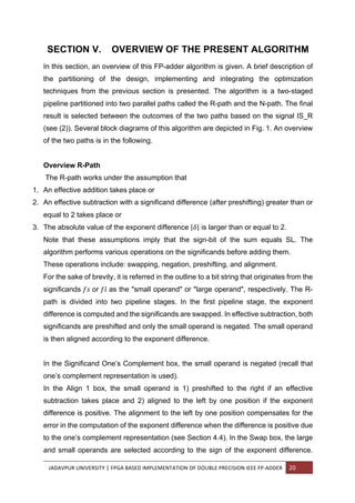
alignment shift by one position takes place if sign med = 1. Table 1 summarizes the
specification of FSOPβ[-1 : 53].
In the Swap region, the large operand is selected based on sign big. The small
operand is selected for the medium exponent difference (based on sign med) interval
and for the large exponent difference interval (based on sign big).
The Preshift 2 region deals with preshifting the minuend in case an effective
subtraction takes place.
Specification: R-path Second Cycle
Table 1 β Value of FSOPβ [-1:53] according to Fig. 1
SIGN_MED S.EFF Pre
shift
(Left)
Align
shift
(Right)
Accumulated
right shift
FSOPβ[-1:53]
0 0 0 1 1 (00,FBO[0:52])
1 1 1 0 (1,FBO[0:52],1)
1 0 0 0 0 (0,FAO[0:52],0)
1 1 0 -1 (FAO[0:52],11)
28. JADAVPUR UNIVERSITY | FPGA BASED IMPLEMENTATION OF DOUBLE PRECISION IEEE FP-ADDER 27
The input to the second cycle consists of: The sign bit SL, a representation of the
exponent el, the significand strings FLP[-1:52] and FSOPA[-1:116], and the rounding
mode.
Together with the sign bit SL, the rounding mode is reduced to one of the three
rounding modes: RZ, RNE or RI (see Section 4.3). The output consists of the sign bit
SL, the exponent string, and the normalized and rounded significand π_πππ β [1,2)
represented by F_FAR[0 : 52]. If the significand sum (after pre-shifting) is greater than
or equal to 1, then the output of the second cycle of the R-path satisfies:
πππ π π’π = πππ( β1 >;
β (πππ + ππ πππ + π. πΈπΉπΉ β 25,,ΕΈ
))
In effective subtraction, 25,,ΕΈ
is added to correct the sum of the oneβs complement
representations to the sum of twoβs complement representations by the lazy increment
from the first clock cycle. Fig. 1 depicts the partitioning of the computations in the 2nd
cycle of the R-path into basic blocks and specifies the input- and output-signals of
each of these basic blocks.
Details: R-Path First Cycle
Fig. 2 depicts a detailed block diagram of the first cycle of the R-path. The
nonstraightforward regions are described below.
The Exponent Difference region is implemented by cascading a 7-bit adder with a 5-
bit adder. The 7-bit adder computes the lazy oneβs complement exponent difference if
the exponent difference is in the medium interval. This difference is converted to a
sign and magnitude representation denoted by π πππ_πππ and πππ_πππ . The
cascading of the adders enables us to evaluate the exponent difference (for the
medium interval) in parallel with determining whether the exponent difference is in the
big range. The SIGN_BIG signal is simply the MSB of the lazy oneβs complement
exponent difference. The IS_BIG signal is computed by OR-ing the bits in positions [6
: 10] of the magnitude of the lazy oneβs complement exponent difference. This explains
why the medium interval is not symmetric around zero.
The Align 1 region depicted in Fig. 2 is an optimization of the Preshift and Align1 region
in Fig. 1. The reader can verify that the implementation of the Align 1 region satisfies
the specification of FSOPβ[-1 : 53] that is summarized in Table 1.
29. JADAVPUR UNIVERSITY | FPGA BASED IMPLEMENTATION OF DOUBLE PRECISION IEEE FP-ADDER 28
The following condition is computed during the computation of the exponent
difference πΌπ_π 1 βΊ ( ππ β ππ ) β₯ 2
βΊ ππ π‘πππ(πΌπ_π΅πΌπΊ , ππ΄πΊ_ππΈπ·[5: 0], π΄ππ·(ππ΄πΊ_ππΈπ·(0), πππ(ππΌπΊπ_π΅πΌπΊ))),
which will be used later for the selection of the valid path. Note that, the exponent
difference is computed using oneβs complement representation. This implies that the
magnitude is off by one when the exponent difference is positive. In particular, the
case of the exponent difference equal to 2 yields a magnitude of 1 and a sign bit of 0.
This is why the expression AND(MAG_MED[0],NOT(SIGN BIG)) appears in the OR-
tree used to compute the IS_R signal.
Details: R-Path Second Cycle
Fig. 2 depicts a detailed block diagram of the second cycle of the R-path. The details
of the implementation are described below. Our implementation of the R-path in the
second cycle consists of two parallel paths called the upper part and the lower part.
The upper part deals with positions [-1:52] of the significands and the lower part deals
with positions [53:116] of the significands. The processing of the lower part has to take
into account two additional values: the rounding injection, which depends only on the
reduced rounding mode, and the missing ULP (2_116) in effective subtraction due to
the oneβs complement representation. The processing of FSOPA[53:116], INJ[53:116]
and S.EFF β 25,,ΕΈ
is based on:
ππ΄πΌπΏ[52: 116] =
πΉππππ΄[53: 116] + πΌππ½[53: 116] ππ π. πΈπΉπΉ = 0
πΉππππ΄[53: 116] + πΌππ½[53: 116] + 25,,ΕΈ
ππ π. πΈπΉπΉ = 1
The bits πΆ[52], π β, πβ are defined by πΆ[52] = ππ΄πΌπΏ[52] , Rβ=TAIL[53],
Sβ=OR(TAIL[54:116]). They are computed by using a 2-bit injection string that has a
different value for effective addition and subtraction.
Effective addition- Let π:β¦β¦ denote the sticky bit that corresponds to FSOPA[54:116],
then π:β¦β¦= OR(FSOPA[54], . . . ,FSOPA[116]). The injection can be restricted to two
bits INJ[53 : 54] and we simply perform a 2-bit addition to obtain the three bits C[52],Rβ,
Sβ:
(πΆ 52 , π β²
, πβ²) = πΌππ½[53: 54] + (πΉππππ΄ 53 , π:β¦β¦) .
30. JADAVPUR UNIVERSITY | FPGA BASED IMPLEMENTATION OF DOUBLE PRECISION IEEE FP-ADDER 29
Effective subtraction- In this case, we still have to add to FSOPA the missing 25,,ΕΈ
that we neglected to add during the first cycle. Let π>kS denote the sticky bit that
corresponds to bit positions [54:116] in the binary representation of
πΉππππ΄[54: 116] + 25,,ΕΈ
, then π>kS = ππ (πππ(πΉππππ΄[54: 116])),
The addition of 25,,ΕΈ
can create a carry to position [53], which we denote by C[53].
The value of C[53] is one if FSOPA[54:116] is all ones, in which case the addition of
25,,ΕΈ
creates a carry that ripples to position [53]. Therefore, C[53]=NOT(π>kS). Again,
the injection can be restricted to two bits INJ[53:54], and we compute C[52],Rβ, Sβ by
(πΆ 52 , π β²
, πβ²) = πΌππ½[53: 54] + (πΉππππ΄ 53 , π:β¦β¦) + 2πΆ[53]
The result of this addition cannot be greater than 7 β 25zβ
, because C[53]= NOT(π >kS).
A fast implementation of the computation of C[52], Rβ, Sβ proceeds as follows. Let S
=π:β¦β¦ in effective addition, and S= π>kS in effective subtraction. Based on S.EFF,
FSOPA[53] and INJ[53:54], the signals C[52], Rβ, Sβ are computed in two paths: one
assuming that S = 1 and the other assuming that S = 0.
Fig. 2 depicts a naive method of computing the sticky bit S to keep the presentation
structured rather than obscure it with optimizations. A conditional inversion of the bits
of FSOPA[54 : 116] is performed by XOR-ing the bits with S.EFF. The possibly
inverted bits are then input to an OR-tree. This suggestion is somewhat slow and
costly. A better method would be to compute the OR and AND of (most of) the bits of
FS[54 : 116] during the alignment shift in the first cycle. The advantages of advancing
(most of) the sticky bit computation to the first cycle is twofold:
1) There is ample time during the alignment shift whereas the sticky bit should be ready
after at most 5 logic levels in the second cycle; and
2) This saves the need to latch all 63 bits (corresponding to FS[54 : 116]) between the
two pipeline stages. The upper part computes the correctly rounded sum (including
post-normalization) and uses for the computation of the strings FLP[-1:52],FSOPA[-
1:52], and (C[52],Rβ, Sβ).
The rest of the algorithm is identical to the rounding presented, analyzed, and proven
in [8] for FP multiplication.
31. JADAVPUR UNIVERSITY | FPGA BASED IMPLEMENTATION OF DOUBLE PRECISION IEEE FP-ADDER 30
SECTION VII. DELAY ANALYSIS REPORTING
In this section, the delay of this FP-adder algorithm has been reported. The original
analysis was made by using the Logical Effort Model [33]. In the analysis of gate
delays, this delay model allows a rigorous treatment of the contributions of fanouts
and gate sizing independent of the used technology, process, voltage, or feature size.
Based on this delay model, a proposal of the delay-optimal implementation of this FP
addition algorithm was made by the authors, by considering optimized gate sizing and
driver insertion. For comparisons the delay estimations are scaled from this model to
units of FO4 inverter delays (inverter delay with a fanout of four). The use of this unit
has been a popular choice in literature on circuit design whenever delays are to be
determined in technology-independent terms. It has been demonstrated for several
examples that delay estimations in FO4 delay units are rather insensitive to choices
of technological parameters [12]. The description of, how the delay analysis, provided
by the authors, differ from the traditional one, has been described in [28], [29]. In the
more recent analysis, each gate is assigned an independent size and delay. This
allows for precise modeling of fanout contributions and full custom gate size
optimizations for minimum delay. The previously estimated the total delay of this
algorithm was 24 logic levels between latches, which could be evenly partitioned into
two stages with 12 logic levels each. One logic level (XOR delay with a fanout of 1)
has a delay of 1.6 FO4 inverter delay units in the current framework (this is because
d(XOR1) = 8 logical effort delays and d(FO4) = 5 logical effort delays), so that the
previous analysis estimated the delay of this algorithm to be 38:4 FO4 delays. This is
approximately 19 FO4 delays for each of two pipeline stages between latches.
32. JADAVPUR UNIVERSITY | FPGA BASED IMPLEMENTATION OF DOUBLE PRECISION IEEE FP-ADDER 31
SECTION VIII. IMPLEMENTATION
This algorithm has been implemented using the Xilinx ISE v.9.2i with a XC2V6000
device of virtex2 family, package FF1152. The top level source is Hardware
Description Language type, with a XST(VHDL/VERILOG) environment. The basic
block level implementation is done with VHDL following the connections as per the
algorithm. Instead of a compound adder as it was in the algorithm a simpler model of
addition circuitry has been used in the implementation level. A further study is
necessary for the scope of using the aforementioned adder circuit along with the
implementation of the βN-pathβ mentioned in the algorithm.
The detailed block diagram of the block level implementation is given inFig.1 and Fig.2.
The system requirement for the above mentioned environment is given below.
The synthesis report of the generated circuit model is presented here.
The general debugging tool used for the implementation process is the ISE editor and
Modelsim v.6.3.
The implementation process is shown hierarchically:
Algorithm undestanding
Developing building blocks
(in VHDL)
Simulation of the abstact
model Debugging
Pipelining and optimizing
Chip implementation
(RC10)
33. JADAVPUR UNIVERSITY | FPGA BASED IMPLEMENTATION OF DOUBLE PRECISION IEEE FP-ADDER 32
System Information
Machine name: ADRIN-E68E783C5
Operating System: Windows XP Professional (5.1, Build 2600) Service Pack 2
(2600.xpsp_sp2_rtm.040803-2158)
Language: English (Regional Setting: English)
System Manufacturer: Hewlett-Packard
System Model: HP xw4300 Workstation
BIOS: Default System BIOS
Processor: Intel(R) Pentium(R) 4 CPU 3.80GHz (2 CPUs)
Memory: 1536MB RAM
Page File: 485MB used, 2945MB available
Windows Dir: C:WINDOWS
DirectX Version: DirectX 9.0c (4.09.0000.0904)
DX Setup Parameters: Not found
DxDiag Version: 5.03.2600.2180 32bit Unicode
34. JADAVPUR UNIVERSITY | FPGA BASED IMPLEMENTATION OF DOUBLE PRECISION IEEE FP-ADDER 33
SYNTHESIS REPORT:
Synthesis Options Summary
Source Parameters ----
Input File Name : "top_module.prj"
Input Format : mixed
Ignore Synthesis Constraint File : NO
Target Parameters ----
Output File Name : "top_module"
Output Format : NGC
Target Device : xc2v6000-4-ff1152
Source Options ----
Top Module Name : top_module
Automatic FSM Extraction : YES
FSM Encoding Algorithm : Auto
Safe Implementation : No
FSM Style : lut
RAM Extraction : Yes
RAM Style : Auto
ROM Extraction : Yes
Mux Style : Auto
Decoder Extraction : YES
Priority Encoder Extraction : YES
Shift Register Extraction : YES
Logical Shifter Extraction : YES
XOR Collapsing : YES
ROM Style : Auto
Mux Extraction : YES
Resource Sharing : YES
Asynchronous To Synchronous : NO
Multiplier Style : auto
Automatic Register Balancing : No
Target Options ----
Add IO Buffers : YES
Global Maximum Fanout : 500
Add Generic Clock Buffer(BUFG) : 16
Register Duplication : YES
Slice Packing : YES
Optimize Instantiated Primitives : NO
Convert Tristates To Logic : Yes
35. JADAVPUR UNIVERSITY | FPGA BASED IMPLEMENTATION OF DOUBLE PRECISION IEEE FP-ADDER 34
Use Clock Enable : Yes
Use Synchronous Set : Yes
Use Synchronous Reset : Yes
Pack IO Registers into IOBs : auto
Equivalent register Removal : YES
General Options ----
Optimization Goal : Speed
Optimization Effort : 1
Library Search Order : top_module.lso
Keep Hierarchy : NO
RTL Output : Yes
Global Optimization : AllClockNets
Read Cores : YES
Write Timing Constraints : NO
Cross Clock Analysis : NO
Hierarchy Separator : /
Bus Delimiter : <>
Case Specifier : maintain
Slice Utilization Ratio : 100
BRAM Utilization Ratio : 100
Verilog 2001 : YES
Auto BRAM Packing : NO
Slice Utilization Ratio Delta : 5
HDL Synthesis Report
Macro Statistics
# Adders/Subtractors : 5
11-bit adder : 1
5-bit adder carry in : 1
53-bit adder : 2
8-bit adder : 1
# Registers : 12
1-bit register : 5
11-bit register : 3
118-bit register : 1
52-bit register : 2
54-bit register : 1
# Latches : 1
118-bit latch : 1
# Multiplexers : 1
11-bit 4-to-1 multiplexer : 1
# Logic shifters : 1
118-bit shifter logical right : 1
# Xors : 16
1-bit xor2 : 15
1-bit xor3 : 1
37. JADAVPUR UNIVERSITY | FPGA BASED IMPLEMENTATION OF DOUBLE PRECISION IEEE FP-ADDER 36
Selected Device : 2v6000ff1152-4
Number of Slices: 528 out of 33792 1%
Number of Slice Flip Flops: 308 out of 67584 0%
Number of 4 input LUTs: 932 out of 67584 1%
Number of IOs: 195
Number of bonded IOBs: 195 out of 824 23%
Number of GCLKs: 2 out of 16 12%
TIMING REPORT
NOTE: THESE TIMING NUMBERS ARE ONLY A SYNTHESIS ESTIMATE.
FOR ACCURATE TIMING INFORMATION PLEASE REFER TO THE TRACE
REPORT GENERATED AFTER PLACE-and-ROUTE.
Clock Information:
-----------------------------------------------+-----------------------------------------+-------+
Clock Signal | Clock buffer(FF name) | Load |
-----------------------------------------------+-----------------------------------------+-------+
Clock | BUFGP | 251 |
-----------------------------------------------+-----------------------------------------+--------|
seff1 (Inst_compliment5353/ | | |
Mxor_s_temp_xo<1>1:O) | BUFG(*)(Inst_allignment/ | |
|goout_101) | 57 |
-----------------------------------------------+-----------------------------------------+--------+
Asynchronous Control Signals Information:
-----------------------------------+-----------------------------+--------+
Control Signal | Buffer(FF name) | Load |
-----------------------------------+------------------------------+-------+
Preset | IBUF | 240 |
-----------------------------------+------------------------------+-------+
Timing Summary:
Speed Grade: -4
Minimum period: 10.631ns (Maximum Frequency: 94.061MHz)
Minimum input arrival time before clock: 1.712ns
Maximum output required time after clock: 16.396ns
Maximum combinational path delay: No path found
Timing Detail:
All values displayed in nanoseconds (ns)
Timing constraint: Default period analysis for Clock 'clock'
39. JADAVPUR UNIVERSITY | FPGA BASED IMPLEMENTATION OF DOUBLE PRECISION IEEE FP-ADDER 38
PLACE AND ROUTE REPORT:
Release 9.2i par J.36
Copyright (c) 1995-2007 Xilinx, Inc. All rights reserved.
ADRIN-E68E783C5:: Wed Oct 05 14:42:59 2011
Device speed data version: "PRODUCTION 1.121 2007-04-13".
Device Utilization Summary:
Number of BUFGMUXs 2 out of 16 12%
Number of External IOBs 195 out of 824 23%
Number of LOCed IOBs 0 out of 195 0%
Number of SLICEs 546 out of 33792 1%
Overall effort level (-ol): Standard
Placer effort level (-pl): High
Placer cost table entry (-t): 1
Router effort level (-rl): Standard
REAL time consumed by placer: 20 secs
CPU time consumed by placer: 19 secs
Writing design to file top_module.ncd
Total REAL time to Placer completion: 21 secs
Total CPU time to Placer completion: 20 secs
Total REAL time to Router completion: 40 secs
Total CPU time to Router completion: 39 secs
Generating Clock Report:
+---------------------+------------------+----------+---------+------------------+--------------------+
| Clock Net | Resource |Locked |Fanout |Net Skew(ns) |Max Delay(ns) |
+---------------------+------------------+----------+---------+------------------+--------------------+
| clock_BUFGP | BUFGMUX3P| No | 197 | 0.353 | 2.396 |
+---------------------+------------------+----------+---------+------------------+---------------------+
| Seff |BUFGMUX4P| No | 53 | 0.095 | 2.134 |
+---------------------+------------------+----------+---------+------------------+---------------------+
* Net Skew is the difference between the minimum and maximum routing
only delays for the net. Note this is different from Clock Skew which
is reported in TRCE timing report. Clock Skew is the difference between
the minimum and maximum path delays which includes logic delays.
40. JADAVPUR UNIVERSITY | FPGA BASED IMPLEMENTATION OF DOUBLE PRECISION IEEE FP-ADDER 39
The Delay Summary Report
The NUMBER OF SIGNALS NOT COMPLETELY ROUTED for this design is: 0
The AVERAGE CONNECTION DELAY for this design is: 2.675
The MAXIMUM PIN DELAY IS: 14.081
The AVERAGE CONNECTION DELAY on the 10 WORST NETS is: 9.965
Listing Pin Delays by value: (nsec)
d < 3.00 < d < 6.00 < d < 9.00 < d < 12.00 < d < 15.00 d >= 15.00
--------- --------- --------- --------- --------- ---------
2723 702 391 79 36 0
Summary report for the RC10 chip implementation:
Clock: 110 MHz
ISE Project Status
Project File: FPadder.ise Current State: Programming File Generated
Module Name: top_module
β’ Errors:
No Errors
Target Device: xc3s1500l-4fg320
β’ Warnings:
20 Warnings
Product Version: ISE 9.2i
β’ Updated:
Tue Jun 26 16:00:21 2012
ISE Partition Summary
No partition information was found.
41. JADAVPUR UNIVERSITY | FPGA BASED IMPLEMENTATION OF DOUBLE PRECISION IEEE FP-ADDER 40
Device Utilization Summary
Logic Utilization Used Available Utilization Note(s)
Number of Slice Flip Flops 421 26,624 1%
Number of 4 input LUTs 492 26,624 1%
Logic Distribution
Number of occupied Slices 491 13,312 3%
Number of Slices containing only related logic 491 491 100%
Number of Slices containing unrelated logic 0 491 0%
Total Number of 4 input LUTs 668 26,624 2%
Number used as logic 492
Number used as a route-thru 139
Number used for Dual Port RAMs 36
Number used as Shift registers 1
Number of bonded IOBs 39 221 17%
IOB Flip Flops 15
Number of Block RAMs 1 32 3%
Number of GCLKs 4 8 50%
Number of DCMs 2 4 50%
Total equivalent gate count for design 89,436
Additional JTAG gate count for IOBs 1,872
Performance Summary
Final Timing Score: 0 Pinout Data: Pinout Report
Routing Results: All Signals Completely Routed Clock Data: Clock Report
Timing Constraints: All Constraints Met
Detailed Reports
Report Name Status Generated Errors Warnings Infos
Synthesis Report
Translation Report Current Tue Jun 26 15:59:03 2012 0 0 0
Map Report Current Tue Jun 26 15:59:15 2012 0 3 Warnings 4 Infos
Place and Route Report Current Tue Jun 26 15:59:52 2012 0 9 Warnings 1 Info
Static Timing Report Current Tue Jun 26 16:00:00 2012 0 8 Warnings 2 Infos
Bitgen Report Current Tue Jun 26 16:00:19 2012 0 0 1 Info
49. JADAVPUR UNIVERSITY | FPGA BASED IMPLEMENTATION OF DOUBLE PRECISION IEEE FP-ADDER 48
SECTION VIII. FUTURE SCOPE
The IEEE double precision FP adder circuit finds usefulness in numerous occasions.
Therefore this present implementation can be stretched to cover up the whole
algorithmic process and it has a greater affinity for the optimization of the total process,
including the rounding mechanisms and the addition process. Also the computation of
the carry and sticky bit requires a lot of logical efforts which are can be minimized.
Upon optimization this can be used in various floating point operation incorporating
with different FPGAs.
50. JADAVPUR UNIVERSITY | FPGA BASED IMPLEMENTATION OF DOUBLE PRECISION IEEE FP-ADDER 49
BIBLIOGRAPHY
[1] S. Bar-Or, G. Even, and Y. Levin, βGeneration of Representative Input Vectors for
Parametric Designs: from Low Precision to High Precision,β Integration, the VLSI J.,
vol. 36, issues 1-2, pp. 69-82, Sept. 2003.
[2] A. Beaumont-Smith, N. Burgess, S. Lefrere, and C. Lim, βReduced Latency IEEE
Floating-Point Standard Adder Architectures,β Proc.14th IEEE Symp. Computer
Arithmetic, pp. 35-43, 1999.
[3] R. Brent and H. Kung, βA Regular Layout for Parallel Adders,β IEEE Trans. On
computers, vol. 31, no. 3, pp. 260-264, Mar. 1982.
[4] J. Bruguera and T. Lang, βUsing the Reverse-Carry Approach for Double-Datapath
Floating-Point Addition,β Proc. 15th IEEE Intβl Symp. Computer Arithmetic (Arith15),
pp. 203-210, June 2001.
[5] M. Daumas and D. Matula, βRecoders for Partial Compression and Rounding,β
Technical Report RR97-01, Ecole Normale Superieur de Lyon, LIP 1996.
[6] L. Eisen, T. Elliott, R. Golla, and C. Olson, βMethod and System for Performing a
High Speed Floating Point Add Operation.β IBM Corporation, US patent 5790445,
1998.
[7] G. Even, S. MuΒ¨ ller, and P. Seidel, βDual Precision IEEE Floating- Point Multiplier,β
INTEGRATION The VLSI J., vol. 29, no. 2, pp. 167-180, Sept. 2000.
[8] G. Even and P.-M. Seidel, βA Comparison of Three Rounding Algorithms for IEEE
Floating-Point Multiplication,β IEEE Trans Computers, vol. 49, no. 7, pp. 638-650, July
2000.
[9] P. Farmwald, βOn the Design of High Performance Digital Arithmetic Units,β PhD
thesis, Stanford Univ., Aug. 1981
[10] P. Farmwald, βBifurcated Method and Apparatus for Floating-Point Addition with
Decreased Latency Time,β US patent 4639887,1987.
[11] V. Gorshtein, A. Grushin, and S. Shevtsov, βFloating Point Addition Methods and
Apparatus.β Sun Microsystems, US patent 5808926, 1998.
[12]M.Horowitz,βVLSI Scaling for Architects,β http://velox.stanford.
du/papers/VLSIScaling.pdf, 2000.
[13] βIEEE Standard for Binary Floating Point Arithmetic, βANSI/ IEEE754-1985, 1985.
[14] T. Ishikawa, βMethod for Adding/Subtracting Floating-Point Representation Data
and Apparatus for the Same,β Toshiba, K.K., US patent 5063530, 1991.
51. JADAVPUR UNIVERSITY | FPGA BASED IMPLEMENTATION OF DOUBLE PRECISION IEEE FP-ADDER 50
[15] T. Kawaguchi, βFloating Point Addition and Subtraction Arithmetic Circuit
Performing Preprocessing of Addition or Subtraction Operation Rapidly,β NEC, US
patent 5931896, 1999.
[16] Y. Levin, βSupporting Demoralized Numbers in an IEEE Compliant Floating Point
Adder Optimized for Speed,β http:// hyde.eng.tau.ac.il/Projects/FPADD/index.html,
2001.
[17] A. Naini, A. Dhablania, W. James, and D. Das Sarma, β1-GHz HAL SPARC64
Dual Floating Point Unit with RAS Features,β Proc. 15th IEEE Intβl Symp. Computer
Arithmetic (Arith15), pp. 173- 183, June 2001.
[18] T. Nakayama, βHardware Arrangement for Floating-Point Addition and
Subtraction,β NEC, US patent 5197023, 1993.
[19] K. Ng, βFloating-Point ALU with Parallel Paths,β US patent 5136536, Weitek Corp.,
1992.
[20] A. Nielsen, D. Matula, C.-N. Lyu, and G. Even, βIEEE Compliant Floating-Point
Adder that Conforms with the Pipelined Packet- Forwarding Paradigm,β IEEE Trans.
Computers, vol. 49, no. 1,pp. 33-47, Jan. 2000.
[21] S. Oberman, βFloating-Point Arithmetic Unit Including an Efficient Close Data
Path,β AMD, US patent 6094668, 2000.
[22] S. Oberman, H. Al-Twaijry, and M. Flynn, βThe SNAP Project: Design of Floating
Point Arithmetic Units,β Proc. 13th IEEE Symp.Computer Arithmetic, pp. 156-165,
1997.
[23] W.-C. Park, T.-D. Han, S.-D. Kim, and S.-B. Yang, βFloating Point
Adder/Subtractor Performing IEEE Rounding and Addition/Subtraction in Parallel,β
IEICE Trans. Information and Systems, vol. 4, pp. 297-305, 1996.
[24] N. Quach and M. Flynn, βDesign and Implementation of the SNAP Floating-Point
Adder,β Technical Report CSL-TR-91-501,Stanford Univ., Dec. 1991.
[25] N. Quach, N. Takagi, and M. Flynn, βOn fast IEEE Rounding,β Technical Report
CSL-TR-91-459, Stanford Univ., Jan. 1991.
[26] M. Schmookler and K. Nowka, βLeading Zero Anticipation and DetectionβA
Comparison of Methods, Proc. 15th IEEE Symp.Computer Arithmetic, pp. 7-12, 2001.
[27] P.-M. Seidel, βOn The Design of IEEE Compliant Floating-Point Units and Their
Quantitative Analysis,β PhD thesis, Univ. of Saarland, Germany, Dec. 1999.
[28] P.-M. Seidel and G. Even, βHow Many Logic Levels Does Floating-Point Addition
Require?β Proc. 1998 Intβl Conf. Computer Design (ICCD β98): VLSI, in Computers &
Processors, pp. 142-149, Oct. 1998.
52. JADAVPUR UNIVERSITY | FPGA BASED IMPLEMENTATION OF DOUBLE PRECISION IEEE FP-ADDER 51
[29] P.-M. Seidel and G. Even, βOn the Design of Fast IEEE Floating- Point Adders,β
Proc. 15th IEEE Intβl Symp. Computer Arithmetic (Arith15), pp. 184-194, June 2001.
[30] P.-M. Seidel and G. Even, βDelay-Optimized Implementation of IEEE Floating-
Point Addition,β http://www.engr.smu.edu/ seidel/research/fpadd/, 2002.
[31] H. Sit, D. Galbi, and A. Chan, βCircuit for Adding/Subtracting Two Floating-Point
Operands,β Intel, US patent 5027308, 1991.
[32] D. Stiles, βMethod and Apparatus for Performing Floating-Point Addition,β AMD,
US patent 5764556, 1998.
[33] I. Sutherland, B. Sproull, and D. Harris, Logical Effort: Designing Fast CMOS
Circuits. Morgan Kaufmann 1999.
[34] A. Tyagi, βA Reduced-Area Scheme for Carry-Select Adders,β IEEE Trans.
Computers, vol. 42, no. 10, Oct. 1993.
[35] H. Yamada, F. Murabayashi, T. Yamauchi, T. Hotta, H. Sawamoto, T. Nishiyama,
Y. Kiyoshige, and N. Ido, βFloating-Point Addition/ Subtraction Processing Apparatus
and Method Thereof,β Hitachi, US patent 5684729, 1997.
[36] Stefan Sjoholm, Lennart Lindh βVHDL for designersβ Prentice Hall Europe, ISBN
0-13-473414-9.
[37] Kavin Skahill βVHDL for PROGRAMMABLE LOGICβ
[38] ACTEL βHDL CODING style guideβ.