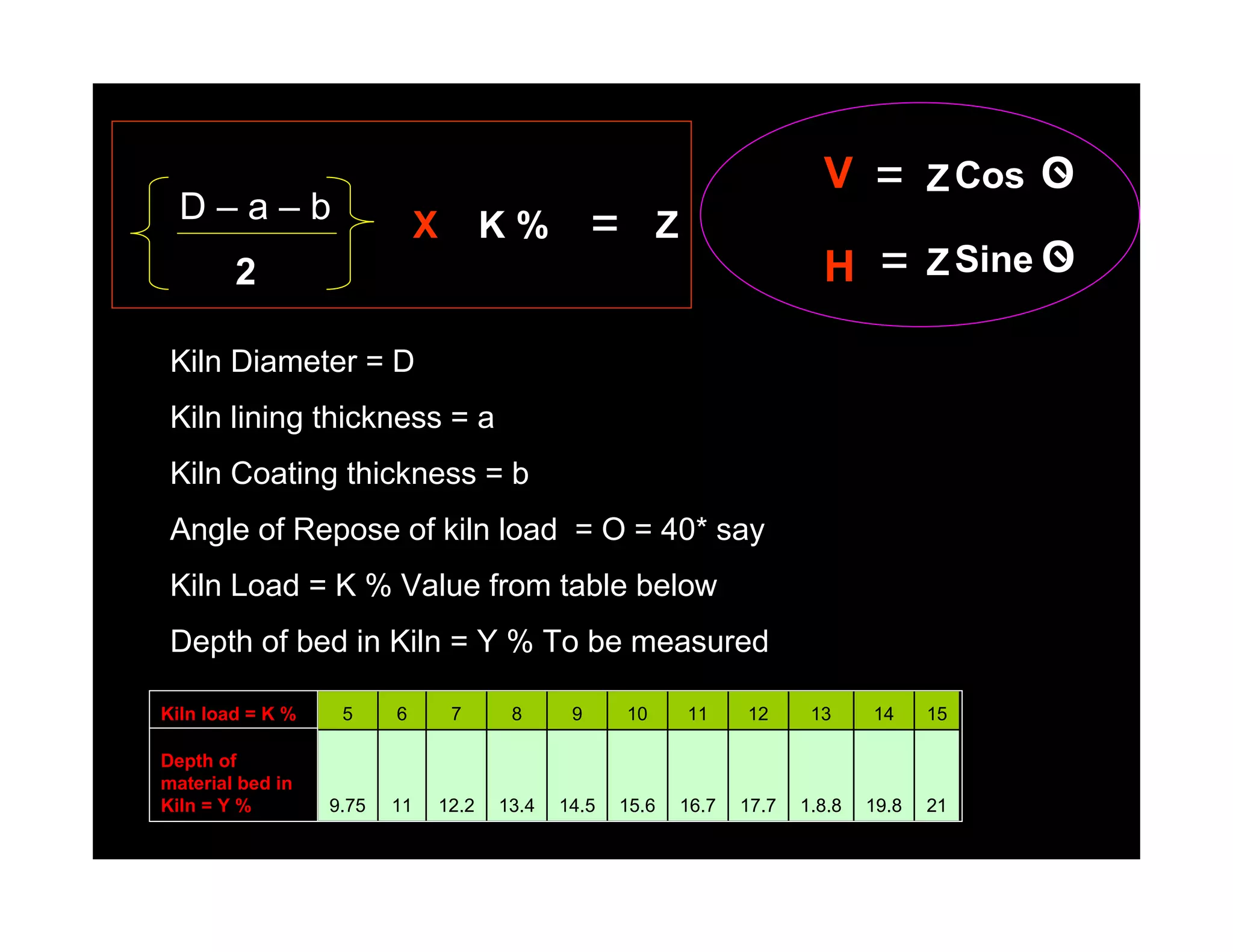
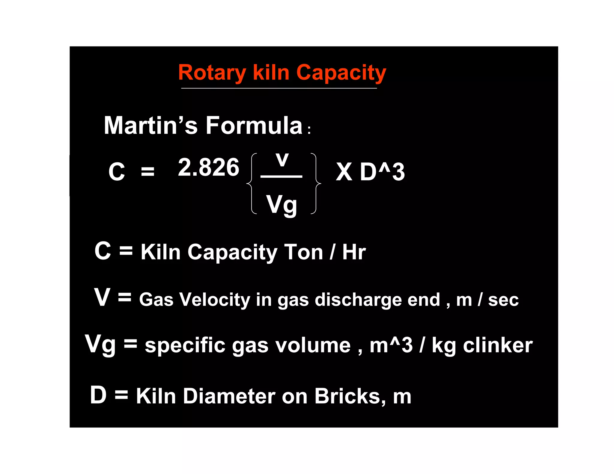
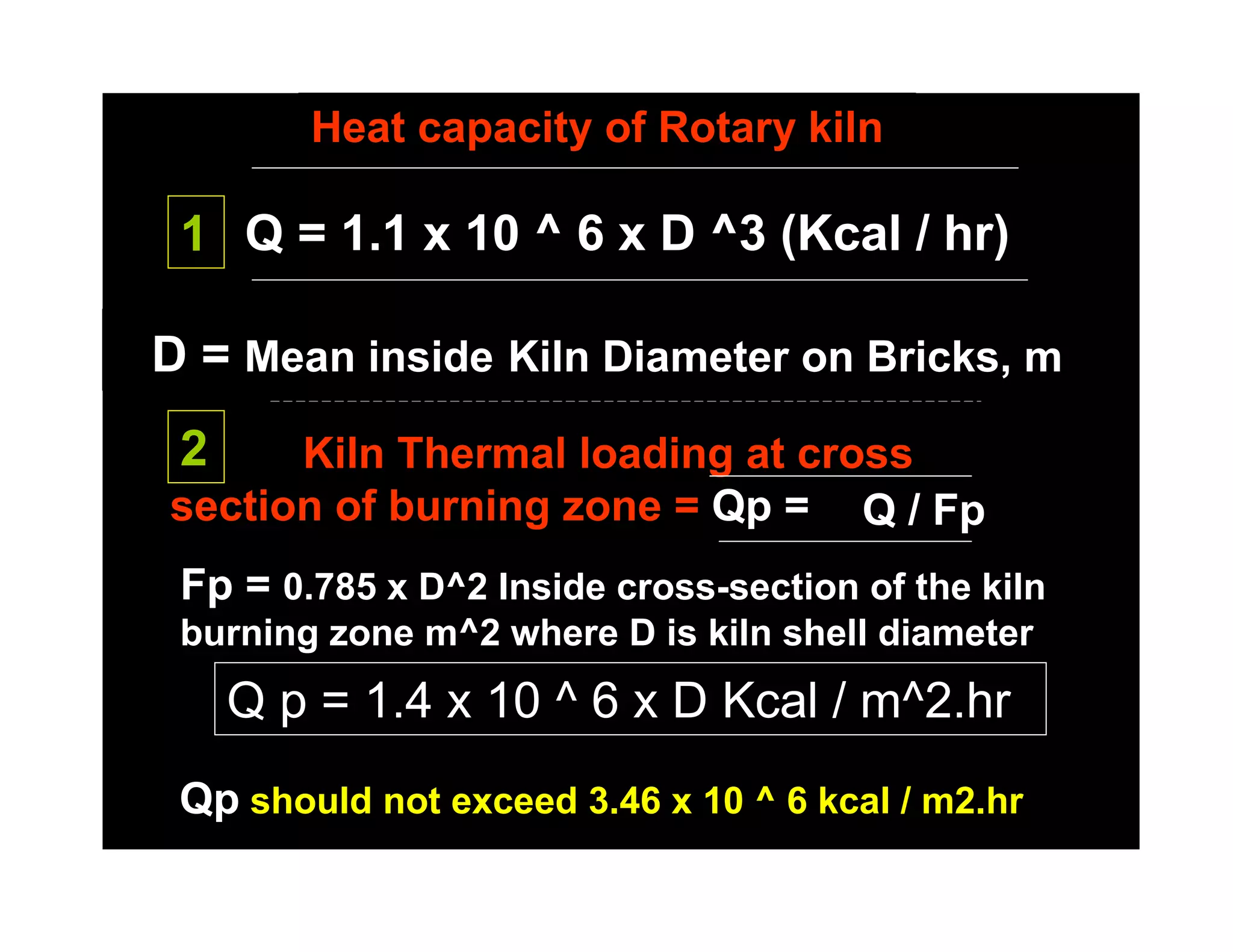
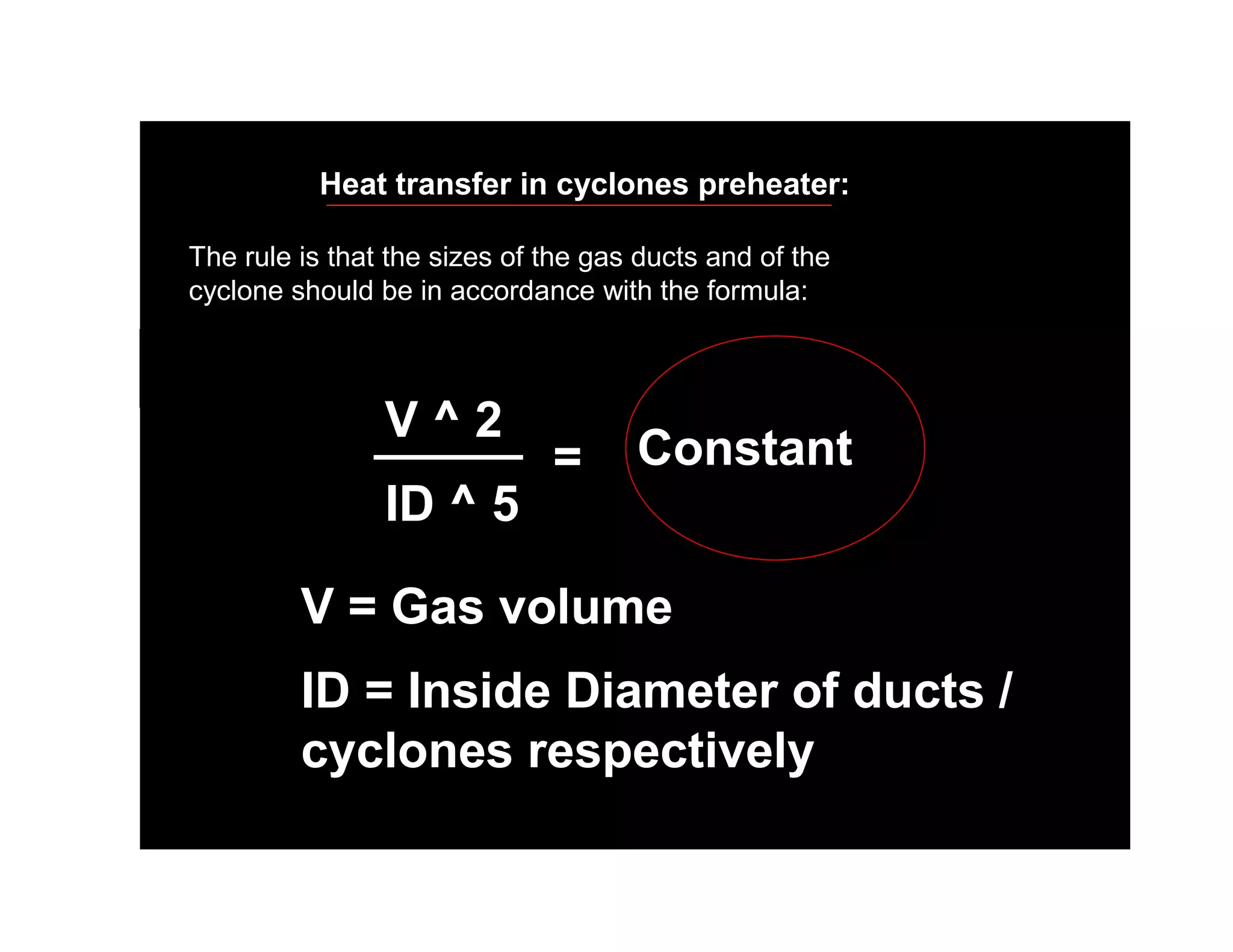
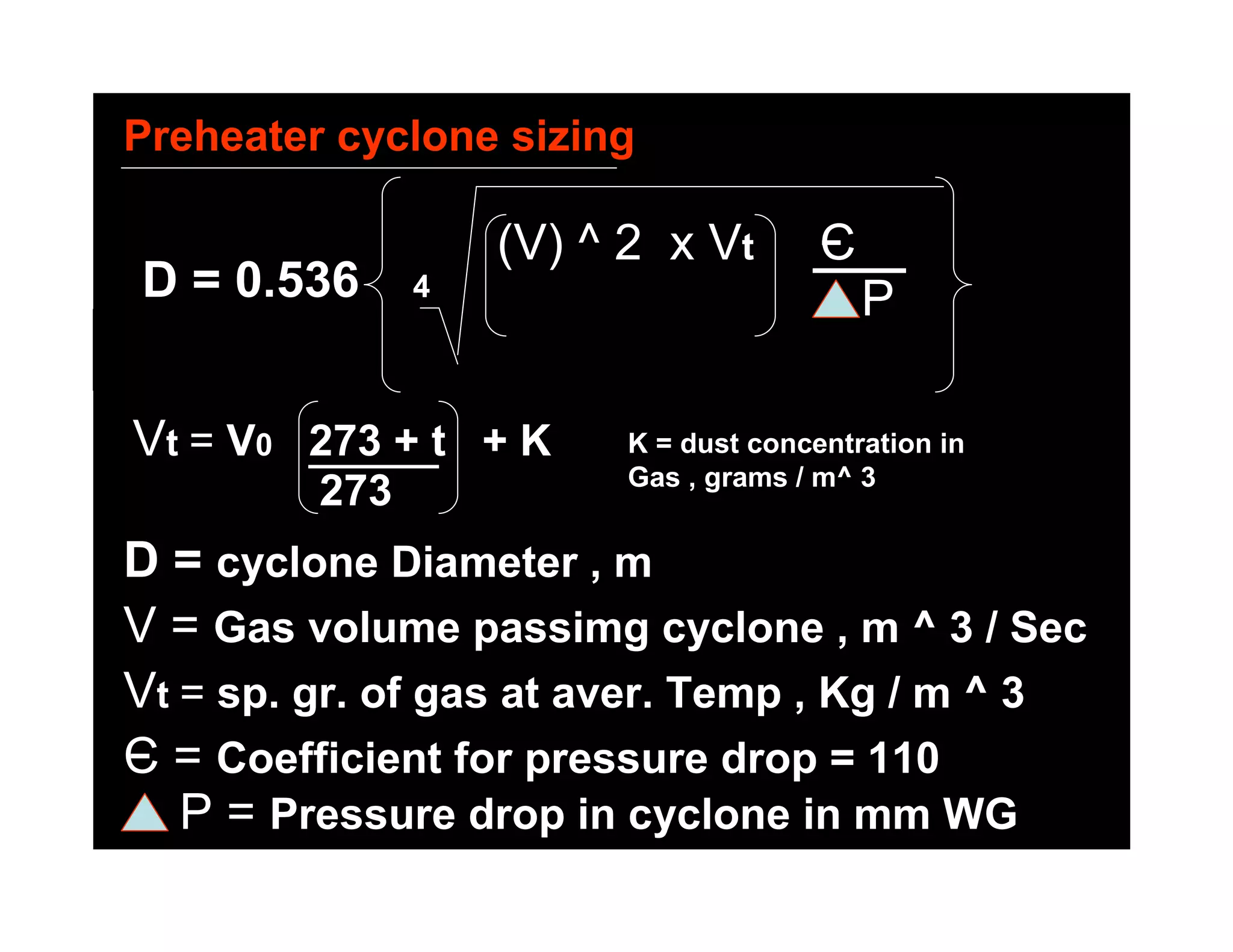
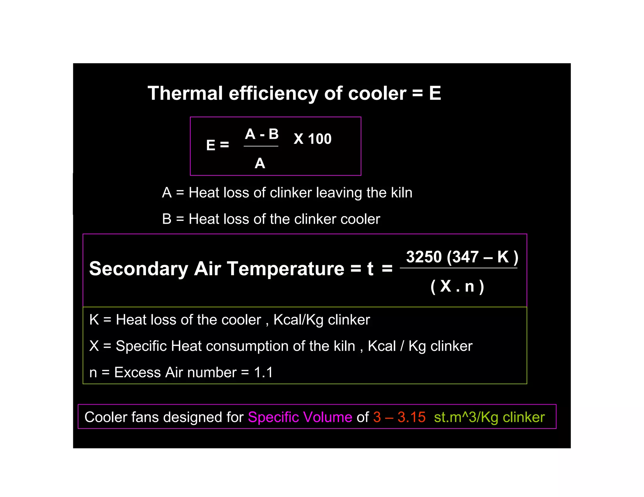
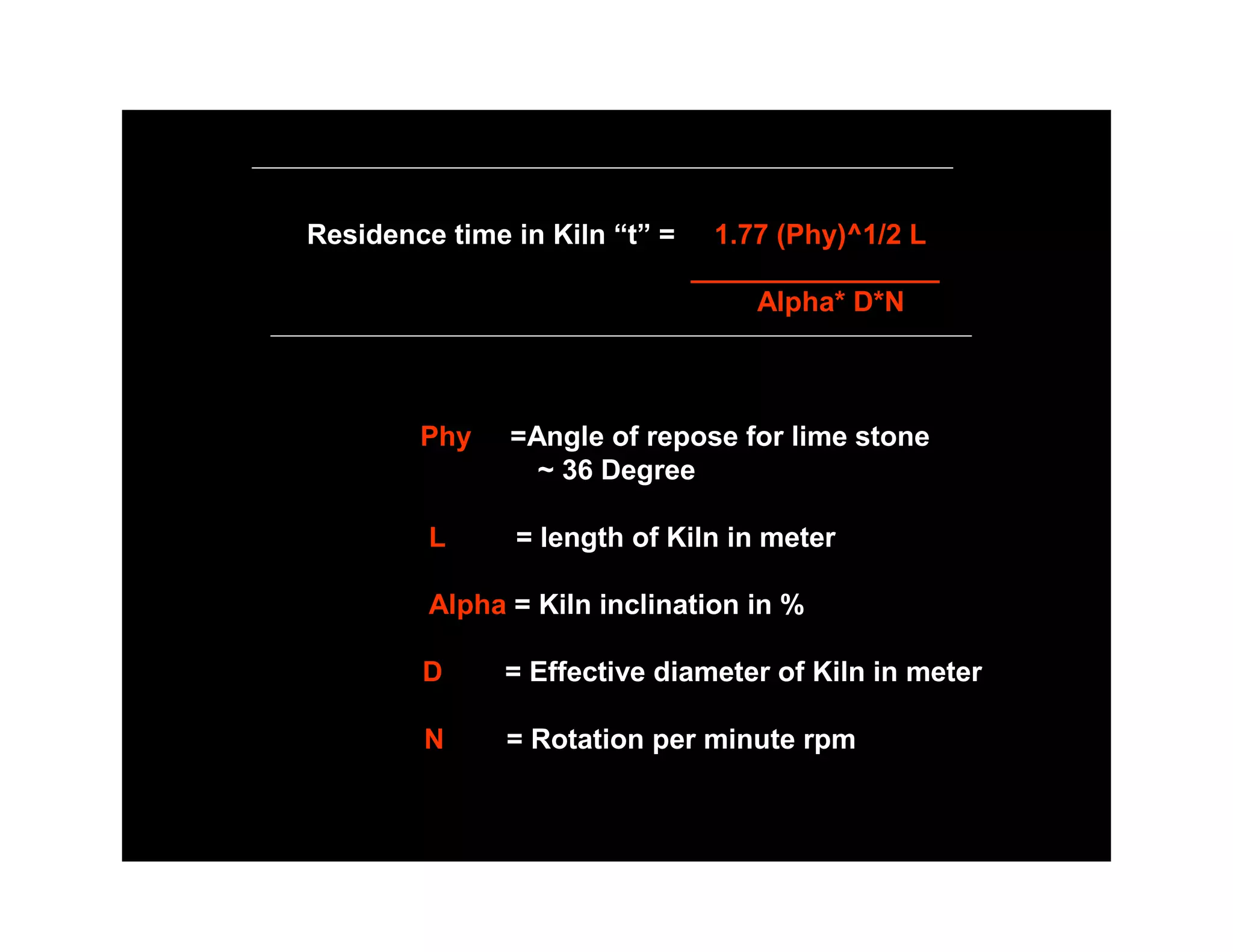
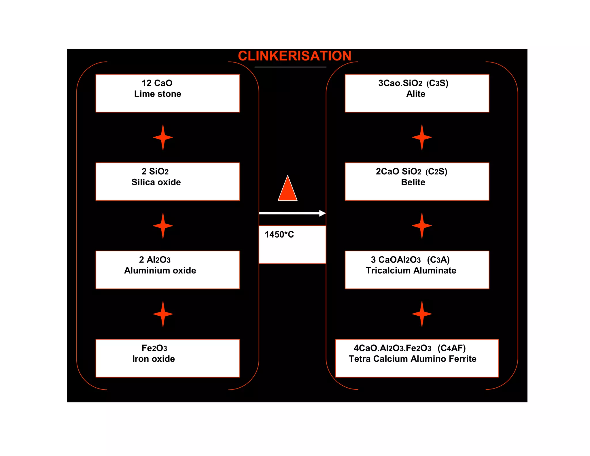
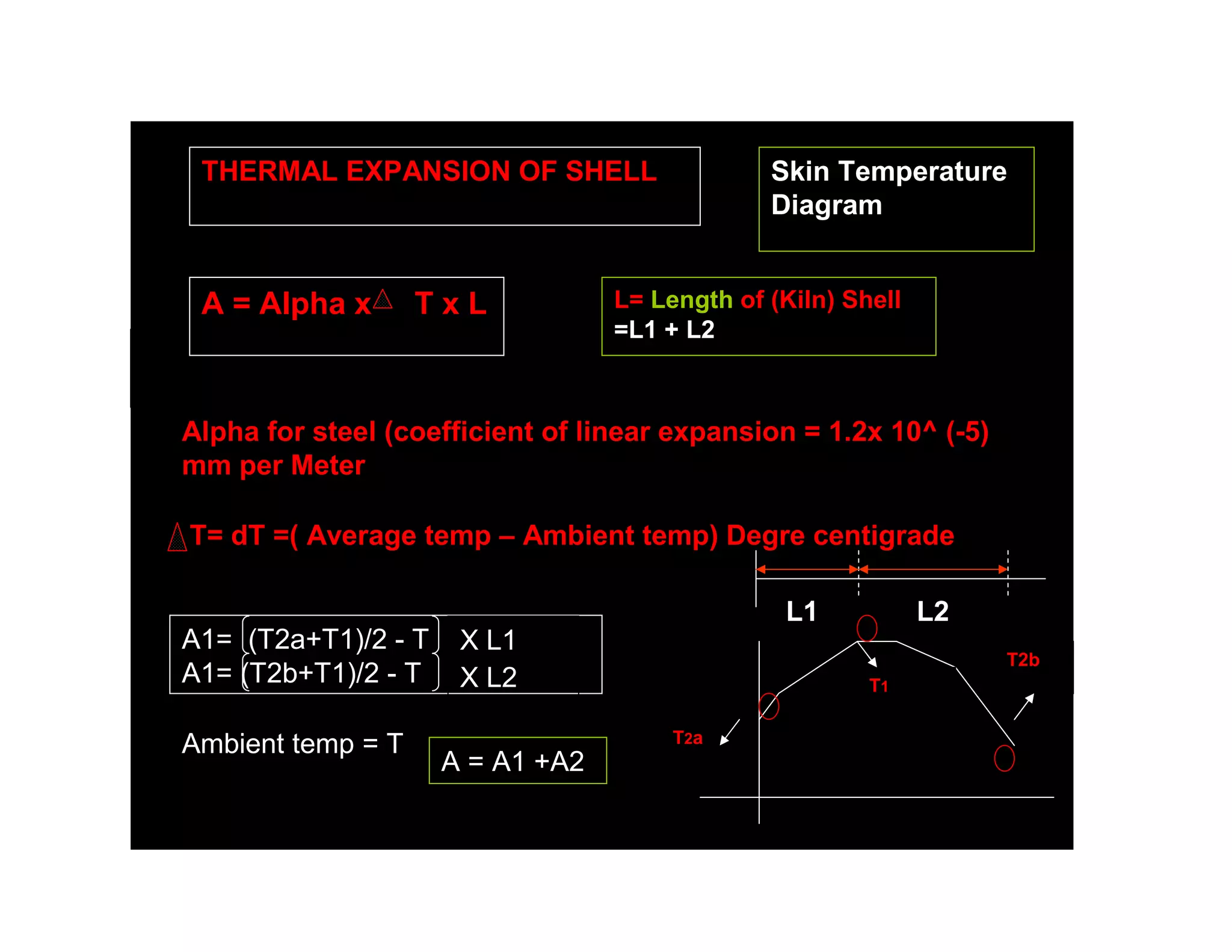
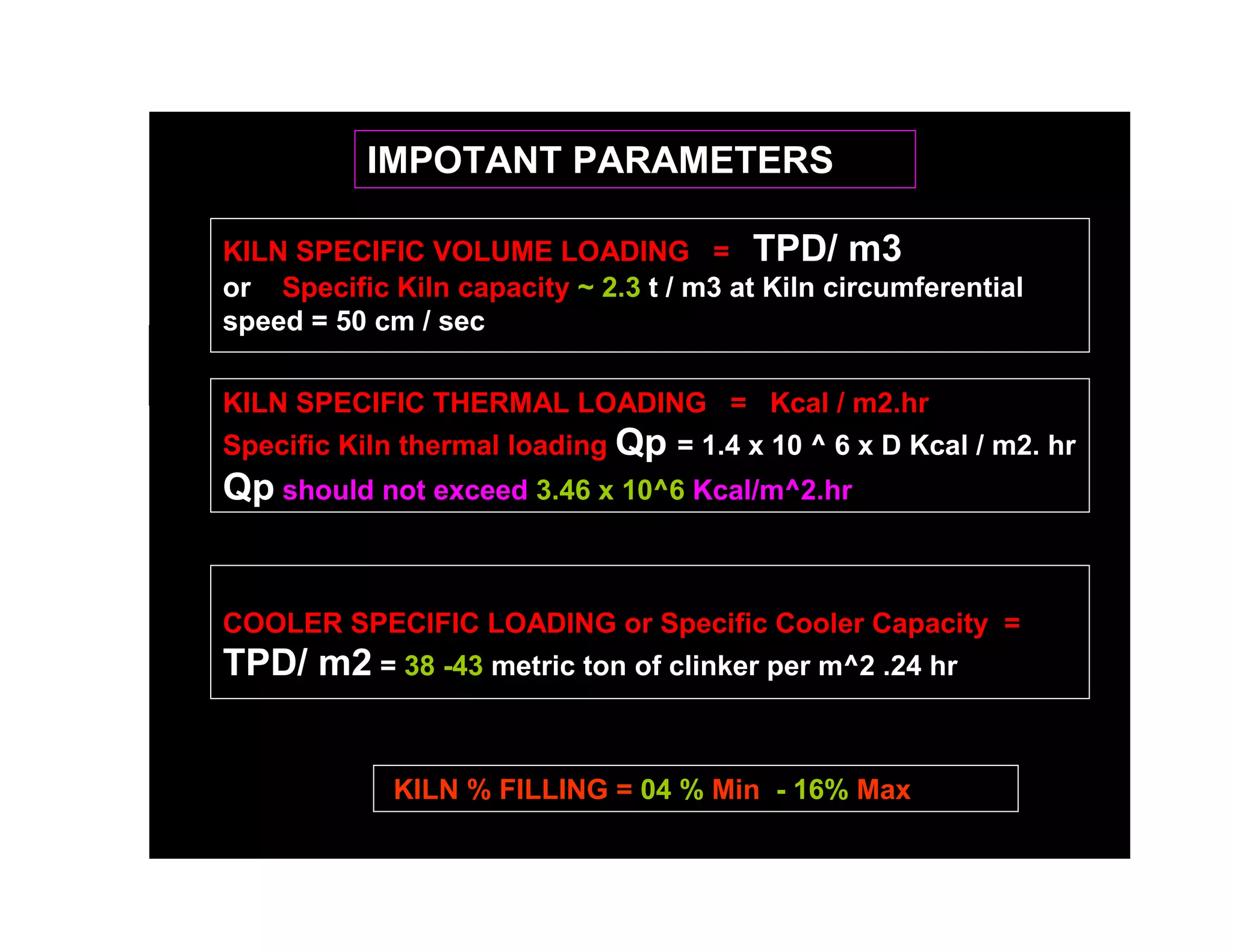
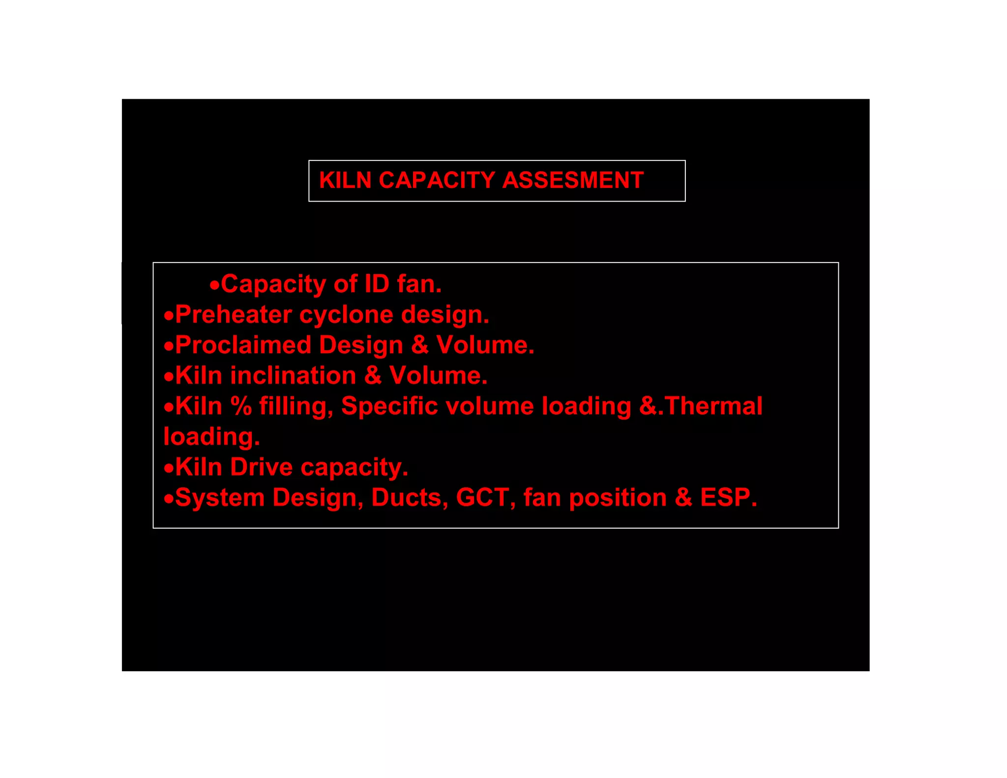
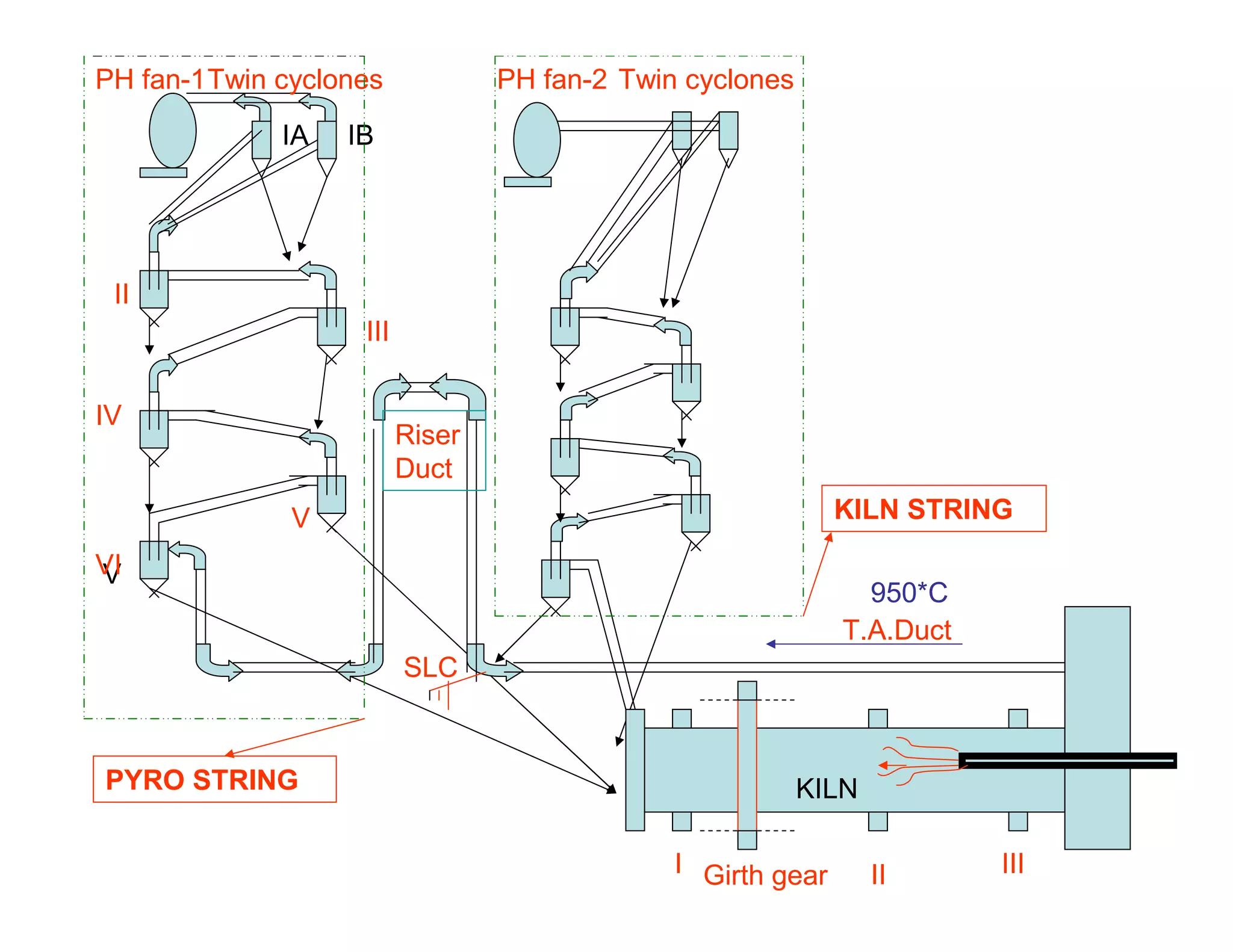
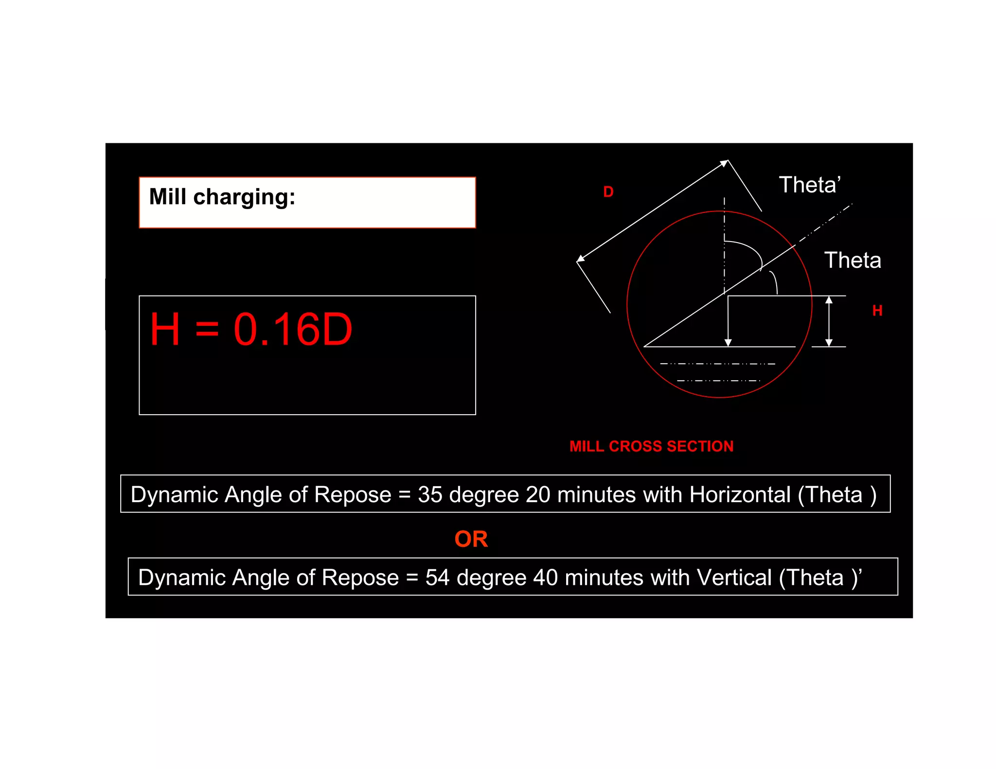
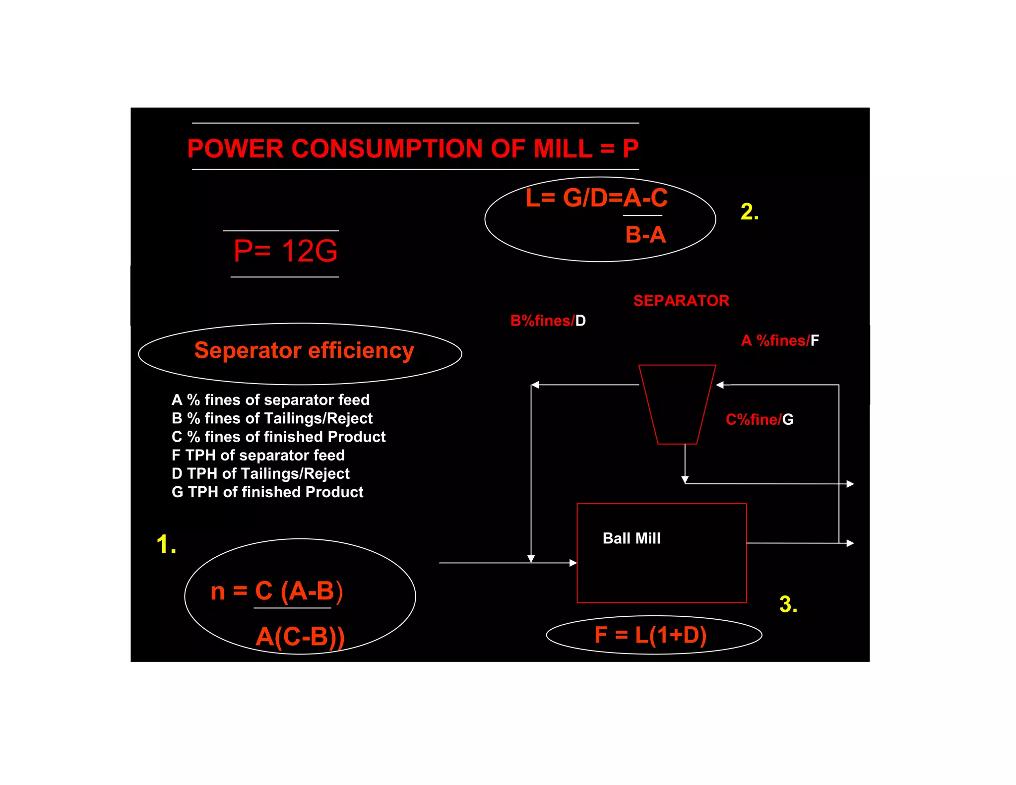
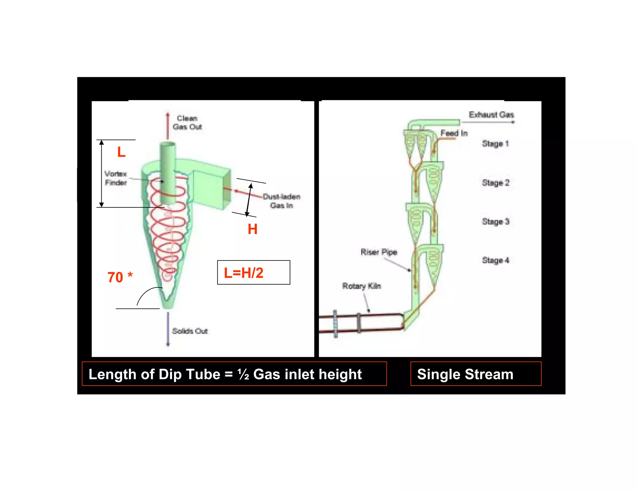
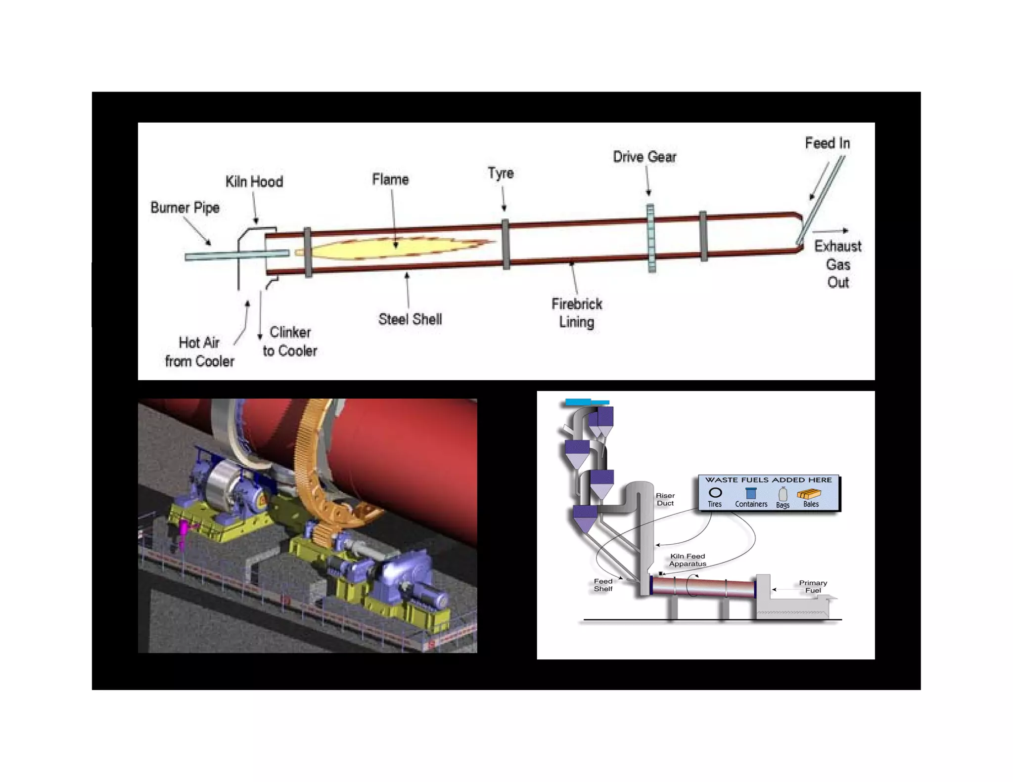
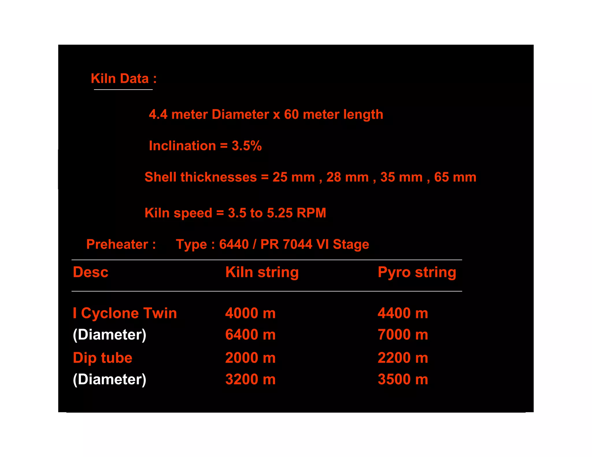
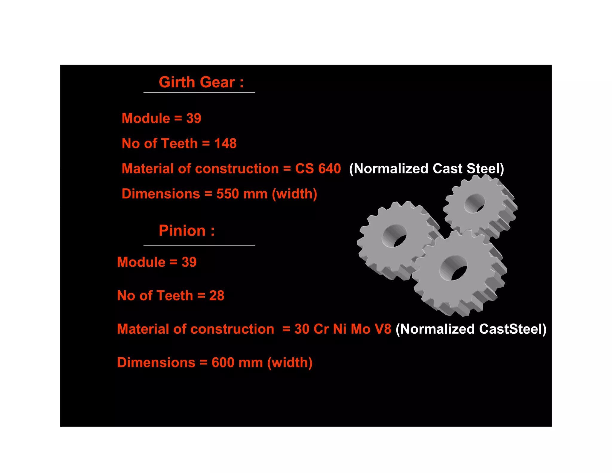
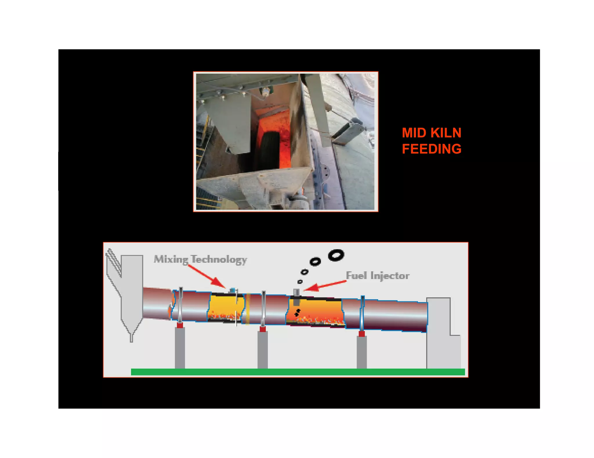
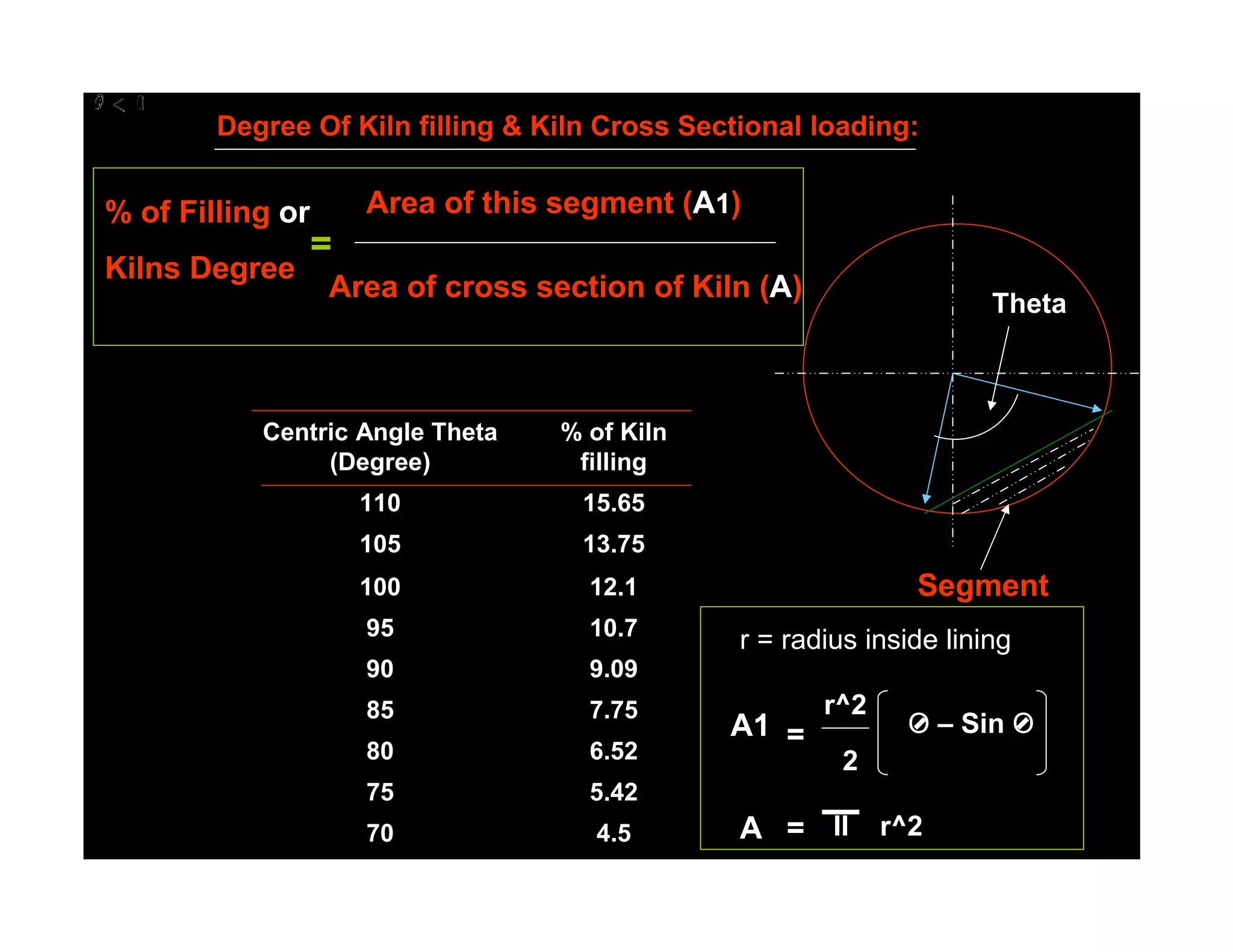
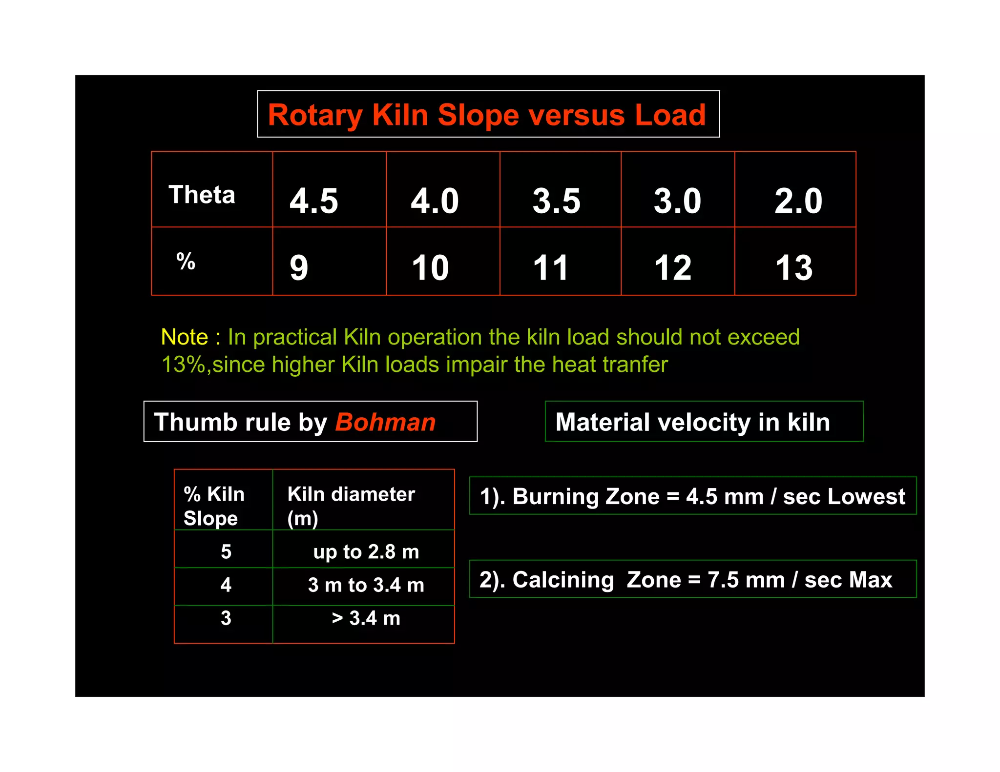
1. The residence time in a rotary kiln is calculated using a formula that considers the angle of repose of the limestone, length of the kiln, kiln inclination, effective diameter, and rotation speed.
2. A rotary kiln's capacity is determined by considering factors like the capacity of the ID fan, preheater cyclone design, proclaimed design and volume, kiln inclination and volume, kiln filling percentage, specific volume and thermal loading, and kiln drive capacity.
3. Important kiln parameters include the specific volume loading, specific thermal loading, cooler specific loading, and kiln percentage filling, which should be between 4-16%.
The Indian cement industry today stands at
260 MTPA capacity, with greater growth prospects
and promising future ahead. Cement industry has
been an excellent example of a fast growing sector
showing consistent and steady reduction in its
energy consumption. This has largely been
possible by steady and continuous improvement
across all equipments in cement manufacturing
process.
ENERGY MODELING OF THE PYROPROCESSING OF CLINKER IN A ROTARY CEMENT KILNISA Interchange
This paper highlights the efforts taken by the author in developing an Energy Model for the pyro-processing of Clinker production in a dry-process rotary cement kiln. In this paper this Energy Model is applied to a state of the art cement plant in a Far East Asian country. However this Energy Model is also applicable to all the modern dry process cement kilns. This model is based on actual field input data and site observations.
Installation of Refractory Materials in Rotary Kilns ”Essential principles"Refratechnik Group
This guide provides a brief overview of the steps for the installation materials in rotary kilns.
Please note that this guide does not claim to be complete, especially with regard to work safety and prevention of accidents.
For any further questions you may have, please do not hesitate to contact your local Refratechnik representative.
A Rotary kiln is a pyroprocessing device used to raise materials to a high temperature (calcination) in a continuous process. Materials produced using rotary kilns include: Cement. Lime.
The packing arrangement of a powder/granules bed depends on the nature and extent of friction among the particles/granules. The bulk volume of a prills depends on packing arrangement of particles, and the packing
arrangement in turn depends on inter-particular or inter-granular friction or
in other words, bulk volume of a given granules depends on the interparticular friction. Angle of repose, bulk density, particle distribution are other important parameters for this estimation
A new way to small-scale cement production.
There are no construction projects without cement, and no cement without LOESCHE vertical roller mills (VRM). Grinding of cement clinker and granulated blast furnace slag in vertical roller mills is a technology introduced by LOESCHE.
Since the first LOESCHE vertical roller mills came onto the market in 1928, countless numbers of them have been used in the cement industry across the world. Nowadays more than 2,000 LOESCHE mills are in operation worldwide.
Presentation from the AFCM cement conference taking place from 21-24 April in Hanoi, Vietnam: Introduction to the FLSmidth Operation and Maintenance concept
Output Equation; Main dimensions; Separation of D & L; Choice of Electric and Magnetic Loadings; Magnetic circuit calculations; Carter’s Coefficient; Net length of Iron; Real and Apparent flux densities; Selection of No. of poles; Design of Armature; Design of Commutator and brushes; Performance prediction using design values.
Design of Primary & auxiliary equipment of Diethyl ether production plant. Process & mechanical design of Reactor, Heat exchanger, Distillation column.
HOT TOPIC
TON OF REFRIGERATION,
WORK, U FACTOR, LRA (Locked rotor amps)
RPM of motor, HEAT FORMULA, GAS PIPING (Sizing – CF/hr.), CALCULATING OIL NOZZLE SIZE (GPH):
PYTHAGOREAN THEOREM, Linear Measurement Equivalents (U.S. Conventional - SI Metric)
This MathCAD file report predicts the transient skin temperature of a missile as it traverses the different layers of the atmosphere. The heat transfer coefficient is function of the height, z,t of the missile since the pressure and temperature of the are function of z,
1. Residence time in Kiln “t” = 1.77 (Phy)^1/2 L
________________
Alpha* D*N
Phy =Angle of repose for lime stone
~ 36 Degree
L = length of Kiln in meter
Alpha = Kiln inclination in %
D = Effective diameter of Kiln in meter
N = Rotation per minute rpm
2. Kiln Kiln
Inlet Outlet
A B C D E
Preheater Zone = 1 min A 7.5m/sec
Mat velo Max
Precalcination Zone = 2 min B
t = 20 -28
= Minutes
Calcination Zone = 10-12 min C
Burning Zone = 6 – 8 min D
4.5m/sec
Cooling Zone = 2 min F Mat Velo Min
5. SILICA RATIO
SiO2
SR =
(Al2O3 + Fe2O3)
2.2 > SR < 2.6
= =
6. ALUMINA RATIO
Al2O3
AR =
Fe2O3
1.5 > AR < 2.5
= =
AR < 1.5 IS CALLED FERROCEMENTS
AR = 0.637 IS CALLED FERRARI CEMENT
7. CALORIFIC VALUE OF COAL
LHV = HHV – 50.1H – 5.6 M – 0.191O
LHV = LOW HEATING VALUE Kcal /Kg
HHV = HIGH HEATING VALUE Kcal /Kg
M = % MOISTURE H = % HYDROGEN O = % OXYGEN
KCal / Kg x 4.187 x 10^(-3) = MJ/Kg ultimate
analysis
KCal / Kg x 1.8 = Btu / lb
8. COAL USED IN CEMENT INDUSTRY
• LHV = 6500 – 7000 Kcal / Kg
• ASH = 12~15 %
• VOLATILE MATERIAL = 18~ 22 %
• MOISTURE = UP TO 12 %
9. D =Diameter in
Meter
L = Length in meter
WEIGHT OF CYLINDRICAL( kiln) SHELL = W
W = Pi x (L) x (D) x thk (mm) x 7.85 Metric Tons
10. THERMAL EXPANSION OF SHELL Skin Temperature
Diagram
A = Alpha x TxL L= Length of (Kiln) Shell
=L1 + L2
Alpha for steel (coefficient of linear expansion = 1.2x 10^ (-5)
mm per Meter
T= dT =( Average temp – Ambient temp) Degre centigrade
L1 L2
A1= (T2a+T1)/2 - T X L1
T2bb
A1= (T2b+T1)/2 - T X L2 T1
Ambient temp = T T2a
A = A1 +A2
11. IMPOTANT PARAMETERS
KILN SPECIFIC VOLUME LOADING = TPD/ m3
or Specific Kiln capacity ~ 2.3 t / m3 at Kiln circumferential
speed = 50 cm / sec
KILN SPECIFIC THERMAL LOADING = Kcal / m2.hr
Specific Kiln thermal loading Qp = 1.4 x 10 ^ 6 x D Kcal / m2. hr
Qp should not exceed 3.46 x 10^6 Kcal/m^2.hr
COOLER SPECIFIC LOADING or Specific Cooler Capacity =
TPD/ m2 = 38 -43 metric ton of clinker per m^2 .24 hr
KILN % FILLING = 04 % Min - 16% Max
12. KILN CAPACITY ASSESMENT
•Capacity of ID fan.
•Preheater cyclone design.
•Proclaimed Design & Volume.
•Kiln inclination & Volume.
•Kiln % filling, Specific volume loading &.Thermal
loading.
•Kiln Drive capacity.
•System Design, Ducts, GCT, fan position & ESP.
13. For Gears:
Pitch Diameter = Module x No. of Teeth
Blank Diameter = Module x (No of Teeth+2)
For Airslide Cloth
• Fabric Polyester 100%.
• Min=140*C & Max = 260*C.
• Permeability = 400m3/hr-m2 or 6m3/min-m2. at 80mbar
• Tensile strength : WEFT = 1200 Kg/cm2 : WARP = 600 Kg/cm2
• Air Required = 2.5-3.0(Closed type), (2 Cone silo Bins),(1.5Open
Type)
14. PH fan-1 Twin cyclones PH fan-2 Twin cyclones
IA IB
II
III
IV
Riser
Duct
V KILN STRING
VI
V
950*C
T.A.Duct
SLC
PYRO STRING KILN
I Girth gear II III
16. D Theta’
Mill charging:
Theta
H
H = 0.16D
MILL CROSS SECTION
Dynamic Angle of Repose = 35 degree 20 minutes with Horizontal (Theta )
OR
Dynamic Angle of Repose = 54 degree 40 minutes with Vertical (Theta )’
17. GRINDING MEDIA LOAD “ G”
G = gm.Sy.Pi. (R)^2.L
4
Constants:
Sy = specific gravity of
G = 4620(R)^2.L ball 7.8-7.9 Ton / m3
gm = Bulk density of charge
TAGGARTS FORMULA 4.5 Ton / m3
.
Pi = 22/7 or 3.14
18. POWER CONSUMPTION OF MILL = P
L= G/D=A-C
2.
B-A
P= 12G
SEPARATOR
B%fines/D
A %fines/F
Seperator efficiency
A % fines of separator feed s
B % fines of Tailings/Reject C%fine/G
C % fines of finished Product
F TPH of separator feed
D TPH of Tailings/Reject
G TPH of finished Product
Ball Mill
1.
n = C (A-B) 3.
A(C-B)) F = L(1+D)
19. L/D=3 Two Compartment Mill
L / D = 4.5 Three Compartment Mill
I – Chamber Drag Peb Liners
Carman Lining
Classifying Slegton –
Liners Magotteaux
Lining
Lining
FLS Lining
28. Kiln Data :
4.4 meter Diameter x 60 meter length
Inclination = 3.5%
Shell thicknesses = 25 mm , 28 mm , 35 mm , 65 mm
Kiln speed = 3.5 to 5.25 RPM
Preheater : Type : 6440 / PR 7044 VI Stage
Desc Kiln string Pyro string
I Cyclone Twin 4000 m 4400 m
(Diameter) 6400 m 7000 m
Dip tube 2000 m 2200 m
(Diameter) 3200 m 3500 m
29. Girth Gear :
Module = 39
No of Teeth = 148
Material of construction = CS 640 (Normalized Cast Steel)
Dimensions = 550 mm (width)
Pinion :
Module = 39
No of Teeth = 28
Material of construction = 30 Cr Ni Mo V8 (Normalized CastSteel)
Dimensions = 600 mm (width)
30. Tyre Assemblies three no’s :
Material of construction = GS 24 Mn 5 (Normalized Cast Steel)
Dimensions = 5620 OD x 4581 ID x 775 (width)
Main Drive
Supporting Rollers Assemblies three no’s :
Material of construction = CS 640 (Normalized Cast Steel)
Dimensions = 5620 OD x 4581 ID x 775 (width)
Tyre Kiln
Supporting Roller Shell
Girth Gear
Pinion
31. Kiln Main Drive : Gear box = SDN 800
Ratio = 54.35:1
RWN-500
Motor KW = 710
Aux G.B SDA 250 54.35: 1 Input RPM = 100 - 1000
Motor 30 KW ; 1500 RPM
Motor G.B
G.B Motor
RWB-178 Pinion
Kiln Axis
Concord Alingnomatic
Geared Coupling
G.G
36. Degree Of Kiln filling & Kiln Cross Sectional loading:
% of Filling or Area of this segment (A1)
=
Kilns Degree
Area of cross section of Kiln (A)
Theta
Centric Angle Theta % of Kiln
(Degree) filling
110 15.65
105 13.75
100 12.1 Segment
95 10.7
r = radius inside lining
90 9.09
85 7.75 r^2
A1 = O – Sin O
80 6.52 2
75 5.42
70 4.5 A = II r^2
37. Rotary Kiln Slope versus Load
Theta 4.5 4.0 3.5 3.0 2.0
% 9 10 11 12 13
Note : In practical Kiln operation the kiln load should not exceed
13%,since higher Kiln loads impair the heat tranfer
Thumb rule by Bohman Material velocity in kiln
% Kiln Kiln diameter 1). Burning Zone = 4.5 mm / sec Lowest
Slope (m)
5 up to 2.8 m
4 3 m to 3.4 m 2). Calcining Zone = 7.5 mm / sec Max
3 > 3.4 m
38. Rotary Kiln power input calculation :
W x bd x td x N x F x 0.0000092
1
H.P =
rd
W = Total vertical load on all roller shaft bearing,lb
bd = roller shaft bearing diameter , inches Note :
This is Frictional
rd = roller diameter , inches 1
Horse Power
td = tire or riding rind diameter , inches
N = rpm of Kiln shell
P = Coefficient or friction of roller bearings , 0.018 for oil
lub bearings & 0.06 for grease lub bearings
39. This is Load Horse
2
Horse Power
H.P = (D x Sin O) ^3 x N x L x K 2
D = Kiln dia .inside lining , ft
Sin O = read from diagram depending on %Load
N = rpm of Kiln shell
L = length of kiln in ft
K = 0.00076 Total power = 1 + 2
42. =
V Z Cos O
D–a–b X K% = Z
2 H = Z Sine O
Kiln Diameter = D
Kiln lining thickness = a
Kiln Coating thickness = b
Angle of Repose of kiln load = O = 40* say
Kiln Load = K % Value from table below
Depth of bed in Kiln = Y % To be measured
Kiln load = K % 5 6 7 8 9 10 11 12 13 14 15
Depth of
material bed in
Kiln = Y % 9.75 11 12.2 13.4 14.5 15.6 16.7 17.7 1.8.8 19.8 21
43. Standard Coal Factor : SCF
To determine the approximate combustion air needed to burn
a given unit wt of coal, formula given below can be used when
no ultimate analysis is available. The combustion air
requirement include here 5% of excess air
100 - a B
= SCF
100 7000
Kg of Air = 10.478 SCF
Kg of Coal
a = % Moisture in coal ( as fired )
B = Heat value of coal ( Kcal / kg as fired )
44. % Loading of Kiln : Theoretical Flame
Temperature fuel oil :
Cxfxt Q
T =
L = Vg x Cp
dxV
Q = heating value of
oil , K cal / kg
C = Capacity of Kiln Ton / hr Vg = Volume of
combustion gases ,
f = Ton (Kg) dry feed / Ton ( kg) of Clinker
Nm^3 / Kg
t = residence time
Cp = Specific heat of
d = Bulk density of dry feed ton (Kg) / m^3 combustion gases
=0.40 at 2000*C for
V = Internal volume of kiln in m^3
fuel class “S”
45. Rotary kiln Capacity
Martin’s Formula :
C = 2.826 v X D^3
Vg
C = Kiln Capacity Ton / Hr
V = Gas Velocity in gas discharge end , m / sec
Vg = specific gas volume , m^3 / kg clinker
D = Kiln Diameter on Bricks, m
46. Heat capacity of Rotary kiln
1 Q = 1.1 x 10 ^ 6 x D ^3 (Kcal / hr)
D = Mean inside Kiln Diameter on Bricks, m
2 Kiln Thermal loading at cross
section of burning zone = Qp = = Q / Fp
Fp = 0.785 x D^2 Inside cross-section of the kiln
burning zone m^2 where D is kiln shell diameter
Q p = 1.4 x 10 ^ 6 x D Kcal / m^2.hr
Qp should not exceed 3.46 x 10 ^ 6 kcal / m2.hr
47. Heat transfer in cyclones preheater:
The rule is that the sizes of the gas ducts and of the
cyclone should be in accordance with the formula:
V^2
= Constant
ID ^ 5
V = Gas volume
ID = Inside Diameter of ducts /
cyclones respectively
48. Preheater cyclone sizing
(V) ^ 2 x Vt C
D = 0.536 4
P
Vt = V0 273 + t + K K = dust concentration in
Gas , grams / m^ 3
273
D = cyclone Diameter , m
V = Gas volume passimg cyclone , m ^ 3 / Sec
Vt = sp. gr. of gas at aver. Temp , Kg / m ^ 3
C = Coefficient for pressure drop = 110
P = Pressure drop in cyclone in mm WG
49. Small size high efficiency cyclone
L
H
70 * L=H/2
Length of Dip Tube = ½ Gas inlet height Single Stream
Pressure drop across cyclone = 55 – 60 mbar
50. Theoretical Heat consumption Q for
clinker burning :zur Strassen formula :
Constituent Constituent Multiplication Heat Cons Net
Name X % Factor Y kcal/kg
Al2O3 5.92 2.22 + 13.1 +
MgO 1.05 6.48*MgO6.48 + 6.8 527.4
CaO 63.91 7.646 + 488.7
H2O 3.2 5.86 + 18.8
_
SiO2 22.68 5.11 _ 117
118.4
Fe2O3 2.31 0.59 _ 1.4
Net % 99.27 Net Kcal / Kg = 409.0
Q = 2.22 Al203 + 6.48 MgO + 7.646 CaO + 5.86 H2O + 5.11 SiO2 + 0.59 Fe2O3
51. Thermal efficiency of cooler = E
A-B X 100
E=
A
A = Heat loss of clinker leaving the kiln
B = Heat loss of the clinker cooler
3250 (347 – K )
Secondary Air Temperature = t =
(X.n)
K = Heat loss of the cooler , Kcal/Kg clinker
X = Specific Heat consumption of the kiln , Kcal / Kg clinker
n = Excess Air number = 1.1
Cooler fans designed for Specific Volume of 3 – 3.15 st.m^3/Kg clinker
52. Cooling of kiln Exit Gases (GCT)
Kg / min.Exit gas x 0.25 ( t 1 – t 2) Kcal / min
Y=
H t2 – H t3
t1 = Temperature of Kiln exit gases
t2 = Temperature of gas to be achieved or maitained
t3 = temperature of water (15*C)
H t2 = Heat content of water at t2
H t3 = Heat content of water at t3
Y = Kg Water Spray / min