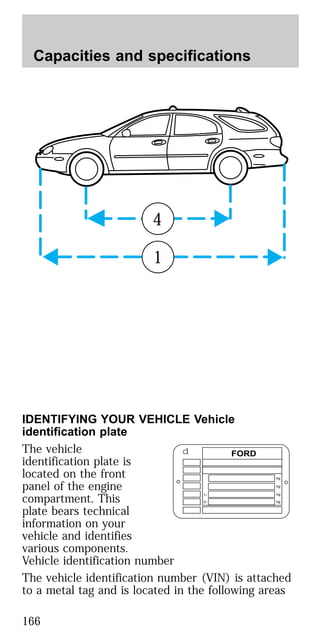
This document provides an overview of instrumentation, controls, features, and climate systems for a vehicle. It includes descriptions of the function of various dashboard gauges, lights, knobs, and switches to control elements like the headlights, climate system, and more. Warnings and cautions are highlighted. The climate control system section explains the operation of the manual heating and air conditioning system, including the fan speed control, mode selector, and temperature control.


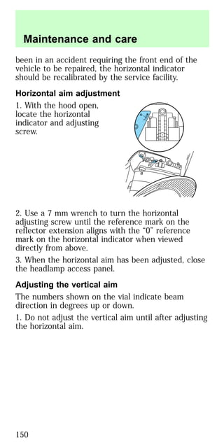
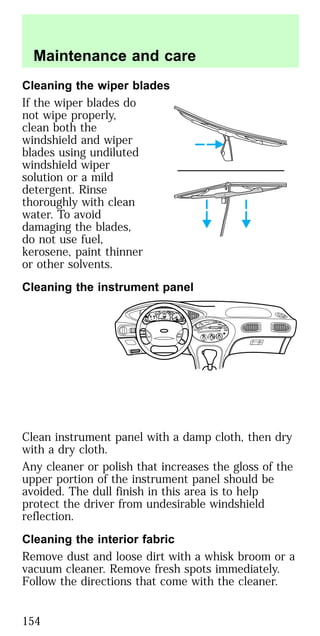
![IMPORTANT CHILD RESTRAINT PRECAUTIONS
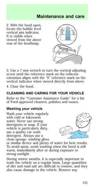
You are required by law to use safety restraints for
children in the U.S. and Canada. If small children
ride in your vehicle (generally children who are four
years old or younger and who weigh 18 kg [40 lbs]
or less), you must put them in safety seats made
especially for children. Check your local and state or
provincial laws for specific requirements regarding
the safety of children in your vehicle.
Never let a passenger hold a child on his or
her lap while the vehicle is moving. The
passenger cannot protect the child from injury in a
collision.
Always follow the instructions and warnings that
come with any infant or child restraint you might
use.
When possible, place children in the rear seat of
your vehicle. Accident statistics suggest that
children are safer when properly restrained in the
rear seating positions than in the front seating
position.
CHILDREN AND SAFETY BELTS
Children who are too large for child safety seats (as
specified by your child safety seat manufacturer)
should always wear safety belts.
Follow all the important safety restraint and air bag
precautions that apply to adult passengers in your
vehicle.
If the shoulder belt portion of a combination lap and
shoulder belt can be positioned so it does not cross
or rest in front of the child’s face or neck, the child
should wear the lap and shoulder belt. Moving the
child closer to the center of the vehicle may help
provide a good shoulder belt fit.
If the shoulder belt cannot be properly positioned:
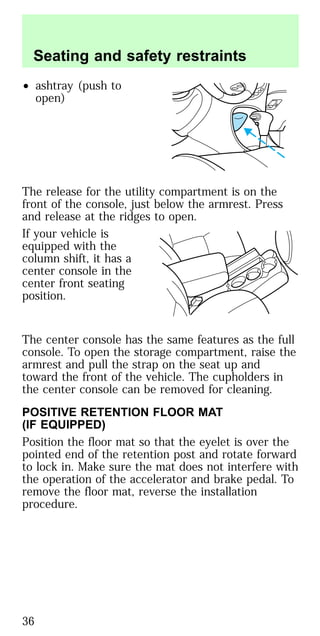
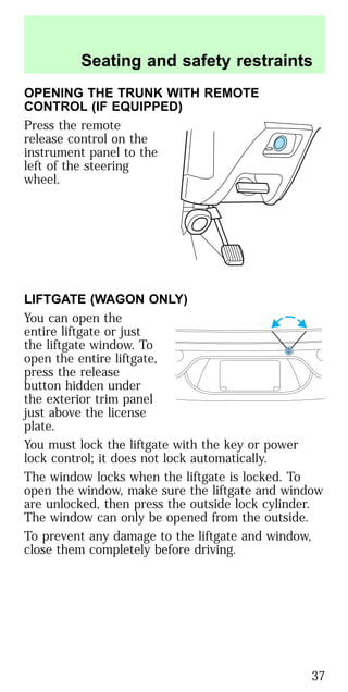
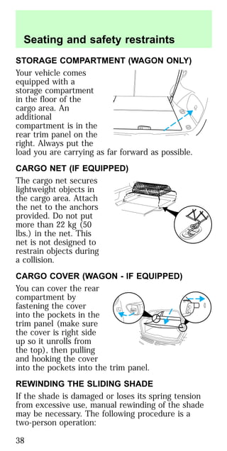
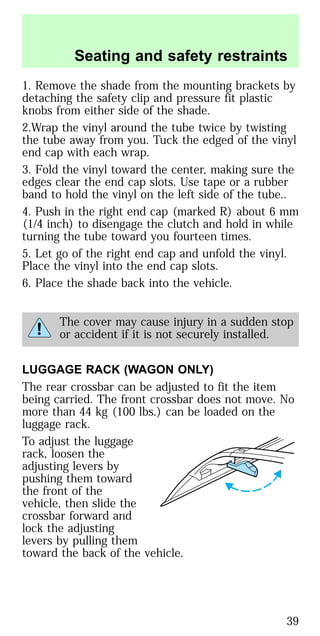
Seating and safety restraints
67](https://image.slidesharecdn.com/97taurus-140906074600-phpapp02/85/97taurus-66-320.jpg)

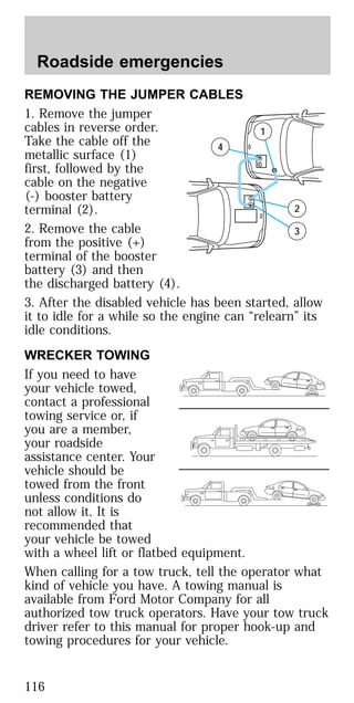
![3. Connect the positive
(+) terminal of the
discharged battery (1)
to the positive (+)
terminal of the booster
battery (2).
4. Connect one end of
the second lead to the
negative (-) terminal of
the booster battery (3)
and the other end to a
metal part of the
engine to be started (4), not to the negative (-)
terminal of the discharged battery.
5. Make sure that the jump leads are clear of moving
parts of the engine.
Do not connect the end of the second cable
to the negative ([-]) terminal of the battery
to be jumped. A spark may cause an explosion of
the gases that surround the battery.
JUMP STARTING
1. Start the booster vehicle and run the engine at
moderately increased speed.
2. Start the engine of the vehicle with the
discharged battery.
3. Once the engine has been started, run both
vehicles for a further three minutes before
disconnecting the leads.
+
–
+
–
3
2
1
4
Roadside emergencies
115](https://image.slidesharecdn.com/97taurus-140906074600-phpapp02/85/97taurus-114-320.jpg)
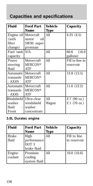
![Coolant refill capacity
To find out how much fluid your vehicle’s cooling
system can hold, refer to Refill capacities in the
Capacities and specifications chapter.
Have your dealer check the engine cooling system
for leaks if you have to add more than a liter (quart)
of engine coolant per month.
Severe winter climate
If you drive in extremely cold climates [less than
–36°C (–34°F)], it may be necessary to increase the
coolant concentration above 50%. Refer to the chart
on the coolant container to ensure the coolant
concentration in your vehicle is such that the coolant
will not freeze at the temperature level in which you
drive during winter months. Never increase the
engine coolant concentration above 60%. Leave a
50/50 mixture of engine coolant and water in your
vehicle year-round in non-extreme climates.
CHECKING AND ADDING POWER STEERING
FLUID
Check the power
steering fluid at least
twice a year. If adding
fluid is necessary, use
only Mercon ATF
power steering fluid.
1. Start the engine and let it run until it reaches
normal operating temperature (the engine coolant
gauge will be near the center of the NORMAL band).
2. While the engine idles, turn the steering wheel
left and right several times.
3. Turn the engine off.
Maintenance and care
129](https://image.slidesharecdn.com/97taurus-140906074600-phpapp02/85/97taurus-128-320.jpg)