This document provides an overview of setting up co-simulation between ANSYS Mechanical and ANSYS Fluent using System Coupling. It discusses the necessary setup steps in Mechanical including analysis settings, fluid-solid interfaces, and output controls. It also covers the Fluent setup, including defining dynamic mesh zones, solution stabilization options, and notes on fluid compressibility. Finally, it addresses the System Coupling setup for defining data transfers and solution controls between the two solvers.


![© 2011 ANSYS, Inc. January 4, 201335 Release 14.5
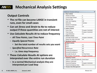
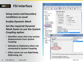
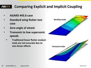
Comparing Explicit and Implicit Coupling
• Comparing the predicted flutter
frequency versus time step size
for different Coupling (Stagger)
Iterations
• Explicit coupling (1 Stagger)
requires a smaller time step for
accurate results
• The physics determines the time
step size with implicit coupling
• Large time step with 5 coupling
iterations and small time step
with 1 coupling iteration both
give good results
• Large time step case runs 4 times
faster – implicit coupling reduces
CPU time
• Explicit coupling is unstable at
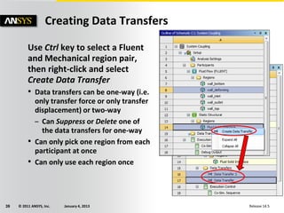
larger time steps
12
13
14
15
16
1.E-04 1.E-03 1.E-02
Time stepsize [s]
Flutterfrequency[Hz]
5 Stagger
3 Stagger
1 Stagger
-6.E-03
-4.E-03
-2.E-03
0.E+00
2.E-03
4.E-03
6.E-03
0 0.05 0.1 0.15 0.2 0.25
Time [s]
Amplitude[]
dt=0.00025 [s], 1 Stagger
dt=0.005 [s], 5 Stagger
dt=0.005 [s], 1 Stagger](https://image.slidesharecdn.com/fluent-fsi14-150404050432-conversion-gate01/85/Fluent-fsi-14-5-lect-03_co_simulation_setup-1-35-320.jpg)


![Modeling and Structural Analysis of a Wing [FSI ANSYS&MATLAB]](https://cdn.slidesharecdn.com/ss_thumbnails/finalreport-191222214155-thumbnail.jpg?width=640&height=640&fit=bounds)