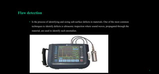
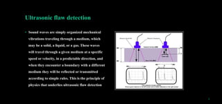
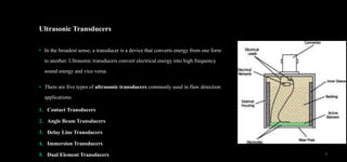
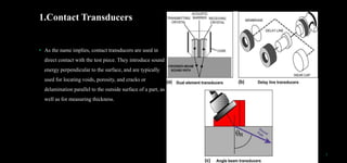
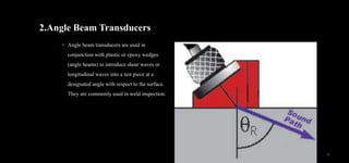
2. SCOPE
• Introduction
• Definitions (Flaw And Flaw Detection )
• Ultrasonic Flaw Detection
• Structural Integrity
• How To Calculate The Integrity Of Structures
• Reference
2
3. FLAW DETECTION OF ENGINEERING MATERIALS
• Introduction
flaw is “an imperfection, often concealed, that impairs soundness”. Here, a flaw is a heterogeneity that
disrupts the theoretical order and introduces a discontinuity or a singularity.
3
4. Flaw detection
• Is the process of identifying and sizing sub-surface defects in materials. One of the most common
techniques to identify defects is ultrasonic inspection where sound waves, propagated through the
material, are used to identify such anomalies.
4
5. Ultrasonic flaw detection
• Sound waves are simply organized mechanical
vibrations traveling through a medium, which
may be a solid, a liquid, or a gas. These waves
will travel through a given medium at a specific
speed or velocity, in a predictable direction, and
when they encounter a boundary with a different
medium they will be reflected or transmitted
according to simple rules. This is the principle of
physics that underlies ultrasonic flaw detection
5
6. Ultrasonic Transducers
• In the broadest sense, a transducer is a device that converts energy from one form
to another. Ultrasonic transducers convert electrical energy into high frequency
sound energy and vice versa.
• There are five types of ultrasonic transducers commonly used in flaw detection
applications:
1. Contact Transducers
2. Angle Beam Transducers
3. Delay Line Transducers
4. Immersion Transducers
5. Dual Element Transducers 6
7. 1.Contact Transducers
• As the name implies, contact transducers are used in
direct contact with the test piece. They introduce sound
energy perpendicular to the surface, and are typically
used for locating voids, porosity, and cracks or
delamination parallel to the outside surface of a part, as
well as for measuring thickness.
7
8. 2.Angle Beam Transducers
• Angle beam transducers are used in
conjunction with plastic or epoxy wedges
(angle beams) to introduce shear waves or
longitudinal waves into a test piece at a
designated angle with respect to the surface.
They are commonly used in weld inspection.
8
9. 3.Delay Line Transducers
• Delay line transducers incorporate a short plastic
waveguide or delay line between the active element
and the test piece. They are used to improve near
surface resolution and in high temperature testing,
where the delay line protects the active element from
thermal damage.
9
10. 4.Immersion Transducers
• Immersion transducers are designed to couple sound
energy into the test piece through a water column or
water bath. They are used in automated scanning
applications and in situations where a sharply focused
beam is needed to improve flaw resolution.
10
11. 5.Dual Element Transducers
• Dual element transducers utilize separate transmitter
and receiver elements in a single assembly. They are
often used in applications involving rough surfaces,
coarse grained materials, detection of pitting or
porosity, and they offer good high temperature
tolerance as well.
11
12. Ultrasonic Flaw Detectors
• Modern ultrasonic flaw detectors such as
the EPOCH series are small, portable,
microprocessor-based instruments suitable for both
shop and field use. They generate and display an
ultrasonic waveform that is interpreted by a trained
operator, often with the aid of analysis software, to
locate and categorize flaws in test pieces.
12
13. STRUCTURAL INTEGRITY
• Structural integrity is an engineering field that helps ensure that either a structure or structural component is fit for
purpose under normal operational conditions and is safe even should conditions exceed that of the original design.
This includes supporting its own weight, aiming to prevent deformation, breaking and catastrophic failure throughout its
predicted lifetime.
• Integrity is not just a case of good design; it needs to be maintained for the life of a structure. This requires inspection
and maintenance at periodic intervals. Engineers ensure structures are safe, reliable and perform their designed
function throughout their lifetime.
13
14. How to determine structural integrity
To determine structural integrity we use surface hardness test, ultrasonic pulse velocity test, impact
echo test, impulse response test etc. For us let focus the two among these tests.
• Surface hardness test, whereby rebound of spring driven by mass is measured after its impact with
concrete surface.
• Ultrasonic pulse velocity test .this is conducted by passing a pulse of ultrasonic through concrete to
be tested and measuring time taken by pulse to get through structure. Higher velocity indicate good
quality and continuity of material while lower velocity may indicate concrete with many cracks or
voids.
14
15. What are the Causes of Structural Failure?
• Structural failure can occur from a range of
different sources. The type of failure is often
associated with the industry, environment
and application of the structure. The primary
reasons for the failure are as follows:
1. Weak structures
15
17. 3 .Improper environmental considerations.
Engineers may neglect mitigating features for certain
environmental conditions, such as natural disasters.
17
4.Improper operational conditions.
The structure is not used for its intended purpose.
18. How to Calculate the Integrity of Structures
Engineers combine an array of considerations into the design process, such as materials performance, stress analysis and
fracture mechanics.
Once built, a construction will need inspection and maintenance to maintain its integrity. To do this, an engineer might:
Carry out inspections to identify damage. This might involve the use of non-destructive testing (NDT).
Check that a structure has been built according to the appropriate designs, procedures and standards.
Check that a structure is being used appropriately for the environment designed for.
Recommend and design modifications to address areas of concern.
18
19. REREFENCES
1. Trelinski M., “Inspection of CANDU Reactor Pressure Tubes Using Ultrasonics”, Proceedings of 17th World
Conference on Nondestructive Testing, Shanghai, China, October 2008.
2. Karp Elson A., “Quasi-Tomographic” Ultrasonic Technique for Tube Inspection”, The journal of NDT, vol. 10, No. 6,
June 2005.
3. Karp Elson A., “Quasi-Tomographic Ultrasonic Inspection of Tubes”, Proceedings of IV Pan-American Conference on
NDT, Buenos-Aires, Argentina, October 2007.
4. Karp Elson A., “Ultrasonic Detection of Cracks in Pressure Tubes”, Proceedings of 32nd Canadian Nuclear Society
Conference, Niagara Falls, Canada, June 2011.
5. Karp Elson A., “Improved Flaw Characterization and Sizing in Pressure Tubes”, The journal of NDT, vol. 17, No. 9,
September 2012.
6. Karp Elson A., “Ultrasonic Detection of Dry Contact between Metal Parts”, The journal of NDT, vol. 17, No. 5, May
2012.
19