Flame and smoke estimation for fire detection in videos based on optical flow and neural networks
•
1 like•816 views

IJRET : International Journal of Research in Engineering and Technology is an international peer reviewed, online journal published by eSAT Publishing House for the enhancement of research in various disciplines of Engineering and Technology. The aim and scope of the journal is to provide an academic medium and an important reference for the advancement and dissemination of research results that support high-level learning, teaching and research in the fields of Engineering and Technology. We bring together Scientists, Academician, Field Engineers, Scholars and Students of related fields of Engineering and Technology.
![IJRET: International Journal of Research in Engineering and Technology eISSN: 2319-1163 | pISSN: 2321-7308
_______________________________________________________________________________________
Volume: 03 Issue: 08 | Aug-2014, Available @ http://www.ijret.org 325
The system consists of mainly two modules, one for identifying whether flame is present in the frame and other module for finding whether smoke is present in the frame. The flame based method makes use of OMT and NSD methods for optical flow vector creation. The OMT method is successful for modeling fire with dynamic texture while, NSD method is used for modeling saturated fire blobs. In smoke based module pyramidal Lucas-Kanade [2] optical flow method is being used. Compared to Horn and Schunck method, Lucas-Kanade method is very suitable for modeling smoke. The pyramidal Lucas-Kanade model is suitable for modeling large motion objects very effectively rather than Lucas-Kanade without pyramids. 3. MODULES The system mainly contains two modules,
Flame detection module
Smoke detection module
3.1 Flame Detection Module The flame detection module will give as output whether flame is present in the frame. The module works by considering two consecutive frames in the video and all processings are done for each of the frame set. The processing start by converting the input RGB frames into frames in HSV color space. Then a generalized mass transformation is applied for each of the frame where it works on color basis, which is suitable for segmenting foreground from the background. Next optical flow vectors are being calculated for the image produced after generalized mass transformation. Then the less motion pixels are eliminated to avoid the processing overhead by analyzing the magnitude of the flow vector. After that four features are being calculated by analyzing the flow vectors. Finally a feed forward neural network is used for feature classification. In the testing case the trained neural network will give the probability of presence of flame in the frame. 3.1.1 Selection of Consecutive Frames The processing starts by taking consecutive frames in the video. For a frame 푖, (푖−1)푡ℎ frame is considered as the consecutive frame. Two frames are being selected since the optical flow vector is being calculated for frame 푖 based on (푖−1)푡ℎ frame. The frames should be resized to 240∗240 resolution.
Fig -2: Consecutive Frames
3.1.2 RGB to HSV Transformation
The resized frames are converted into frames in HSV color space. For that built in function rgb2hsv is being used. H, S and V are hue, saturation and value which represent the type, purity and brightness of a color.
3.1.3 Color Based Transformation Generalized mass of a pixel is represented by the similarity to the center fire color in the HSV color space. The center fire color is a fully saturated and bright orange. Generalized mass is based on flame color, which is suitable for segmenting foreground and background. Generalized mass image can be computed as, 퐼=(1−(1+exp(−푎.(min{ 퐻푐−퐻 ,1−|퐻푐−퐻|}−푏)))^−1).푆.푉 where 푎=100,푏=0.11,퐻푐=0.083 and 퐻,푆,푉∈[0,1]. In the new color transformed image that is formed high values will be generated for those colors in the fire color range.
Fig -3: Color Transformed Image 3.1.4 Optical Flow Vector Creation Optical flow is a method used for estimating motion of objects across a series of frames. The method is based on an assumption which states that points on the same object location (therefore the corresponding pixel values) have constant brightness over time. Two methods are being used for flow vector creation,
Optical Mass Transport (OMT) optical flow.
Non Smooth Data (NSD) optical flow.
Here for the flow vector creation first of all find the average intensity image as well as the difference image. For that gaussian smoothened color transformed image is being used, which is found by convoluting the image with a gaussian kernel of size 7. Then the central sparse matrix derivative operators 퐷푥 and 퐷푦 are found by convoluting the mean image with kernels of size 7 which are specially designed for finding the derivative of image along 푥 and 푦 directions respectively. The solution for OMT method is, 푢 = (∝I +퐴푇퐴)−1 (퐴푇푏) where 퐼 is the average image formed by taking the mean of gaussian smoothened current image and previous image. b = -퐼푡 where 퐼푡 is the difference of current image and previous image, which are gaussian smoothened and A=[ 퐷푥퐼 퐷푦퐼].](data:image/gif;base64,R0lGODlhAQABAIAAAAAAAP///yH5BAEAAAAALAAAAAABAAEAAAIBRAA7)
Recommended
Recommended
More Related Content
What's hot
What's hot (18)
Viewers also liked
Viewers also liked (20)
Similar to Flame and smoke estimation for fire detection in videos based on optical flow and neural networks
Similar to Flame and smoke estimation for fire detection in videos based on optical flow and neural networks (20)
More from eSAT Publishing House
More from eSAT Publishing House (20)
Recently uploaded
Recently uploaded (20)
Flame and smoke estimation for fire detection in videos based on optical flow and neural networks
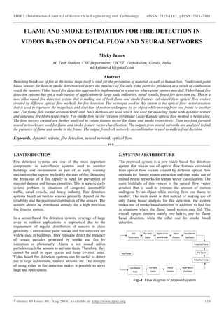
- 1. IJRET: International Journal of Research in Engineering and Technology eISSN: 2319-1163 | pISSN: 2321-7308 _______________________________________________________________________________________ Volume: 03 Issue: 08 | Aug-2014, Available @ http://www.ijret.org 324 FLAME AND SMOKE ESTIMATION FOR FIRE DETECTION IN VIDEOS BASED ON OPTICAL FLOW AND NEURAL NETWORKS Micky James M. Tech Student, CSE Department, VJCET, Vazhakulam, Kerala, India mickyjames43@gmail.com Abstract Detecting break out of fire at the initial stage itself is vital for the prevention of material as well as human loss. Traditional point based sensors for heat or smoke detection will detect the presence of fire only if the particles produced as a result of combustion reach the sensors. Video based fire detection approach is implemented in scenarios where point sensors may fail. Video based fire detection systems has got a wide variety of applications in large scale industries, naval vessels, forest fire detection etc. This is a new video based fire detection system that is making use of both flame and smoke features calculated from optical flow vectors created by different optical flow methods for fire detection. The technique used in this system is the optical flow vector creation that is used to represent the magnitude and direction of motion undergone by an object while moving from one frame to another one. For flame flow vector creation OMT and NSD methods are used which are used for modeling flame with dynamic texture and saturated fire blobs respectively. For smoke flow vector creation pyramidal Lucas-Kanade optical flow method is being used. The flow vectors created are further analyzed to create feature vector for flame and smoke respectively. Then two feed forward neural networks are used for flame and smoke feature vector classification. The outputs from neural networks are analyzed to find the presence of flame and smoke in the frame. The output from both networks in combination is used to make a final decision. Keywords: dynamic texture, fire detection, neural network, optical flow. --------------------------------------------------------------------***---------------------------------------------------------------------- 1. INTRODUCTION Fire detection systems are one of the most important components in surveillance systems used to monitor buildings and environment as part of an early warning mechanism that reports preferably the start of fire. Detecting the break-out of a fire rapidly is vital for prevention of material damage and human casualties. This is a particularly serious problem in situations of congested automobile traffic, naval vessels, and heavy industry. Fire detection systems based on built-in sensors primarily depend on the reliability and the positional distribution of the sensors. The sensors should be distributed densely for a high precision fire detector system. In a sensor-based fire detection system, coverage of large areas in outdoor applications is impractical due to the requirement of regular distribution of sensors in close proximity. Conventional point smoke and fire detectors are widely used in buildings. They typically detect the presence of certain particles generated by smoke and fire by ionization or photometry. Alarm is not issued unless particles reach the sensors to activate them. Therefore, they cannot be used in open spaces and large covered areas. Video based fire detection systems can be useful to detect fire in large auditoriums, tunnels, atriums, etc. The strength of using video in fire detection makes it possible to serve large and open spaces. 2. SYSTEM ARCHITECTURE The proposed system is a new video based fire detection system that makes use of optical flow features calculated from optical flow vectors created by different optical flow methods for feature vector extraction and then make use of trained neural networks for feature vector classification. The main highlight of this system is the optical flow vector creation that is used to estimate the amount of motion undergone by an object while moving from one frame to another. The main merit is that instead of making use of only flame based analysis for fire detection, the system makes use of smoke based detection in addition, to find fire in situations where the flame based system may fail. The overall system consists mainly two halves, one for flame based detection, while the other one for smoke based detection. Fig -1: Flow diagram of proposed system
- 2. IJRET: International Journal of Research in Engineering and Technology eISSN: 2319-1163 | pISSN: 2321-7308 _______________________________________________________________________________________ Volume: 03 Issue: 08 | Aug-2014, Available @ http://www.ijret.org 325 The system consists of mainly two modules, one for identifying whether flame is present in the frame and other module for finding whether smoke is present in the frame. The flame based method makes use of OMT and NSD methods for optical flow vector creation. The OMT method is successful for modeling fire with dynamic texture while, NSD method is used for modeling saturated fire blobs. In smoke based module pyramidal Lucas-Kanade [2] optical flow method is being used. Compared to Horn and Schunck method, Lucas-Kanade method is very suitable for modeling smoke. The pyramidal Lucas-Kanade model is suitable for modeling large motion objects very effectively rather than Lucas-Kanade without pyramids. 3. MODULES The system mainly contains two modules, Flame detection module Smoke detection module 3.1 Flame Detection Module The flame detection module will give as output whether flame is present in the frame. The module works by considering two consecutive frames in the video and all processings are done for each of the frame set. The processing start by converting the input RGB frames into frames in HSV color space. Then a generalized mass transformation is applied for each of the frame where it works on color basis, which is suitable for segmenting foreground from the background. Next optical flow vectors are being calculated for the image produced after generalized mass transformation. Then the less motion pixels are eliminated to avoid the processing overhead by analyzing the magnitude of the flow vector. After that four features are being calculated by analyzing the flow vectors. Finally a feed forward neural network is used for feature classification. In the testing case the trained neural network will give the probability of presence of flame in the frame. 3.1.1 Selection of Consecutive Frames The processing starts by taking consecutive frames in the video. For a frame 푖, (푖−1)푡ℎ frame is considered as the consecutive frame. Two frames are being selected since the optical flow vector is being calculated for frame 푖 based on (푖−1)푡ℎ frame. The frames should be resized to 240∗240 resolution. Fig -2: Consecutive Frames 3.1.2 RGB to HSV Transformation The resized frames are converted into frames in HSV color space. For that built in function rgb2hsv is being used. H, S and V are hue, saturation and value which represent the type, purity and brightness of a color. 3.1.3 Color Based Transformation Generalized mass of a pixel is represented by the similarity to the center fire color in the HSV color space. The center fire color is a fully saturated and bright orange. Generalized mass is based on flame color, which is suitable for segmenting foreground and background. Generalized mass image can be computed as, 퐼=(1−(1+exp(−푎.(min{ 퐻푐−퐻 ,1−|퐻푐−퐻|}−푏)))^−1).푆.푉 where 푎=100,푏=0.11,퐻푐=0.083 and 퐻,푆,푉∈[0,1]. In the new color transformed image that is formed high values will be generated for those colors in the fire color range. Fig -3: Color Transformed Image 3.1.4 Optical Flow Vector Creation Optical flow is a method used for estimating motion of objects across a series of frames. The method is based on an assumption which states that points on the same object location (therefore the corresponding pixel values) have constant brightness over time. Two methods are being used for flow vector creation, Optical Mass Transport (OMT) optical flow. Non Smooth Data (NSD) optical flow. Here for the flow vector creation first of all find the average intensity image as well as the difference image. For that gaussian smoothened color transformed image is being used, which is found by convoluting the image with a gaussian kernel of size 7. Then the central sparse matrix derivative operators 퐷푥 and 퐷푦 are found by convoluting the mean image with kernels of size 7 which are specially designed for finding the derivative of image along 푥 and 푦 directions respectively. The solution for OMT method is, 푢 = (∝I +퐴푇퐴)−1 (퐴푇푏) where 퐼 is the average image formed by taking the mean of gaussian smoothened current image and previous image. b = -퐼푡 where 퐼푡 is the difference of current image and previous image, which are gaussian smoothened and A=[ 퐷푥퐼 퐷푦퐼].
- 3. IJRET: International Journal of Research in Engineering and Technology eISSN: 2319-1163 | pISSN: 2321-7308 _______________________________________________________________________________________ Volume: 03 Issue: 08 | Aug-2014, Available @ http://www.ijret.org 326 In NSD method the solution is, u=− 퐼푥퐼푡 훻퐼 2 2+ 훼 v=− 퐼푦퐼푡 훻퐼 22 +훼 Here α is set as 0.4 and ∇퐼 is found by convoluting the mean image with a laplacian of gaussian kernel. 퐼푥 , 퐼푦 ,퐼푡 are image derivatives. For fire motion the flow vectors created are non smooth, while for rigid motion of object, smooth vectors are being created. Fig -4: OMT and NSD Optical Flow Vectors 3.1.5 Rejection of Non Essential Pixels To avoid unnecessary computation, non essential pixels have to be eliminated by analyzing the magnitude of the flow vectors that are being created. For that, first find the norm of the flow vector at each pixel position and then find the maximum value among them. Then find twenty percentage of that maximum value. If the norm of the flow vector in each of the pixel position is greater than the resultant value, that corresponding pixel is considered as essential one. Non essential pixel elimination should be done for both OMT and NSD method. Ω푒= 푥,푦 ∈Ω: 푢 (푥,푦) 2>0.2∗ Ω 푚푎푥 푢 2 3.1.6 Feature Extraction Four features are being extracted by analyzing the magnitude and direction of the flow vectors that are being created. In this stage consider only the essential pixels after the non essential pixel elimination. OMT Transport Energy Fire and other fire colored objects in the fire colored spectrum will produce high value for this feature. This feature measures the mean of the transport energy per pixel in the subregion. 푓1=( 퐼 2 푢 푂푀푇 22 )Ω푒 푚푒푎푛 NSD Flow Magnitude This value will be high for fire colored objects. NSD flow magnitude can be calculated by taking the mean of half of the square of the norm of NSD flow vectors calculated at each pixel position. 푓2=( 12 푢 푁푆퐷 22 )Ω푒 푚푒푎푛 OMT Source/Sink Matching The turbulent motion of fire will create flow vectors with vector source and sink. This feature is being calculated by convoluting the OMT flow vectors created with an ideal flow template of fire. 푓3= 푢푇∗ 푢푂푀푇 푢 푂푀푇 2 + 푣푇∗ 푣푂푀푇 푢 푂푀푇 2 Ω 푚푎푥 NSD Directional Variance This feature distinguishes the boundary motion of saturated fire blobs from rigidly moving objects. 푟= 푢2+푣2 represents flow vector magnitude and ɸ=arctan( 푣 푢 ) represents flow vector direction. The domain is discretized into wedges 푠푖, and each 푠푖 represents the ratio of pixels whose flow vector points in a direction between 2휋푖 푛 <ɸ≤ 2휋(푖+1) 푛 . 푓4=푣푎푟{푠푖,푖=0,…,푛−1} 3.1.7 Neural Network Based Classification During the testing phase, for classification of feature vector that is being created a trained feed forward neural network is being used. Training the neural network means performing a non-linear regression in the feature space to best separate the labeled training data into classes, such as fire or non fire. In the testing phase, a feature vector is supplied and the output is a probability that the feature vector is associated with a particular class. 3.2 Smoke Detection Module The smoke detection module will give as output, the probability of presence of smoke in the frame. The module works by considering two consecutive frames in the video and all processings are done for each of the frame set. The processing starts by converting input RGB frames into gray images. Then a smoke color model is being created. After that optical flow vectors are being created by Lucas-Kanade optical flow method for the image formed after pyramidal reduction. After that four features are being calculated by analyzing the flow vectors. Finally a feed forward neural network is used for feature classification. In the testing case the neural network will give as output whether smoke is present in the frame. 3.2.1 Selection of Consecutive Frames The processing starts by taking consecutive frames in the video. For frame 푖, (푖−1)푡ℎ frame is considered as the consecutive frame. Two frames are being selected since the optical flow vector is being calculated for frame 푖 based on (푖−1)푡ℎ frame. The frames should be resized to 240∗240 resolution.
- 4. IJRET: International Journal of Research in Engineering and Technology eISSN: 2319-1163 | pISSN: 2321-7308 _______________________________________________________________________________________ Volume: 03 Issue: 08 | Aug-2014, Available @ http://www.ijret.org 327 3.2.2 RGB to Gray Transformation The resized frames are converted into gray. For that built in function rgb2gray is used. 3.2.3 Smoke Model Creation In smoke module instead of color transformation, color based decision rule is being applied. Only those pixels in the current image that satisfies the decision rules will be retained and considered as pixels in the smoke color range. 푚푎푥=푚푎푥푖푚푢푚{푅 푖,푗 ,퐺 푖,푗 ,퐵(푖,푗)} 푚푖푛=푚푖푛푖푚푢푚{푅 푖,푗 ,퐺 푖,푗 ,퐵(푖,푗)} 퐼= 13{ 푅 푖,푗 ,퐺 푖,푗 ,퐵(푖,푗)} Rules are, 푚푎푥−푚푖푛<푎 and 푚1≤퐼≤푚2. where a varies from 5 to 20, 푚1 varies from 60 to 150 and 푚2 varies from 190 to 255. 3.2.4 Pyramidal Lucas-Kanade Optical Flow Vector Creation For smoke optical flow vector creation pyramidal Lucas- Kanade optical flow vector creation method is being used. Here pyramidal Lucas-Kanade up to level three is being used. The resolution of the resultant image will be one fourth of the original image. The reason behind opting pyramidal Lucas-Kanade is that, it will be more effective in representing fast motion. For the pyramid representation process, build pyramid representation of 퐼 recursively according to the equation below. 퐼퐿(푥,푦)= 14 퐼퐿−1 (2푥,2푦)+ 18 (퐼퐿−1 2푥−1,2푦 + 퐼퐿−1 2푥+1,2푦 +퐼퐿−1 2푥,2푦−1 +퐼퐿−1(2푥,2푦+ 1))+ 116 (퐼퐿−1 2푥−1,2푦−1 +퐼퐿−1 2푥−1,2푦+1 + 퐼퐿−1 2푥+1,2푦+1 +퐼퐿−1(2푥+1,2푦−1)) The result of the above equation is propagated to the next level 퐿−1, this procedure is repeated until the finest image resolution is reached. The Pyramidal Lucas-Kanade feature optical flow vector is, 푢 푝푦푟=퐺−1푏 where G = 푢푥 퐿+휔푥 푥=푢푥 퐿−휔푥 푢푦퐿 +휔푦 푦=푢푦퐿 −휔푦 퐼푥 2퐼푥퐼푦 퐼푥퐼푦퐼푦 2 푏 = 푢푥 퐿+휔푥 푥=푢푥 퐿−휔푥 푢푦퐿 +휔푦 푦=푢푦퐿 −휔푦 훿퐼.퐼푥 훿퐼.퐼푦 3.2.5 Feature Extraction Four features are being calculated from the optical flow vectors that are being created. In this stage consider only the essential pixels after the non essential pixel elimination. Transport Energy This feature measures the mean of the transport energy per pixel in the subregion. Smoke and other smoke colored objects in the smoke colored spectrum will produce high value for this feature. 푓1=( 퐼 2 푢 푝푦푟 22)Ω푒 푚푒푎푛 Flow Magnitude Flow magnitude can be calculated by taking the mean of half of the square of the norm of flow vectors calculated at each of the pixel position. 푓2= ( 12 푢 푝푦푟 22)Ω푒 푚푒푎푛 Source/Sink Matching Sink/Source Matching which is done to find the match of the optical flow vector that is being created with the ideal source flow template. Smoke motion tends to create flow vectors with vector sink and source. 푓3= 푢푇∗ 푢푝푦푟 푢 푝푦푟 2 + 푣푇∗ 푣푝푦푟 푢 푝푦푟 2 Ω 푚푎푥 Directional Variance This feature distinguishes the boundary motion of smoke from other rigidly moving objects. 푟= 푢푝푦푟 2+푣푝푦푟 2 represents flow vector magnitude and ɸ=arctan( 푣푝푦푟 푢푝푦푟 ) represents flow vector direction. The domain is discretized into wedges 푠푖 and each 푠푖 represents the ratio of pixels whose flow vector points in a direction between 2휋푖 푛 <ɸ≤ 2휋(푖+1) 푛 . 푓4=푣푎푟{푠푖,푖=0,…,푛−1} 3.2.6 Neural Network Based Classification During the testing phase, for classification of feature vector that is being created a trained feed forward neural network is being used. Training the neural network means performing a non-linear regression in the feature space to best separate the labeled training data into classes, such as smoke or non smoke. In the testing phase, a feature vector is supplied and
- 5. IJRET: International Journal of Research in Engineering and Technology eISSN: 2319-1163 | pISSN: 2321-7308 _______________________________________________________________________________________ Volume: 03 Issue: 08 | Aug-2014, Available @ http://www.ijret.org 328 the output is a probability that the feature vector is associated with a particular class. Fig -4: Combined Flame and Smoke Estimation 4. PERFORMANCE EVALUATION The proposed fire detection system has been evaluated and compared with an existing fire detection system [1]. The objective is to evaluate the detection rate of both systems and representing it with a bar graph. All the experiments were conducted on an Intel i3, 1.8GHz PC with 4 GB RAM. All the algorithms were implemented using MATLAB. 4.1 Comparison in Terms of Detection Rate The enhanced system is compared against an existing flame based fire detection system [1]. The enhanced fire detection is performing well than the existing system in cases where only smoke is present in the video, while flame is not present and also in conditions where flame is not clearly identifiable by the base system while the smoke is clearly visible and identifiable by the enhanced system. The performance is analyzed by plotting a bar graph, where one bar shows the performance of base system and other shows the performance of enhanced system. The performance is evaluated in real time based on the number of frames considered for evaluation. Chart -1: Detection Graph The system is being evaluated with various fire scenarios, where only smoke present, both flame and smoke present, only flame present, both flame and smoke not present. A video is considered where cloudy sunset condition is seen. In that case no detection of cloud as smoke occured. Also the light from the sun reflecting on the cloud is not detected as fire. In that case the system performed well. As second case a video containing only flame present is given as input. In that case the system clearly found no smoke is present, while flame is correctly detected except in one or two frames. Another video is given where only smoke is present. In that case the flame detection module showed no flame is present while, the smoke detection module worked correctly except in two or three cases. As fourth case a video containing both flame and smoke is given, in that case the enhanced system performed well because in cases where the flame detection module gave false detections, the smoke detection module produced correct output and so the enhanced system gave more fire detections in the frames considered. Here the chart shows the detection rate for a video containing both flame and smoke present. In that video 100 frames were considered, 99 were taken for plotting graph since, fire detection is not done for the first frame. Out of the 99 frames, in all cases the smoke module performed well while the flame module failed in many situations. So the performance of the overall system is improved since in the enhanced system the smoke module is detecting fire in those cases where flame module fails. 5. CONCLUSIONS The proposed system is a combined flame and smoke estimation system for fire detection. The system is combining neural network based outputs from both flame and smoke modules to make a final decision, i.e fire with both smoke and flame, fire with smoke and non flame, fire with flame and non smoke and non fire condition. By combining outputs from both these modules the proposed system will reliably detect fire. The enhanced system is performing well than the existing system [1] in terms of detection rate. The main highlight is the usuage of optical flow methods in both modules. The system is performing well in situations where the impact of smoke is greater than that of flame. REFERENCES [1]. M. Muller, P. Karasev, A. Tannenbaum and I. Kolesov, “Optical flow estimation for flame detection in videos”, IEEE Trans. Image Proces,. vol.22, no.7, July 2013. [2]. Jean-Yves Bouguet, “Pyramidal implementation of the Lucas-Kanade feature tracker: Description of the algorithm”, Technical report, Intel Corporation, Microprocessor Research Labs. [3]. Y. Chunyu, F. Jun, W. Jinjun, and Z. Yongming, “Video fire smoke detection using motion and color features”, Fire Technol., vol. 46, no. 3, pp. 651–663, 2010. [4]. I. Kolesov, P. Karasev, A. Tannenbaum, and E. Haber, “Fire and smoke detection in video with optimal mass transport based optical flow and neural networks”, in Proc. IEEE Int. Conf. Image Process, pp. 761–764, Sep. 2010.