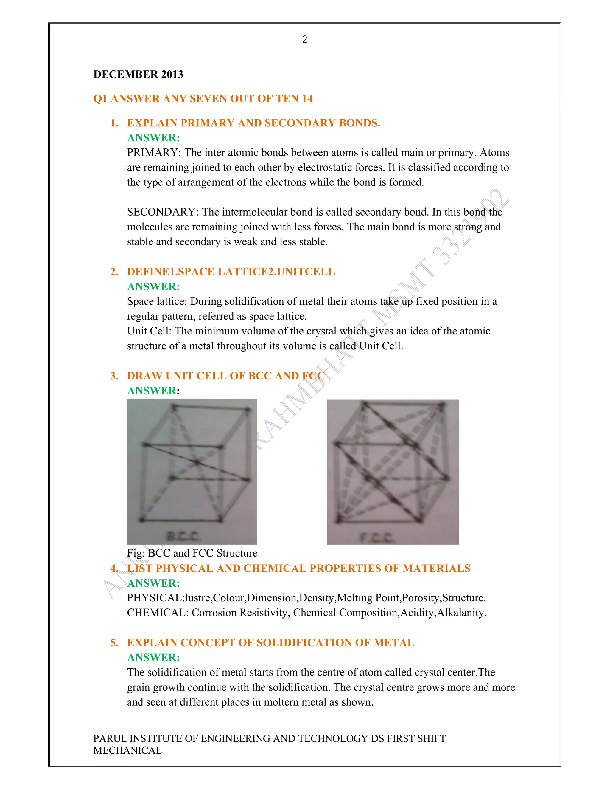
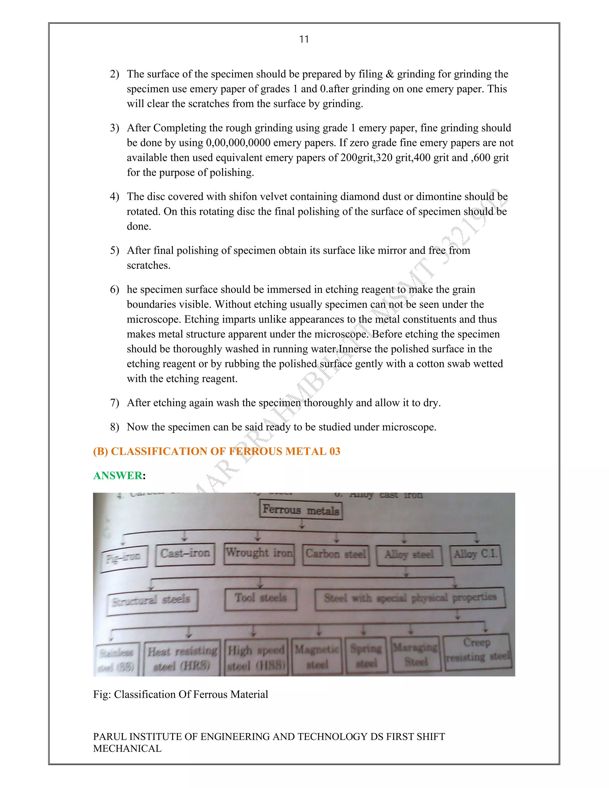
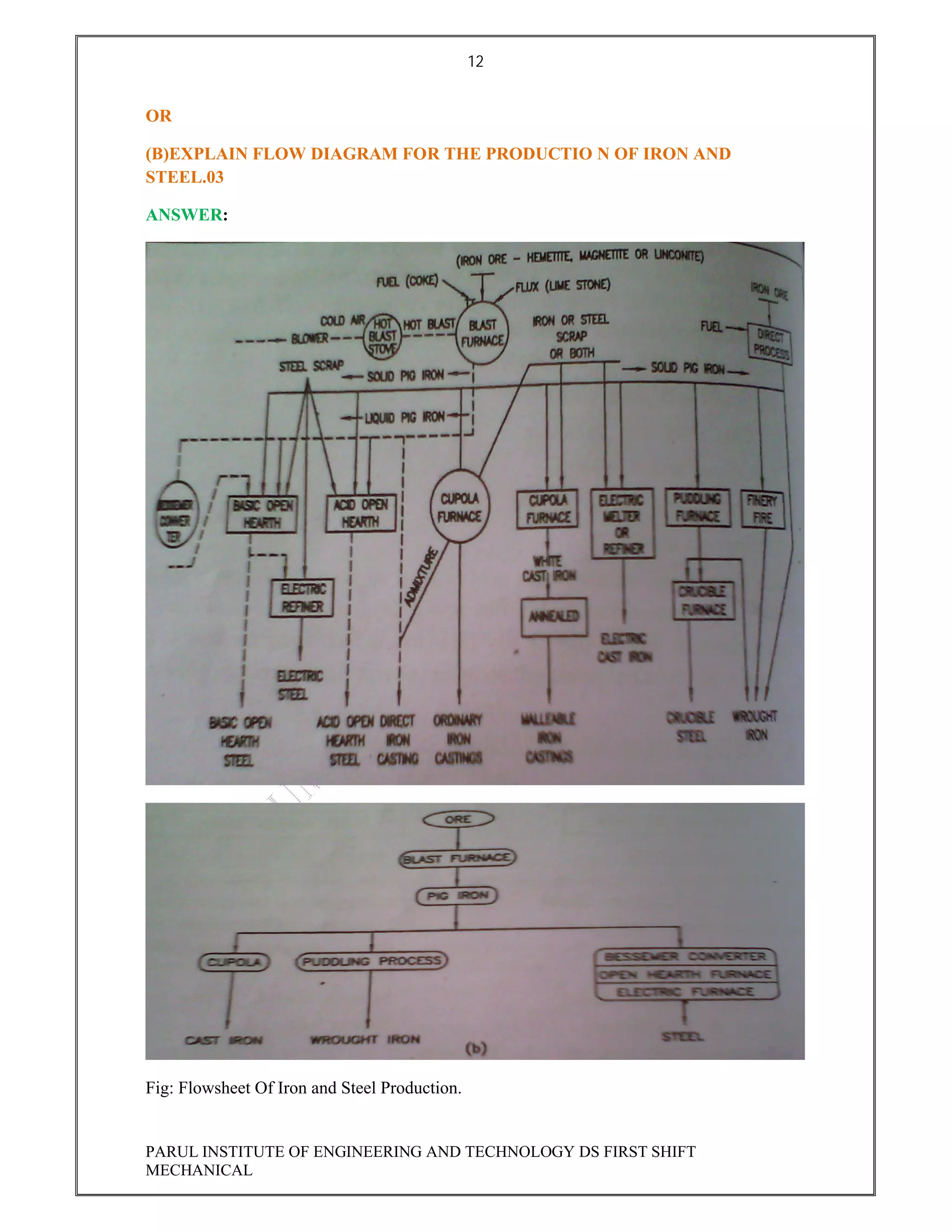
SlideShare a Scribd company logo
1 of 23
Download to read offline
1
1
GUJARAT TECHNOLOGICAL UNIVERSITY
MSMT DECEMBER 2013
SOLVED QUESTION PAPER
ANKITKUMAR BRAHMBHATT
12/20/2013
PARUL INSTITUTE OF ENGINEERING AND TECHNOLOGY DS FIRST
SHIFT(MECHANICAL)
2
PARUL INSTITUTE OF ENGINEERING AND TECHNOLOGY DS FIRST SHIFT
MECHANICAL
DECEMBER 2013
Q1 ANSWER ANY SEVEN OUT OF TEN 14
1. EXPLAIN PRIMARY AND SECONDARY BONDS.
ANSWER:
PRIMARY: The inter atomic bonds between atoms is called main or primary. Atoms
are remaining joined to each other by electrostatic forces. It is classified according to
the type of arrangement of the electrons while the bond is formed.
SECONDARY: The intermolecular bond is called secondary bond. In this bond the
molecules are remaining joined with less forces, The main bond is more strong and
stable and secondary is weak and less stable.
2. DEFINE1.SPACE LATTICE2.UNITCELL
ANSWER:
Space lattice: During solidification of metal their atoms take up fixed position in a
regular pattern, referred as space lattice.
Unit Cell: The minimum volume of the crystal which gives an idea of the atomic
structure of a metal throughout its volume is called Unit Cell.
3. DRAW UNIT CELL OF BCC AND FCC
ANSWER:
Fig: BCC and FCC Structure
4. LIST PHYSICAL AND CHEMICAL PROPERTIES OF MATERIALS
ANSWER:
PHYSICAL:lustre,Colour,Dimension,Density,Melting Point,Porosity,Structure.
CHEMICAL: Corrosion Resistivity, Chemical Composition,Acidity,Alkalanity.
5. EXPLAIN CONCEPT OF SOLIDIFICATION OF METAL
ANSWER:
The solidification of metal starts from the centre of atom called crystal center.The
grain growth continue with the solidification. The crystal centre grows more and more
and seen at different places in moltern metal as shown.
3
PARUL INSTITUTE OF ENGINEERING AND TECHNOLOGY DS FIRST SHIFT
MECHANICAL
Fig: Solidification Of Metal.
The regular shape crystal continue to develop with its growth. But with the free
growth of different crystals, their growth is restricted by one another giving alteration
of their shape.
This is seen occurring on the surface where crystal come in contact. The solidification
is complex process. Therefore it is difficult to obtain information of primary stage of
crystal centre formation.
Due to thermal motion of metal atoms its short range can not survive, however with
the decrease in temperature, micro volumes of short range go on increasing At
temperature lower than the temperature of solidification atom centre of solidifying
metal developes and become stable.
6. DEFINE 1.GRAIN 2.GRAIN BOUNDRY.
ANSWER:
GRAIN: The metal structure formed by the crystal is known as grain.
GRAIN BOUNDRY:Each grain starts from the nucleus so the crystallisation obtained is
dependent on the number of nucleus the orientation of the atoms arise from grain to grain.
The two hereby grain meet in a surface these surface is known as grain boundary.
7. WHAT IS EQUILIBRIUM DIAGRAM
ANSWER: The temperature composition diagram shows the changes of the structure taking
place during the heating and cooling is called as Equilibrium diagram.
On X AXIS: Metal Composition, Y AXIS :Temperature. It is also known as Phase Diagram
Fig: Equilibrium Diagram
When any Alloy after heating cooled down then changes taking place in it is shown
4
PARUL INSTITUTE OF ENGINEERING AND TECHNOLOGY DS FIRST SHIFT
MECHANICAL
by a curve known as Equilibrium Diagram or Phase Diagram or Constitutional
Diagram.
8. DEFINE SOLID SOLUTION AND GIVE EXAMPLES
ANSWER: In liquid stage metal form homogeneous liquid solution, The solid Solution is
formed. If Solvent &Solute atoms are of similar size and electron structure, solid solution
forms very readily if elements A in B forms solid solution in B by its 10%.
E.g Brass: Copper & Zinc,Steel:Iron & Carbon,Monel:Nickel&Copper,Au-Ag:Gold & Silver,
Sterling Silver: Silver & Copper.
9. WHAT IS COOLING CURVE AND DRAW COOLING CURVE OF METAL
& COMPOUND.
ANSWER:
Fig:Cooling Curve For Pure Metal
10. WRITE PROPERTIES OF SOLID SOLUTION.
ANSWER: : Properties
• Thermal &Electrical properties are reduced due to formation of solid solution.
• The strength and hardness of all the alloy metals increases due to solid solution
• Solid solution reduces the ductility &malleability of the alloys.
• The density, specific heat &heat distribution get changed according to the proportions
of alloying elements.
• By changing the proportion of the alloying element, there is no possibility to change
the stiffness any more.
• Solid solution alloys exhibit differential freezing.
• Solid solution are conductors but not as the pure metals on which they are based.
• The Constituents of the solid solution cannot be detected by the microscope.
• It is simply a solution in the solid state consisting of atoms combimned in one type of
space lattice.
5
PARUL INSTITUTE OF ENGINEERING AND TECHNOLOGY DS FIRST SHIFT
MECHANICAL
Q2 (A)STATE LEVER RULE AND EXPLAIN IT.03
ANSWER: On basis of phase Diagram No Of phase, and Composition Of phase can be
calculated .
Fig:Phase Diagram
lever rule is very important in two phase system to calculate the percentage of phase present
two lines are drawn and point is obtained which is between liquidus and solidus line G E H
Solid Phase Percentage=GE/GH*100 Liquid Phase Percentage=EH/GH*100
OR
(A)DRAW TTT DIAGRAM AND ITS APPLICATION
ANSWER:
Fig: TTT Equilibrium Diagram
The many heat treatment process of steel have reaction condition so far removed from
equilibrium hence iron carbon Eqm diagram is of only limited use for steels cools under non
Eqm condition.
6
PARUL INSTITUTE OF ENGINEERING AND TECHNOLOGY DS FIRST SHIFT
MECHANICAL
It shows only the phase and resulting microstructure corresponds to Eqm condition. Its
usefulness is to fix Austenizing temperature and predicting the phase obtained at given
temperature and percentage.
(B)DRAW NEAT SKETCH OF IRON CARBON DIAGRAM 09
ANSWER:
Fig: Iron Carbon Diagram.
OR
(B) LIST AT LEAST SIX INFORMATION FROM AN EQUILIBRIUM DIAGRAM
ANSWER:
• System: Part of the substance which is completely separated from the surrounding.
• Component: Basic chemical substance, whose mass is constant and which can be
used to form a chemical mixture.
• Phase: The part of material system uniformly mixed physically.
• Constituent:The part of multiphase mixture which can be identified separately.
• Liquidus:The locus of temperature at which solidification is complete. below solidus
only solids are stable.
7
PARUL INSTITUTE OF ENGINEERING AND TECHNOLOGY DS FIRST SHIFT
MECHANICAL
• Solidus:The locus of temperature of a transformation at which solidification starts.
• Solvent: The major element of a sold solution.
• Solute: The minor element of a solid solution.
• When an alloy after heating ,cooled down then the changes taking place in it is shown
by a curve known as “Equilibrium Diagram” known as Phase Diagram. It is graphical
description of the alloy system.
• The system shows the Melting points and Freezing points of all its alloy.
• Temperature, Pressure of Element& Proportion of the constituent are the major
factors in this equilibrium diagram with the help of variation the equilibrium diagram
is constructed.
(C)WHAT IS HEAT TREATMENT PROCESS?LIST TYPES OF FURNACES. 04
ANSWER: The Entire heat treatment process depends upon following three important
principle
a. Phase transformation during heating
b. Structural changes during cooling due to different cooling rates.
c. Effect of carbon content and other alloying elements.
Definition of Heat treatment Process
• It is sequential process of heating and cooling the steel component to get desired
combination of properties in the component.
Fig: Basic Of Heat Treatment
• Heating Component at higher temperature called austenitizing temperature, during
which the previous structure of steel is converted in to Austenite phase.
• Holding the steel at austenitizing temperature for some time period so that formation
of homogenous austenite can occur throughout the entire cross section of the part.
TEMP
TIME
ROOM TEMP
8
PARUL INSTITUTE OF ENGINEERING AND TECHNOLOGY DS FIRST SHIFT
MECHANICAL
• Cooling back the part which is having homogenous austenitic structure to the room
temperature at a particular cooling rate depending upon the properties required.
• Reheating of component to a higher temperature but lower than lower critical
temperature and cooling again this is an optional process and performed if required.
OR
(C)EXPLAIN ANNEALING PROCESS. 04
ANSWER: Annealing
• Heating the steel to austenite phase and then cooling slowly through the
transformation range. Slow cooling is generally achieved in a closed furnace by
switching off the supply to the furnace.
Fig:Types Of Anneling
Purpose Of Annealing:
• To produce the desired microstructure having mechanical.physical,and other
properties as per the requirement.
• To reduce hardness and soften the steel
• To relieve the internal stress.
• To restore the ductility and thereby facilitate further cold working
• To improve Machinability.
• To refine and make homogeneous structure by reducing structural in homogeneities
• To create complete stable structure.
• Increase or restore toughness.
9
PARUL INSTITUTE OF ENGINEERING AND TECHNOLOGY DS FIRST SHIFT
MECHANICAL
(D)EXPLAIN INDUCTION HARDENING. 04
ANSWER: Induction Hardening
• Parts are heated by induction heating.
• High frequency induction current is used.
• Required current is produced by using motor generator set with spark gas oscillator or
tube oscillator.
• Frequency of 1000-1000C/s.
Fig: Induction Hardening Process
• The gap oscillator can generate the current having frequency of 100000 to 400000
C/s.
• When Current of required frequency is passed through induction coil, magnetic lines
will pass through the part surface, due to that AC current will induce in the surface
which cause hysteresis loss in it and as a result of that parts get heated.
• The induced current travels along the surface of the part. For Quenching ,water is
sprinkled on the parts through the voids of inductor block & coil.
• This contain 0.35-0.55%c can be done. The induction hardening process is used for
the parts like camshafts,Gears,Cranckshaft,axles,and other automobile parts and
tractor parts.
OR
(D)WRITE SHORT NOTE ON FLAME HARDENING
ANSWER: Flame Hardening:
• This process is used for hardening stell,dye,gears,tappet screw,rocker arms and
valves. This is the process of obtaining wear resistant layer on the tough core by
heating the parts using gas torch.
• This process is utilized for the parts containing 0.4 % to 0.6% C.The surface is heated
by the oxy acetylene flame. By heating for sufficient time the temperature of the part
10
PARUL INSTITUTE OF ENGINEERING AND TECHNOLOGY DS FIRST SHIFT
MECHANICAL
is raised above AC3 temperature and thereafter fast quenching is done. The surfaces
of large size parts can be hardened is an advantage of this process.
Fig: Flame Hardening
• Heating cycle is less,which cause scaling. A fixed temperature can not be maintained
is the disadvantage of this process.
• The parts are also damaged due to overheating or cracks are formed in it.
Q3 (A) DRAW LINE DIAGRAM OF METALLURGICAL MICROSCOPE.03
ANSWER:
Fig: line Diagram Of Metallurgical Microscope
OR(A)STATE THE STEPS OF PREPARING A MICRO SPECIMEN I N SEQUENCE.
ANSWER:
1) To examine the internal details % structure of the metal specimen of 1cm,size should
be prepared.
11
PARUL INSTITUTE OF ENGINEERING AND TECHNOLOGY DS FIRST SHIFT
MECHANICAL
2) The surface of the specimen should be prepared by filing & grinding for grinding the
specimen use emery paper of grades 1 and 0.after grinding on one emery paper. This
will clear the scratches from the surface by grinding.
3) After Completing the rough grinding using grade 1 emery paper, fine grinding should
be done by using 0,00,000,0000 emery papers. If zero grade fine emery papers are not
available then used equivalent emery papers of 200grit,320 grit,400 grit and ,600 grit
for the purpose of polishing.
4) The disc covered with shifon velvet containing diamond dust or dimontine should be
rotated. On this rotating disc the final polishing of the surface of specimen should be
done.
5) After final polishing of specimen obtain its surface like mirror and free from
scratches.
6) he specimen surface should be immersed in etching reagent to make the grain
boundaries visible. Without etching usually specimen can not be seen under the
microscope. Etching imparts unlike appearances to the metal constituents and thus
makes metal structure apparent under the microscope. Before etching the specimen
should be thoroughly washed in running water.Innerse the polished surface in the
etching reagent or by rubbing the polished surface gently with a cotton swab wetted
with the etching reagent.
7) After etching again wash the specimen thoroughly and allow it to dry.
8) Now the specimen can be said ready to be studied under microscope.
(B) CLASSIFICATION OF FERROUS METAL 03
ANSWER:
Fig: Classification Of Ferrous Material
12
PARUL INSTITUTE OF ENGINEERING AND TECHNOLOGY DS FIRST SHIFT
MECHANICAL
OR
(B)EXPLAIN FLOW DIAGRAM FOR THE PRODUCTIO N OF IRON AND
STEEL.03
ANSWER:
Fig: Flowsheet Of Iron and Steel Production.
13
PARUL INSTITUTE OF ENGINEERING AND TECHNOLOGY DS FIRST SHIFT
MECHANICAL
(C)STATE PROPERTIES AND USE OF MALLEABLE CAST IRON. 04
ANSWER:
Table: Properties and Use of MCI
OR
Properties Uses
Its Yield Strength is more In rail road
Its core of thermal expansion is
less.
In agricultural tools.
Wear resistance In hardware of electric lines.
Absorbs Vibrations In chain links of conveyors.
It is cheap To manufacture gear case
It is tough metal In yoke of universal joints.
It can be Heat treated To improve differential housings
Its ductility is good In automobile cranck shafts.
Have good Machining
Properties, Hence It can be
Machined Very Easily.
To improve crankshaft sockets
To manufacture the hub of the wagon
wheels.
To manufacture hinges and locks.
14
PARUL INSTITUTE OF ENGINEERING AND TECHNOLOGY DS FIRST SHIFT
MECHANICAL
(C)DEFINE ALLOY STEEL.STATE THE REASON OF ALLOYING STEEL. 04
ANSWER:
By adding in plain carbon steel,the elements like
nickel,Chromium,Mangenese,Cobalt,Tungsten,Vanadium,Silicon,Aluminium,the steel
produced is known as Alloy Steel.By adding these elements the properties of plain carbon
steel increses.
The main constituents of plain carbon steel are iron& carbon.The properties of carbon steels
are directly related to the percentage of carbon present.The presence of other elements such
as Mn,Si,S,P do not have an appriciable effect on the properties of carbon steel.Alloy steel is
the steel to which elements other than carbon are added in sufficient amount to produce
improvement in properties.
The common added elements include Ni,Co,Cu,Al,and B.Each element confers certain
quality upon the steel to which it is added.They may be used seperately or in combination to
produce desired properties in steel.The compositional and structural changes produced by
alloying elements changes and improves the physical,Mechanical,properties of the iron and
steel.In general alloy steel can provide better strength,Ductility & Toughness,That can not be
obtained in PCS.
Reasons:
1) The alloying elements by mixing in solid solution improves the strength of the steel.
2) They increase the hardness.
3) Increases the high heat capacity.
4) Increases the depth of hardness.
5) The fatigue and creep resistance increases.
6) The machinability is improved.
7) It increases the weld ability.
8) Improves Magnetic Properties.
9) Improves Castability.
10) Obtains heat resistance properties.
11) Refines the Grain and microstructure.
12) Promotes Graphite Formation.
13) Increases the rate of cutting.
14) Increases or Decreases the critical points to stabilise the austenite.
15
PARUL INSTITUTE OF ENGINEERING AND TECHNOLOGY DS FIRST SHIFT
MECHANICAL
(D)STATE THE APPLICATION AND PROPERTIES OF GCI. 04
ANSWER:
Table: Application and Properties Of GCI
OR
(D)GIVE DESIGNATION OF STEEL (A)C15(B)T90(C)80 T 11(D)25 Cr 4 Mo 2G 04
ANSWER:
C 15 Carbon steel containing ,Avg 0.15% Carbon.
T 90 Unalloyed Tool Steel T=Tool,90=Carbon Content 0.9%
80 T 11: 80Carbon 0.8%,T =Tool Steel,11 Sulphur 0.11%
Properties Uses
Its Yield Strength is more In rail road
Its core of thermal expansion is
less.
In agricultural tools.
Wear resistance In hardware of electric lines.
Absorbs Vibrations In chain links of conveyors.
It is cheap To manufacture gear case
It is tough metal In yoke of universal joints.
It can be Heat treated To improve differential housings
Its ductility is good In automobile cranck shafts.
Have good Machining
Properties, Hence It can be
Machined Very Easily.
To improve crankshaft sockets
To manufacture the hub of the wagon wheels.
To manufacture hinges and locks.
16
PARUL INSTITUTE OF ENGINEERING AND TECHNOLOGY DS FIRST SHIFT
MECHANICAL
25 Cr 4 Mo 2 G 04: Carbon content 0.25%,Cr 4 Chromium Content 4%,Mo 2 Molybdenum
Content 0.2%,G hardenability of this steel is guaranteed.
Q4 (A)WRITE PROPERTIES OF COPPER. 03
ANSWER:
1) It is having Shining Yellowish red colour.
2) It is anti corrosive metal.
3) Density is 8.9 gm/cm3.
4) It is Good Conductor of Heat and Electricity.
5) Melting point is 1083°C.
6) It is having FCC Crystal Structure.
7) Machinability is very good.
8) It can be easily welded.
9) It is easy to cast.
10) It can be hot and cold worked.
11) Tensile strength 180-200 N/mm2
12) Hardness is 30-40 B.H.N
13) If annealed we can get elongation up to 50-60%.
OR
(A)STATE APPLICATION OF ALLUMINIUM IN ENGINEERING STATING
REASON FOR ITS SELECTION.03
ANSWER:
1) Good Corrosion Resistance: Marine application, Window corner casting, Water jug
manufacturing.
2) Castablity,Chemical Resistance,Machining and Welding Properties:Air and Water
Cooled Cylinder Block Manufacturing.
3) Good Mechanical Properties, Best Corrosion Resistance, Good Machinability:
Aircraft casting, Marine Fittings, Mining Equipments.
4) Low Heat Expansion Rate: Internal Combustion Engine Piston Manufacturing.
17
PARUL INSTITUTE OF ENGINEERING AND TECHNOLOGY DS FIRST SHIFT
MECHANICAL
5) Good Castability
(B)WHICH REQUIREMENT OF BEARING METAL CAN MINIMIZE THE
FAILURE?04
ANSWER:
1) By using the metal having good compressive strength at working temperature.
2) Can protect oil film on bearing surface.
3) Low coefficient of friction with shaft.
4) Having good thermal conductivity for the heat which is generated due to friction
between bearing and shaft.
5) Corrosion resistant.
6) Having good plasticity under the action of bearing load which can distribute uniform
load.
7) Anti seizure properties.
8) Vibration and Shock resistance.
9) long service life.
10) Bearing material should be soft than the shaft material so that no friction between
bearing and shaft.
OR
(B)CLASSIFICATION OF INSULATING MATERIALS AND STATE THEIR
PROPERTIES. 04
ANSWER:
HEAT RESISTANT: Asbestos, Glass wool,Gasket,Thermocole,Polyurethroform(PUF),Cork.
Insulating
Materials
Heat
Resistant
Electrical Resistant
18
PARUL INSTITUTE OF ENGINEERING AND TECHNOLOGY DS FIRST SHIFT
MECHANICAL
ELECTRICAL RESISTANT:Glass,Mica,Ceramic,Asbestos,Resin,Rubber.
HEAT AND ELECTRICAL INSULATING PROPERTIES:
HEAT: It is capable of enduring high temperatures, Capable of preventing Heat Loss,
Tensile strength is more, Resistance to acid and fumes, It is resistance to mosture,Shock
resistance properties is good.
ELECTRICAL: Higher Dielectric Strength, It is not a moisture absorbing material, There is
no change in the shape at higher temperatures,cheaper,Specific resistance is more, Stable
against chemical attack, Mechanical strength is more.
Properties
Asbestos: Colour are grey, white and brown, Resistant to Acid and Base, Resistant to Heat,
Sound, and Electricity, Die electric and material strength are good.
Glass wool: Material is good heat resistant, Less effect of chemical, Tensile strength is more,
Can bare high temperatures.
Polyurethroform(PUF):It is used an alternative to the glass wool. It is considered as compact
and high thermal insulator, Used in refrigerator wall .
Gasket: It can endure high temperature,Nioprene cement can be used up to temperatures of
200°c,Cu gasket used in automobile.
Glass: Inorganic resistant material, Main Constituent is silica, It has best insulating
properties, It has good die electric strength.
Mica: It is crystalline material having HCP, It can be device in to thin layers, Good Die
electric and Mechanical Strength.
Ceramic: Its dielectric constant is in the range of 4 to10,More Die electric and Mechanical
Strength, It Can Endure High Temperatures, It can be Moulded in any Shape and Size.
(C) LIST THE CERAMIC MATERIALS AND STATE THE CHARACTERISTICS
OF CERAMIC MATERIALS WHICH MAKE IT USEFUL AS AN ENGINEERING
MATERIAL. 07
ANSWER:
The ceramic are classified according to their industrial application and structure in two
groups as under
(A).Classification as per use.
1.Alumina,Silica,Carborandum.
2.Bricks,Tiles,Porcelain etc fire clay products.
19
PARUL INSTITUTE OF ENGINEERING AND TECHNOLOGY DS FIRST SHIFT
MECHANICAL
3.Pure Oxide Ceramic like Mg,Si,Al,Cr Oxides.
4.Glass Material like Coloured glass, Window Glass.
5.Rocks like granite, sand stone,magnetite,.silinite.chromite.
6.Minerals like Quartz,Selspar,Calcite.
7.Refractory materials like acidic.Basic.Neutral refractoriness.
(B).Classification as per its composition.
1.Crystalline ceramic like magnesite,Alumina.
2.Non Crystalline Ceramics like natural &Synthetic Glass,
3.Bonded Ceramic Like Fire clay.
4.Amorphous and Crystalline wood.
5.Crystalline and Non Crystalline Cements.
Characteristics Of Ceramic :
1) It is having good compressive strength so used to carry compressive load of Brick,
Cement.
2) Very Good Shear Strength and fracture strength is poor hence brittle failures of
ceramic occurs.
3) Tensile strength of ceramic is less, but glass fibres has 700MN/m2.
4) Bond strength is very high.
5) Ceramic like Clay & other layers deform plastically.
6) Electrical resistance of ceramic is high.
7) Spinal Structure of ceramic are magnetic material.
8) The specific heat of clay brick is 0.25 at 1000°C.
9) Its heat conductivity is poor due to its lesser density.
10) ceramics are generally opaque or non opaque.
11) It remain stable at high temperatures and retains its shape.
12) It is hard,strong,dense endure more forces.
20
PARUL INSTITUTE OF ENGINEERING AND TECHNOLOGY DS FIRST SHIFT
MECHANICAL
Q5 (A)TYPES OF CORROSION AND EXPLAIN ANY ONE CORROSION. 04
ANSWER:
Types of Corrosion
1) Uniform
2) Pitting
3) Stress Corrosion
4) Biological
5) High temperature
6) Galvenic
7) Selective Corrosion
8) Erosion Corrosion
9) Intergrated Corrosion
10) Crevice Corrosion
11) Surface Corrosion
12) Fretting Corrosion.
Uniform: This type of corrosion initially occur on some portion of the surface and then
spread on the whole surface. Continuous reduction in metal volume is caused by this
corrosion. As this type of corrosion occurs equally on whole surface hence it is called
"Uniform Corrosion".
If the parts are not produced from the corrosion resistant material, then strength of them are
reduces due to this corrosion. The ways of preventing it are change of material and coating
the surface with corrosion resisting material. This type of corrosion results into grater loss
hence parts are to be produced using corrosion resistant material.
(B)STATE APPLICATION AND LIMITATION OF POWDER METALLURGY 04
ANSWER:
Limitation
• Excessive pure powder of best quality is difficult to produce without which
component of good physical properties cannot be produced. Again to obtain such
powder are expensive.
21
PARUL INSTITUTE OF ENGINEERING AND TECHNOLOGY DS FIRST SHIFT
MECHANICAL
• The die,punch,press and sintering furnace are very costly equipments, hence powder
metallurgy proves expensive for producing parts in small number.
• In absence of simple methods to produce powder of steel,brass,bronze etc is difficult.
• The parts produced by powder metallurgy cannot be used for many application due to
its impact strength,ductility,and elongation are less.
• Large component in comparison to casting cannot be produced due to the
requirement of large press &expensive tools.
• High attention is required while preparing powders of highly combustible materials
like magnesium,thorium,zirconium,and toxic material like barium,uranium,and
thorium.
• The parts pressed from the top are less dense at the bottom.
• Many metals are cold welded with die materials which increases the wear of the die.
So difficult to press or compact using the die and press.
Application
• To produce refractory parts of tungsten,Tantalum,Molybdenum which are used in the
electrical bulb, radio valves ray tube filaments,cathod,anode and control grids e.g.
WC.
• To produce refractory carbide, which are difficult to machine e.g. WC
• Automobile applications, electrical contracts,Cranckshaft drive, camshaft sprockets,
piston rings, brake lining by PM root.
• To produce self lubricating bearings and filters.
• To produce intricate gears which needs more machining if produced by conventional
method.
• Components of two metals and non metals like non porous bearings, electric motor
brush are produced by powder metallurgy.
• Aerospace application:rocket,missile,satellite,space vehicle parts,e.g Be,Al,Zr
powders are used in Solid fuel rocket.
• Atomic Energy application are Be as fuel canning material, powder control
rod,Rediation reflector,Zr and alloy as cladding material.
• Grinding Wheels containing steel & diamond powders are produced by powder
metallurgy.
• Various parts of watches, type writter.calculator,Clutch&brake by P/M root.
22
PARUL INSTITUTE OF ENGINEERING AND TECHNOLOGY DS FIRST SHIFT
MECHANICAL
(C)EXPLAIN SURFACE COATING THROUGH ELECTROLYSIS SETUP. 03
ANSWER:
• For Electroplating electrolysis cell is used. The metal to be protected is made cathode.
The metal to be coated is made anode.
• Salt water of anode metal is taken as electrolyte. Using rectifier the electricity supply
is given Anode to Cathode.
• Decomposition of electrolyte takes place and metal gets deposited on the Cathode by
this way surface protective coating is done. Slowly anode gets dissolved in electrolyte
and maintain anode metal composition, by this way desired thickness of coating is
done.
• The metal which can be coated are Cu,Cr,Ni,Zn,Cd,Sn,Pb,Ag,Au.Using this 1.25
micron coating is done for decorative purposes.
Fig: Electrolytic Coating Process
(D)ENLIST SIX PROPERTIES OF OIL AND EXPLAIN ANY ONE IN DETAIL. 03
ANSWER: Properties of the oil
1) Viscosity
2) Viscosity Index
3) Cloud Point and Pour Point
4) Flash Point
5) Specific Gravity
6) Carbon Residue
7) Oiliness
8) Oxidation Stability
23
PARUL INSTITUTE OF ENGINEERING AND TECHNOLOGY DS FIRST SHIFT
MECHANICAL
9) Cleanliness
10) Colour
11) Acidity & Neutralisation Number.
Cloud Point And Pour Point: When oil is cooled at some temperature it converts to Solid
form this locus of temperature is called as cloud point. Cloud Point is creating resistance to
flow the oil.
Pour point the locus of temperature above which the oil will not flow.The pour point of the
oil is showing its ability to move at low temperature .This property is considered as it has its
effect on starting engine in cold weather and circulation of oil through pipes when pressure is
not applied.For to obtain maximum circulation the pour point should be low by at least 15°F
in comparision to the engine operating temperatures.
BEST OF LUCK

More Related Content

What's hot

Heat treatment processes
Heat treatment processesHeat treatment processes
Heat treatment processesSaiGayathri12
 
Heat treatment lecture note
Heat treatment lecture note Heat treatment lecture note
Heat treatment lecture note Salem Karrab
 
Heat treatment part 1
Heat treatment part 1Heat treatment part 1
Heat treatment part 1Naman Dave
 
Heat treatment process(TTT, CCT &CCR)
Heat treatment process(TTT, CCT &CCR)Heat treatment process(TTT, CCT &CCR)
Heat treatment process(TTT, CCT &CCR)KISHOR GHEGAD
 
Iron iron carbide diagram By Hariprasad
Iron iron carbide diagram By HariprasadIron iron carbide diagram By Hariprasad
Iron iron carbide diagram By HariprasadSachin Hariprasad
 
Phase transformation physical metallurgy
Phase transformation physical metallurgyPhase transformation physical metallurgy
Phase transformation physical metallurgyDeepak Patel
 
Iron – carbon phase diagram
Iron – carbon phase diagramIron – carbon phase diagram
Iron – carbon phase diagramEng.Ahmed Samy
 
Iron Carbon diagram
Iron Carbon diagramIron Carbon diagram
Iron Carbon diagramNaman Dave
 
Ttt diagram for eutectoid steel(bainite, spherodite, martensite)
Ttt diagram for eutectoid steel(bainite, spherodite, martensite)Ttt diagram for eutectoid steel(bainite, spherodite, martensite)
Ttt diagram for eutectoid steel(bainite, spherodite, martensite)darshit1671998
 
6 heat treatment-of_steel
6 heat treatment-of_steel6 heat treatment-of_steel
6 heat treatment-of_steelMukhlis Adam
 
Conventional heat treatment of low carbon steel
Conventional heat treatment of low carbon steelConventional heat treatment of low carbon steel
Conventional heat treatment of low carbon steelAyush Chaurasia
 
Ch04
Ch04Ch04
Ch04klivsie
 
Time temperature transformation curves 2
Time temperature transformation curves 2Time temperature transformation curves 2
Time temperature transformation curves 2onlinemetallurgy.com
 
Phase transformation (Material Science)
Phase transformation (Material Science)Phase transformation (Material Science)
Phase transformation (Material Science)Myo Zin Aung
 

What's hot (19)

Heat treatment processes
Heat treatment processesHeat treatment processes
Heat treatment processes
 
Heat treatment lecture note
Heat treatment lecture note Heat treatment lecture note
Heat treatment lecture note
 
Heat treatment part 1
Heat treatment part 1Heat treatment part 1
Heat treatment part 1
 
Annealing presentation
Annealing presentationAnnealing presentation
Annealing presentation
 
Heat treatment process(TTT, CCT &CCR)
Heat treatment process(TTT, CCT &CCR)Heat treatment process(TTT, CCT &CCR)
Heat treatment process(TTT, CCT &CCR)
 
Iron iron carbide diagram By Hariprasad
Iron iron carbide diagram By HariprasadIron iron carbide diagram By Hariprasad
Iron iron carbide diagram By Hariprasad
 
L 08
L 08L 08
L 08
 
02 heat treatment
02 heat treatment02 heat treatment
02 heat treatment
 
Phase transformation physical metallurgy
Phase transformation physical metallurgyPhase transformation physical metallurgy
Phase transformation physical metallurgy
 
Iron – carbon phase diagram
Iron – carbon phase diagramIron – carbon phase diagram
Iron – carbon phase diagram
 
Iron Carbon diagram
Iron Carbon diagramIron Carbon diagram
Iron Carbon diagram
 
L 06
L 06L 06
L 06
 
Ttt diagram for eutectoid steel(bainite, spherodite, martensite)
Ttt diagram for eutectoid steel(bainite, spherodite, martensite)Ttt diagram for eutectoid steel(bainite, spherodite, martensite)
Ttt diagram for eutectoid steel(bainite, spherodite, martensite)
 
6 heat treatment-of_steel
6 heat treatment-of_steel6 heat treatment-of_steel
6 heat treatment-of_steel
 
H0351046052
H0351046052H0351046052
H0351046052
 
Conventional heat treatment of low carbon steel
Conventional heat treatment of low carbon steelConventional heat treatment of low carbon steel
Conventional heat treatment of low carbon steel
 
Ch04
Ch04Ch04
Ch04
 
Time temperature transformation curves 2
Time temperature transformation curves 2Time temperature transformation curves 2
Time temperature transformation curves 2
 
Phase transformation (Material Science)
Phase transformation (Material Science)Phase transformation (Material Science)
Phase transformation (Material Science)
 

Viewers also liked

GTU MSMT UNIT 2 STUDY MATERIAL
GTU MSMT UNIT 2 STUDY MATERIALGTU MSMT UNIT 2 STUDY MATERIAL
GTU MSMT UNIT 2 STUDY MATERIALANKIT BRAHMBHATT
 
Pressure Measurement
Pressure MeasurementPressure Measurement
Pressure MeasurementApoorv00
 
10 toxic people you should avoid at all costs
10 toxic people you should avoid at all costs10 toxic people you should avoid at all costs
10 toxic people you should avoid at all costsANKIT BRAHMBHATT
 
KINEMATICS OF MACHINES
KINEMATICS OF MACHINESKINEMATICS OF MACHINES
KINEMATICS OF MACHINESUmang Parmar
 
Measurement of liq pressure
Measurement of liq pressureMeasurement of liq pressure
Measurement of liq pressureapb2179
 
Chapter 1 material structure and binary alloy system
Chapter 1   material structure and binary alloy systemChapter 1   material structure and binary alloy system
Chapter 1 material structure and binary alloy systemsakura rena
 
Vacuum gauge and valves
Vacuum gauge and valvesVacuum gauge and valves
Vacuum gauge and valvesmahakalvar
 
Branches of TOM, Machine & Structure, Kinematic Links
Branches of TOM, Machine & Structure, Kinematic LinksBranches of TOM, Machine & Structure, Kinematic Links
Branches of TOM, Machine & Structure, Kinematic LinksAkash Patel
 
Final instrumentation lab manual
Final instrumentation lab manualFinal instrumentation lab manual
Final instrumentation lab manualkishorereddy_btech
 
fluid-mechanics
fluid-mechanicsfluid-mechanics
fluid-mechanicsElias T Maida
 
“V - Belts” - Design of Machine Element
“V - Belts” - Design of Machine Element “V - Belts” - Design of Machine Element
“V - Belts” - Design of Machine Element Umang Parmar
 
Material technology
Material technologyMaterial technology
Material technologyPrem Baboo
 
Pressure measurement
Pressure measurement Pressure measurement
Pressure measurement Uttam Trasadiya
 
Thermocouple gauge & pirani gauge
Thermocouple gauge & pirani gauge  Thermocouple gauge & pirani gauge
Thermocouple gauge & pirani gauge Naveen Choudhary
 
Solid solution strengthening
Solid solution strengtheningSolid solution strengthening
Solid solution strengtheningJAYESH PAREKH
 

Viewers also liked (20)

GTU MSMT UNIT 2 STUDY MATERIAL
GTU MSMT UNIT 2 STUDY MATERIALGTU MSMT UNIT 2 STUDY MATERIAL
GTU MSMT UNIT 2 STUDY MATERIAL
 
Quotes sir mv
Quotes sir mvQuotes sir mv
Quotes sir mv
 
Pressure Measurement
Pressure MeasurementPressure Measurement
Pressure Measurement
 
Solved paper msmt 2
Solved paper msmt 2Solved paper msmt 2
Solved paper msmt 2
 
10 toxic people you should avoid at all costs
10 toxic people you should avoid at all costs10 toxic people you should avoid at all costs
10 toxic people you should avoid at all costs
 
KINEMATICS OF MACHINES
KINEMATICS OF MACHINESKINEMATICS OF MACHINES
KINEMATICS OF MACHINES
 
Measurement of liq pressure
Measurement of liq pressureMeasurement of liq pressure
Measurement of liq pressure
 
Chapter 1 material structure and binary alloy system
Chapter 1   material structure and binary alloy systemChapter 1   material structure and binary alloy system
Chapter 1 material structure and binary alloy system
 
Vacuum gauge and valves
Vacuum gauge and valvesVacuum gauge and valves
Vacuum gauge and valves
 
Tom[unit 1]
Tom[unit 1]Tom[unit 1]
Tom[unit 1]
 
Branches of TOM, Machine & Structure, Kinematic Links
Branches of TOM, Machine & Structure, Kinematic LinksBranches of TOM, Machine & Structure, Kinematic Links
Branches of TOM, Machine & Structure, Kinematic Links
 
Final instrumentation lab manual
Final instrumentation lab manualFinal instrumentation lab manual
Final instrumentation lab manual
 
fluid-mechanics
fluid-mechanicsfluid-mechanics
fluid-mechanics
 
solid solutions
solid solutionssolid solutions
solid solutions
 
“V - Belts” - Design of Machine Element
“V - Belts” - Design of Machine Element “V - Belts” - Design of Machine Element
“V - Belts” - Design of Machine Element
 
Material technology
Material technologyMaterial technology
Material technology
 
Unit 23 - Fluid Pressure
Unit 23 - Fluid PressureUnit 23 - Fluid Pressure
Unit 23 - Fluid Pressure
 
Pressure measurement
Pressure measurement Pressure measurement
Pressure measurement
 
Thermocouple gauge & pirani gauge
Thermocouple gauge & pirani gauge  Thermocouple gauge & pirani gauge
Thermocouple gauge & pirani gauge
 
Solid solution strengthening
Solid solution strengtheningSolid solution strengthening
Solid solution strengthening
 

Similar to Final solved paper msmt 1

solidification and heat treatment.ppt
solidification and heat treatment.pptsolidification and heat treatment.ppt
solidification and heat treatment.pptSehranAmjad1
 
material science & engineering.ppt
material science & engineering.pptmaterial science & engineering.ppt
material science & engineering.pptAwadMElAraby1
 
Alloying Metals. Leaving Cert. Engineering.
Alloying Metals. Leaving Cert. Engineering.Alloying Metals. Leaving Cert. Engineering.
Alloying Metals. Leaving Cert. Engineering.fjpwhelan
 
CONSTITUTION OF ALLOYS
CONSTITUTION OF ALLOYSCONSTITUTION OF ALLOYS
CONSTITUTION OF ALLOYSMuthukumar V
 
UTILISATION OF ELECTRICAL ENERGY
UTILISATION OF ELECTRICAL ENERGY  UTILISATION OF ELECTRICAL ENERGY
UTILISATION OF ELECTRICAL ENERGY akbar ali
 
Heat treatment, phases, microstructures and its properties
Heat treatment, phases, microstructures and its propertiesHeat treatment, phases, microstructures and its properties
Heat treatment, phases, microstructures and its propertiesHitesh Basitti
 
1.2 resistance and special welding
1.2 resistance and special welding1.2 resistance and special welding
1.2 resistance and special weldingSuren Sirohi
 
Advanced metaullrgy final welding
Advanced metaullrgy final weldingAdvanced metaullrgy final welding
Advanced metaullrgy final weldingAhmed Awad
 
DJJ3213 MATERIAL SCIENCE CHAPTER 4 NOTE.ppt
DJJ3213 MATERIAL SCIENCE CHAPTER 4 NOTE.pptDJJ3213 MATERIAL SCIENCE CHAPTER 4 NOTE.ppt
DJJ3213 MATERIAL SCIENCE CHAPTER 4 NOTE.pptfieyzaadn
 
me6403_mm_unit_1_ppt.ppt
me6403_mm_unit_1_ppt.pptme6403_mm_unit_1_ppt.ppt
me6403_mm_unit_1_ppt.pptBavaM1
 
me6403_mm_unit_1_ppt.ppt
me6403_mm_unit_1_ppt.pptme6403_mm_unit_1_ppt.ppt
me6403_mm_unit_1_ppt.pptnandakumar469688
 
02_Heatflowinwelding and joining process
02_Heatflowinwelding and joining process02_Heatflowinwelding and joining process
02_Heatflowinwelding and joining processSakib987640
 
Reference for g vs r in sindo kou's book
Reference for g vs r in sindo kou's bookReference for g vs r in sindo kou's book
Reference for g vs r in sindo kou's bookVignesh Ganapathy
 
Material Bonding Powerpoint
Material Bonding PowerpointMaterial Bonding Powerpoint
Material Bonding PowerpointJutka Czirok
 
The Working principle of Thermocouple
The Working principle of ThermocoupleThe Working principle of Thermocouple
The Working principle of ThermocoupleManvik Joshi
 

Similar to Final solved paper msmt 1 (20)

solidification and heat treatment.ppt
solidification and heat treatment.pptsolidification and heat treatment.ppt
solidification and heat treatment.ppt
 
material science & engineering.ppt
material science & engineering.pptmaterial science & engineering.ppt
material science & engineering.ppt
 
Alloying Metals. Leaving Cert. Engineering.
Alloying Metals. Leaving Cert. Engineering.Alloying Metals. Leaving Cert. Engineering.
Alloying Metals. Leaving Cert. Engineering.
 
Welding metallurgy part i
Welding metallurgy part iWelding metallurgy part i
Welding metallurgy part i
 
CONSTITUTION OF ALLOYS
CONSTITUTION OF ALLOYSCONSTITUTION OF ALLOYS
CONSTITUTION OF ALLOYS
 
UTILISATION OF ELECTRICAL ENERGY
UTILISATION OF ELECTRICAL ENERGY  UTILISATION OF ELECTRICAL ENERGY
UTILISATION OF ELECTRICAL ENERGY
 
Unit 2 PPT.pptx
Unit 2 PPT.pptxUnit 2 PPT.pptx
Unit 2 PPT.pptx
 
Heat treatment, phases, microstructures and its properties
Heat treatment, phases, microstructures and its propertiesHeat treatment, phases, microstructures and its properties
Heat treatment, phases, microstructures and its properties
 
1.2 resistance and special welding
1.2 resistance and special welding1.2 resistance and special welding
1.2 resistance and special welding
 
Advanced metaullrgy final welding
Advanced metaullrgy final weldingAdvanced metaullrgy final welding
Advanced metaullrgy final welding
 
DJJ3213 MATERIAL SCIENCE CHAPTER 4 NOTE.ppt
DJJ3213 MATERIAL SCIENCE CHAPTER 4 NOTE.pptDJJ3213 MATERIAL SCIENCE CHAPTER 4 NOTE.ppt
DJJ3213 MATERIAL SCIENCE CHAPTER 4 NOTE.ppt
 
me6403_mm_unit_1_ppt.ppt
me6403_mm_unit_1_ppt.pptme6403_mm_unit_1_ppt.ppt
me6403_mm_unit_1_ppt.ppt
 
me6403_mm_unit_1_ppt.ppt
me6403_mm_unit_1_ppt.pptme6403_mm_unit_1_ppt.ppt
me6403_mm_unit_1_ppt.ppt
 
Heat treatment of Steels
Heat treatment of  SteelsHeat treatment of  Steels
Heat treatment of Steels
 
02_Heatflowinwelding and joining process
02_Heatflowinwelding and joining process02_Heatflowinwelding and joining process
02_Heatflowinwelding and joining process
 
6 heat treatment-of_steel
6 heat treatment-of_steel6 heat treatment-of_steel
6 heat treatment-of_steel
 
Reference for g vs r in sindo kou's book
Reference for g vs r in sindo kou's bookReference for g vs r in sindo kou's book
Reference for g vs r in sindo kou's book
 
Phase Transformation: Lecture Review of Phase Diagrams
Phase Transformation: Lecture Review of Phase Diagrams Phase Transformation: Lecture Review of Phase Diagrams
Phase Transformation: Lecture Review of Phase Diagrams
 
Material Bonding Powerpoint
Material Bonding PowerpointMaterial Bonding Powerpoint
Material Bonding Powerpoint
 
The Working principle of Thermocouple
The Working principle of ThermocoupleThe Working principle of Thermocouple
The Working principle of Thermocouple
 

Recently uploaded

Architect Hassan Khalil Portfolio for 2024
Architect Hassan Khalil Portfolio for 2024Architect Hassan Khalil Portfolio for 2024
Architect Hassan Khalil Portfolio for 2024hassan khalil
 
Application of Residue Theorem to evaluate real integrations.pptx
Application of Residue Theorem to evaluate real integrations.pptxApplication of Residue Theorem to evaluate real integrations.pptx
Application of Residue Theorem to evaluate real integrations.pptx959SahilShah
 
Oxy acetylene welding presentation note.
Oxy acetylene welding presentation note.Oxy acetylene welding presentation note.
Oxy acetylene welding presentation note.eptoze12
 
Microscopic Analysis of Ceramic Materials.pptx
Microscopic Analysis of Ceramic Materials.pptxMicroscopic Analysis of Ceramic Materials.pptx
Microscopic Analysis of Ceramic Materials.pptxpurnimasatapathy1234
 
Artificial-Intelligence-in-Electronics (K).pptx
Artificial-Intelligence-in-Electronics (K).pptxArtificial-Intelligence-in-Electronics (K).pptx
Artificial-Intelligence-in-Electronics (K).pptxbritheesh05
 
ZXCTN 5804 / ZTE PTN / ZTE POTN / ZTE 5804 PTN / ZTE POTN 5804 ( 100/200 GE Z...
ZXCTN 5804 / ZTE PTN / ZTE POTN / ZTE 5804 PTN / ZTE POTN 5804 ( 100/200 GE Z...ZXCTN 5804 / ZTE PTN / ZTE POTN / ZTE 5804 PTN / ZTE POTN 5804 ( 100/200 GE Z...
ZXCTN 5804 / ZTE PTN / ZTE POTN / ZTE 5804 PTN / ZTE POTN 5804 ( 100/200 GE Z...ZTE
 
Internship report on mechanical engineering
Internship report on mechanical engineeringInternship report on mechanical engineering
Internship report on mechanical engineeringmalavadedarshan25
 
(MEERA) Dapodi Call Girls Just Call 7001035870 [ Cash on Delivery ] Pune Escorts
(MEERA) Dapodi Call Girls Just Call 7001035870 [ Cash on Delivery ] Pune Escorts(MEERA) Dapodi Call Girls Just Call 7001035870 [ Cash on Delivery ] Pune Escorts
(MEERA) Dapodi Call Girls Just Call 7001035870 [ Cash on Delivery ] Pune Escortsranjana rawat
 
main PPT.pptx of girls hostel security using rfid
main PPT.pptx of girls hostel security using rfidmain PPT.pptx of girls hostel security using rfid
main PPT.pptx of girls hostel security using rfidNikhilNagaraju
 
Introduction to Microprocesso programming and interfacing.pptx
Introduction to Microprocesso programming and interfacing.pptxIntroduction to Microprocesso programming and interfacing.pptx
Introduction to Microprocesso programming and interfacing.pptxvipinkmenon1
 
Past, Present and Future of Generative AI
Past, Present and Future of Generative AIPast, Present and Future of Generative AI
Past, Present and Future of Generative AIabhishek36461
 
HARMONY IN THE NATURE AND EXISTENCE - Unit-IV
HARMONY IN THE NATURE AND EXISTENCE - Unit-IVHARMONY IN THE NATURE AND EXISTENCE - Unit-IV
HARMONY IN THE NATURE AND EXISTENCE - Unit-IVRajaP95
 
IVE Industry Focused Event - Defence Sector 2024
IVE Industry Focused Event - Defence Sector 2024IVE Industry Focused Event - Defence Sector 2024
IVE Industry Focused Event - Defence Sector 2024Mark Billinghurst
 
VIP Call Girls Service Hitech City Hyderabad Call +91-8250192130
VIP Call Girls Service Hitech City Hyderabad Call +91-8250192130VIP Call Girls Service Hitech City Hyderabad Call +91-8250192130
VIP Call Girls Service Hitech City Hyderabad Call +91-8250192130Suhani Kapoor
 
Gfe Mayur Vihar Call Girls Service WhatsApp -> 9999965857 Available 24x7 ^ De...
Gfe Mayur Vihar Call Girls Service WhatsApp -> 9999965857 Available 24x7 ^ De...Gfe Mayur Vihar Call Girls Service WhatsApp -> 9999965857 Available 24x7 ^ De...
Gfe Mayur Vihar Call Girls Service WhatsApp -> 9999965857 Available 24x7 ^ De...srsj9000
 
microprocessor 8085 and its interfacing
microprocessor 8085  and its interfacingmicroprocessor 8085  and its interfacing
microprocessor 8085 and its interfacingjaychoudhary37
 
High Profile Call Girls Nagpur Isha Call 7001035870 Meet With Nagpur Escorts
High Profile Call Girls Nagpur Isha Call 7001035870 Meet With Nagpur EscortsHigh Profile Call Girls Nagpur Isha Call 7001035870 Meet With Nagpur Escorts
High Profile Call Girls Nagpur Isha Call 7001035870 Meet With Nagpur Escortsranjana rawat
 

Recently uploaded (20)

Call Us -/9953056974- Call Girls In Vikaspuri-/- Delhi NCR
Call Us -/9953056974- Call Girls In Vikaspuri-/- Delhi NCRCall Us -/9953056974- Call Girls In Vikaspuri-/- Delhi NCR
Call Us -/9953056974- Call Girls In Vikaspuri-/- Delhi NCR
 
Architect Hassan Khalil Portfolio for 2024
Architect Hassan Khalil Portfolio for 2024Architect Hassan Khalil Portfolio for 2024
Architect Hassan Khalil Portfolio for 2024
 
young call girls in Rajiv Chowk🔝 9953056974 🔝 Delhi escort Service
young call girls in Rajiv Chowk🔝 9953056974 🔝 Delhi escort Serviceyoung call girls in Rajiv Chowk🔝 9953056974 🔝 Delhi escort Service
young call girls in Rajiv Chowk🔝 9953056974 🔝 Delhi escort Service
 
Application of Residue Theorem to evaluate real integrations.pptx
Application of Residue Theorem to evaluate real integrations.pptxApplication of Residue Theorem to evaluate real integrations.pptx
Application of Residue Theorem to evaluate real integrations.pptx
 
Oxy acetylene welding presentation note.
Oxy acetylene welding presentation note.Oxy acetylene welding presentation note.
Oxy acetylene welding presentation note.
 
Microscopic Analysis of Ceramic Materials.pptx
Microscopic Analysis of Ceramic Materials.pptxMicroscopic Analysis of Ceramic Materials.pptx
Microscopic Analysis of Ceramic Materials.pptx
 
Artificial-Intelligence-in-Electronics (K).pptx
Artificial-Intelligence-in-Electronics (K).pptxArtificial-Intelligence-in-Electronics (K).pptx
Artificial-Intelligence-in-Electronics (K).pptx
 
ZXCTN 5804 / ZTE PTN / ZTE POTN / ZTE 5804 PTN / ZTE POTN 5804 ( 100/200 GE Z...
ZXCTN 5804 / ZTE PTN / ZTE POTN / ZTE 5804 PTN / ZTE POTN 5804 ( 100/200 GE Z...ZXCTN 5804 / ZTE PTN / ZTE POTN / ZTE 5804 PTN / ZTE POTN 5804 ( 100/200 GE Z...
ZXCTN 5804 / ZTE PTN / ZTE POTN / ZTE 5804 PTN / ZTE POTN 5804 ( 100/200 GE Z...
 
Internship report on mechanical engineering
Internship report on mechanical engineeringInternship report on mechanical engineering
Internship report on mechanical engineering
 
(MEERA) Dapodi Call Girls Just Call 7001035870 [ Cash on Delivery ] Pune Escorts
(MEERA) Dapodi Call Girls Just Call 7001035870 [ Cash on Delivery ] Pune Escorts(MEERA) Dapodi Call Girls Just Call 7001035870 [ Cash on Delivery ] Pune Escorts
(MEERA) Dapodi Call Girls Just Call 7001035870 [ Cash on Delivery ] Pune Escorts
 
main PPT.pptx of girls hostel security using rfid
main PPT.pptx of girls hostel security using rfidmain PPT.pptx of girls hostel security using rfid
main PPT.pptx of girls hostel security using rfid
 
Introduction to Microprocesso programming and interfacing.pptx
Introduction to Microprocesso programming and interfacing.pptxIntroduction to Microprocesso programming and interfacing.pptx
Introduction to Microprocesso programming and interfacing.pptx
 
Past, Present and Future of Generative AI
Past, Present and Future of Generative AIPast, Present and Future of Generative AI
Past, Present and Future of Generative AI
 
HARMONY IN THE NATURE AND EXISTENCE - Unit-IV
HARMONY IN THE NATURE AND EXISTENCE - Unit-IVHARMONY IN THE NATURE AND EXISTENCE - Unit-IV
HARMONY IN THE NATURE AND EXISTENCE - Unit-IV
 
IVE Industry Focused Event - Defence Sector 2024
IVE Industry Focused Event - Defence Sector 2024IVE Industry Focused Event - Defence Sector 2024
IVE Industry Focused Event - Defence Sector 2024
 
9953056974 Call Girls In South Ex, Escorts (Delhi) NCR.pdf
9953056974 Call Girls In South Ex, Escorts (Delhi) NCR.pdf9953056974 Call Girls In South Ex, Escorts (Delhi) NCR.pdf
9953056974 Call Girls In South Ex, Escorts (Delhi) NCR.pdf
 
VIP Call Girls Service Hitech City Hyderabad Call +91-8250192130
VIP Call Girls Service Hitech City Hyderabad Call +91-8250192130VIP Call Girls Service Hitech City Hyderabad Call +91-8250192130
VIP Call Girls Service Hitech City Hyderabad Call +91-8250192130
 
Gfe Mayur Vihar Call Girls Service WhatsApp -> 9999965857 Available 24x7 ^ De...
Gfe Mayur Vihar Call Girls Service WhatsApp -> 9999965857 Available 24x7 ^ De...Gfe Mayur Vihar Call Girls Service WhatsApp -> 9999965857 Available 24x7 ^ De...
Gfe Mayur Vihar Call Girls Service WhatsApp -> 9999965857 Available 24x7 ^ De...
 
microprocessor 8085 and its interfacing
microprocessor 8085  and its interfacingmicroprocessor 8085  and its interfacing
microprocessor 8085 and its interfacing
 
High Profile Call Girls Nagpur Isha Call 7001035870 Meet With Nagpur Escorts
High Profile Call Girls Nagpur Isha Call 7001035870 Meet With Nagpur EscortsHigh Profile Call Girls Nagpur Isha Call 7001035870 Meet With Nagpur Escorts
High Profile Call Girls Nagpur Isha Call 7001035870 Meet With Nagpur Escorts
 

Final solved paper msmt 1

  • 1. 1 1 GUJARAT TECHNOLOGICAL UNIVERSITY MSMT DECEMBER 2013 SOLVED QUESTION PAPER ANKITKUMAR BRAHMBHATT 12/20/2013 PARUL INSTITUTE OF ENGINEERING AND TECHNOLOGY DS FIRST SHIFT(MECHANICAL)
  • 2. 2 PARUL INSTITUTE OF ENGINEERING AND TECHNOLOGY DS FIRST SHIFT MECHANICAL DECEMBER 2013 Q1 ANSWER ANY SEVEN OUT OF TEN 14 1. EXPLAIN PRIMARY AND SECONDARY BONDS. ANSWER: PRIMARY: The inter atomic bonds between atoms is called main or primary. Atoms are remaining joined to each other by electrostatic forces. It is classified according to the type of arrangement of the electrons while the bond is formed. SECONDARY: The intermolecular bond is called secondary bond. In this bond the molecules are remaining joined with less forces, The main bond is more strong and stable and secondary is weak and less stable. 2. DEFINE1.SPACE LATTICE2.UNITCELL ANSWER: Space lattice: During solidification of metal their atoms take up fixed position in a regular pattern, referred as space lattice. Unit Cell: The minimum volume of the crystal which gives an idea of the atomic structure of a metal throughout its volume is called Unit Cell. 3. DRAW UNIT CELL OF BCC AND FCC ANSWER: Fig: BCC and FCC Structure 4. LIST PHYSICAL AND CHEMICAL PROPERTIES OF MATERIALS ANSWER: PHYSICAL:lustre,Colour,Dimension,Density,Melting Point,Porosity,Structure. CHEMICAL: Corrosion Resistivity, Chemical Composition,Acidity,Alkalanity. 5. EXPLAIN CONCEPT OF SOLIDIFICATION OF METAL ANSWER: The solidification of metal starts from the centre of atom called crystal center.The grain growth continue with the solidification. The crystal centre grows more and more and seen at different places in moltern metal as shown.
  • 3. 3 PARUL INSTITUTE OF ENGINEERING AND TECHNOLOGY DS FIRST SHIFT MECHANICAL Fig: Solidification Of Metal. The regular shape crystal continue to develop with its growth. But with the free growth of different crystals, their growth is restricted by one another giving alteration of their shape. This is seen occurring on the surface where crystal come in contact. The solidification is complex process. Therefore it is difficult to obtain information of primary stage of crystal centre formation. Due to thermal motion of metal atoms its short range can not survive, however with the decrease in temperature, micro volumes of short range go on increasing At temperature lower than the temperature of solidification atom centre of solidifying metal developes and become stable. 6. DEFINE 1.GRAIN 2.GRAIN BOUNDRY. ANSWER: GRAIN: The metal structure formed by the crystal is known as grain. GRAIN BOUNDRY:Each grain starts from the nucleus so the crystallisation obtained is dependent on the number of nucleus the orientation of the atoms arise from grain to grain. The two hereby grain meet in a surface these surface is known as grain boundary. 7. WHAT IS EQUILIBRIUM DIAGRAM ANSWER: The temperature composition diagram shows the changes of the structure taking place during the heating and cooling is called as Equilibrium diagram. On X AXIS: Metal Composition, Y AXIS :Temperature. It is also known as Phase Diagram Fig: Equilibrium Diagram When any Alloy after heating cooled down then changes taking place in it is shown
  • 4. 4 PARUL INSTITUTE OF ENGINEERING AND TECHNOLOGY DS FIRST SHIFT MECHANICAL by a curve known as Equilibrium Diagram or Phase Diagram or Constitutional Diagram. 8. DEFINE SOLID SOLUTION AND GIVE EXAMPLES ANSWER: In liquid stage metal form homogeneous liquid solution, The solid Solution is formed. If Solvent &Solute atoms are of similar size and electron structure, solid solution forms very readily if elements A in B forms solid solution in B by its 10%. E.g Brass: Copper & Zinc,Steel:Iron & Carbon,Monel:Nickel&Copper,Au-Ag:Gold & Silver, Sterling Silver: Silver & Copper. 9. WHAT IS COOLING CURVE AND DRAW COOLING CURVE OF METAL & COMPOUND. ANSWER: Fig:Cooling Curve For Pure Metal 10. WRITE PROPERTIES OF SOLID SOLUTION. ANSWER: : Properties • Thermal &Electrical properties are reduced due to formation of solid solution. • The strength and hardness of all the alloy metals increases due to solid solution • Solid solution reduces the ductility &malleability of the alloys. • The density, specific heat &heat distribution get changed according to the proportions of alloying elements. • By changing the proportion of the alloying element, there is no possibility to change the stiffness any more. • Solid solution alloys exhibit differential freezing. • Solid solution are conductors but not as the pure metals on which they are based. • The Constituents of the solid solution cannot be detected by the microscope. • It is simply a solution in the solid state consisting of atoms combimned in one type of space lattice.
  • 5. 5 PARUL INSTITUTE OF ENGINEERING AND TECHNOLOGY DS FIRST SHIFT MECHANICAL Q2 (A)STATE LEVER RULE AND EXPLAIN IT.03 ANSWER: On basis of phase Diagram No Of phase, and Composition Of phase can be calculated . Fig:Phase Diagram lever rule is very important in two phase system to calculate the percentage of phase present two lines are drawn and point is obtained which is between liquidus and solidus line G E H Solid Phase Percentage=GE/GH*100 Liquid Phase Percentage=EH/GH*100 OR (A)DRAW TTT DIAGRAM AND ITS APPLICATION ANSWER: Fig: TTT Equilibrium Diagram The many heat treatment process of steel have reaction condition so far removed from equilibrium hence iron carbon Eqm diagram is of only limited use for steels cools under non Eqm condition.
  • 6. 6 PARUL INSTITUTE OF ENGINEERING AND TECHNOLOGY DS FIRST SHIFT MECHANICAL It shows only the phase and resulting microstructure corresponds to Eqm condition. Its usefulness is to fix Austenizing temperature and predicting the phase obtained at given temperature and percentage. (B)DRAW NEAT SKETCH OF IRON CARBON DIAGRAM 09 ANSWER: Fig: Iron Carbon Diagram. OR (B) LIST AT LEAST SIX INFORMATION FROM AN EQUILIBRIUM DIAGRAM ANSWER: • System: Part of the substance which is completely separated from the surrounding. • Component: Basic chemical substance, whose mass is constant and which can be used to form a chemical mixture. • Phase: The part of material system uniformly mixed physically. • Constituent:The part of multiphase mixture which can be identified separately. • Liquidus:The locus of temperature at which solidification is complete. below solidus only solids are stable.
  • 7. 7 PARUL INSTITUTE OF ENGINEERING AND TECHNOLOGY DS FIRST SHIFT MECHANICAL • Solidus:The locus of temperature of a transformation at which solidification starts. • Solvent: The major element of a sold solution. • Solute: The minor element of a solid solution. • When an alloy after heating ,cooled down then the changes taking place in it is shown by a curve known as “Equilibrium Diagram” known as Phase Diagram. It is graphical description of the alloy system. • The system shows the Melting points and Freezing points of all its alloy. • Temperature, Pressure of Element& Proportion of the constituent are the major factors in this equilibrium diagram with the help of variation the equilibrium diagram is constructed. (C)WHAT IS HEAT TREATMENT PROCESS?LIST TYPES OF FURNACES. 04 ANSWER: The Entire heat treatment process depends upon following three important principle a. Phase transformation during heating b. Structural changes during cooling due to different cooling rates. c. Effect of carbon content and other alloying elements. Definition of Heat treatment Process • It is sequential process of heating and cooling the steel component to get desired combination of properties in the component. Fig: Basic Of Heat Treatment • Heating Component at higher temperature called austenitizing temperature, during which the previous structure of steel is converted in to Austenite phase. • Holding the steel at austenitizing temperature for some time period so that formation of homogenous austenite can occur throughout the entire cross section of the part. TEMP TIME ROOM TEMP
  • 8. 8 PARUL INSTITUTE OF ENGINEERING AND TECHNOLOGY DS FIRST SHIFT MECHANICAL • Cooling back the part which is having homogenous austenitic structure to the room temperature at a particular cooling rate depending upon the properties required. • Reheating of component to a higher temperature but lower than lower critical temperature and cooling again this is an optional process and performed if required. OR (C)EXPLAIN ANNEALING PROCESS. 04 ANSWER: Annealing • Heating the steel to austenite phase and then cooling slowly through the transformation range. Slow cooling is generally achieved in a closed furnace by switching off the supply to the furnace. Fig:Types Of Anneling Purpose Of Annealing: • To produce the desired microstructure having mechanical.physical,and other properties as per the requirement. • To reduce hardness and soften the steel • To relieve the internal stress. • To restore the ductility and thereby facilitate further cold working • To improve Machinability. • To refine and make homogeneous structure by reducing structural in homogeneities • To create complete stable structure. • Increase or restore toughness.
  • 9. 9 PARUL INSTITUTE OF ENGINEERING AND TECHNOLOGY DS FIRST SHIFT MECHANICAL (D)EXPLAIN INDUCTION HARDENING. 04 ANSWER: Induction Hardening • Parts are heated by induction heating. • High frequency induction current is used. • Required current is produced by using motor generator set with spark gas oscillator or tube oscillator. • Frequency of 1000-1000C/s. Fig: Induction Hardening Process • The gap oscillator can generate the current having frequency of 100000 to 400000 C/s. • When Current of required frequency is passed through induction coil, magnetic lines will pass through the part surface, due to that AC current will induce in the surface which cause hysteresis loss in it and as a result of that parts get heated. • The induced current travels along the surface of the part. For Quenching ,water is sprinkled on the parts through the voids of inductor block & coil. • This contain 0.35-0.55%c can be done. The induction hardening process is used for the parts like camshafts,Gears,Cranckshaft,axles,and other automobile parts and tractor parts. OR (D)WRITE SHORT NOTE ON FLAME HARDENING ANSWER: Flame Hardening: • This process is used for hardening stell,dye,gears,tappet screw,rocker arms and valves. This is the process of obtaining wear resistant layer on the tough core by heating the parts using gas torch. • This process is utilized for the parts containing 0.4 % to 0.6% C.The surface is heated by the oxy acetylene flame. By heating for sufficient time the temperature of the part
  • 10. 10 PARUL INSTITUTE OF ENGINEERING AND TECHNOLOGY DS FIRST SHIFT MECHANICAL is raised above AC3 temperature and thereafter fast quenching is done. The surfaces of large size parts can be hardened is an advantage of this process. Fig: Flame Hardening • Heating cycle is less,which cause scaling. A fixed temperature can not be maintained is the disadvantage of this process. • The parts are also damaged due to overheating or cracks are formed in it. Q3 (A) DRAW LINE DIAGRAM OF METALLURGICAL MICROSCOPE.03 ANSWER: Fig: line Diagram Of Metallurgical Microscope OR(A)STATE THE STEPS OF PREPARING A MICRO SPECIMEN I N SEQUENCE. ANSWER: 1) To examine the internal details % structure of the metal specimen of 1cm,size should be prepared.
  • 11. 11 PARUL INSTITUTE OF ENGINEERING AND TECHNOLOGY DS FIRST SHIFT MECHANICAL 2) The surface of the specimen should be prepared by filing & grinding for grinding the specimen use emery paper of grades 1 and 0.after grinding on one emery paper. This will clear the scratches from the surface by grinding. 3) After Completing the rough grinding using grade 1 emery paper, fine grinding should be done by using 0,00,000,0000 emery papers. If zero grade fine emery papers are not available then used equivalent emery papers of 200grit,320 grit,400 grit and ,600 grit for the purpose of polishing. 4) The disc covered with shifon velvet containing diamond dust or dimontine should be rotated. On this rotating disc the final polishing of the surface of specimen should be done. 5) After final polishing of specimen obtain its surface like mirror and free from scratches. 6) he specimen surface should be immersed in etching reagent to make the grain boundaries visible. Without etching usually specimen can not be seen under the microscope. Etching imparts unlike appearances to the metal constituents and thus makes metal structure apparent under the microscope. Before etching the specimen should be thoroughly washed in running water.Innerse the polished surface in the etching reagent or by rubbing the polished surface gently with a cotton swab wetted with the etching reagent. 7) After etching again wash the specimen thoroughly and allow it to dry. 8) Now the specimen can be said ready to be studied under microscope. (B) CLASSIFICATION OF FERROUS METAL 03 ANSWER: Fig: Classification Of Ferrous Material
  • 12. 12 PARUL INSTITUTE OF ENGINEERING AND TECHNOLOGY DS FIRST SHIFT MECHANICAL OR (B)EXPLAIN FLOW DIAGRAM FOR THE PRODUCTIO N OF IRON AND STEEL.03 ANSWER: Fig: Flowsheet Of Iron and Steel Production.
  • 13. 13 PARUL INSTITUTE OF ENGINEERING AND TECHNOLOGY DS FIRST SHIFT MECHANICAL (C)STATE PROPERTIES AND USE OF MALLEABLE CAST IRON. 04 ANSWER: Table: Properties and Use of MCI OR Properties Uses Its Yield Strength is more In rail road Its core of thermal expansion is less. In agricultural tools. Wear resistance In hardware of electric lines. Absorbs Vibrations In chain links of conveyors. It is cheap To manufacture gear case It is tough metal In yoke of universal joints. It can be Heat treated To improve differential housings Its ductility is good In automobile cranck shafts. Have good Machining Properties, Hence It can be Machined Very Easily. To improve crankshaft sockets To manufacture the hub of the wagon wheels. To manufacture hinges and locks.
  • 14. 14 PARUL INSTITUTE OF ENGINEERING AND TECHNOLOGY DS FIRST SHIFT MECHANICAL (C)DEFINE ALLOY STEEL.STATE THE REASON OF ALLOYING STEEL. 04 ANSWER: By adding in plain carbon steel,the elements like nickel,Chromium,Mangenese,Cobalt,Tungsten,Vanadium,Silicon,Aluminium,the steel produced is known as Alloy Steel.By adding these elements the properties of plain carbon steel increses. The main constituents of plain carbon steel are iron& carbon.The properties of carbon steels are directly related to the percentage of carbon present.The presence of other elements such as Mn,Si,S,P do not have an appriciable effect on the properties of carbon steel.Alloy steel is the steel to which elements other than carbon are added in sufficient amount to produce improvement in properties. The common added elements include Ni,Co,Cu,Al,and B.Each element confers certain quality upon the steel to which it is added.They may be used seperately or in combination to produce desired properties in steel.The compositional and structural changes produced by alloying elements changes and improves the physical,Mechanical,properties of the iron and steel.In general alloy steel can provide better strength,Ductility & Toughness,That can not be obtained in PCS. Reasons: 1) The alloying elements by mixing in solid solution improves the strength of the steel. 2) They increase the hardness. 3) Increases the high heat capacity. 4) Increases the depth of hardness. 5) The fatigue and creep resistance increases. 6) The machinability is improved. 7) It increases the weld ability. 8) Improves Magnetic Properties. 9) Improves Castability. 10) Obtains heat resistance properties. 11) Refines the Grain and microstructure. 12) Promotes Graphite Formation. 13) Increases the rate of cutting. 14) Increases or Decreases the critical points to stabilise the austenite.
  • 15. 15 PARUL INSTITUTE OF ENGINEERING AND TECHNOLOGY DS FIRST SHIFT MECHANICAL (D)STATE THE APPLICATION AND PROPERTIES OF GCI. 04 ANSWER: Table: Application and Properties Of GCI OR (D)GIVE DESIGNATION OF STEEL (A)C15(B)T90(C)80 T 11(D)25 Cr 4 Mo 2G 04 ANSWER: C 15 Carbon steel containing ,Avg 0.15% Carbon. T 90 Unalloyed Tool Steel T=Tool,90=Carbon Content 0.9% 80 T 11: 80Carbon 0.8%,T =Tool Steel,11 Sulphur 0.11% Properties Uses Its Yield Strength is more In rail road Its core of thermal expansion is less. In agricultural tools. Wear resistance In hardware of electric lines. Absorbs Vibrations In chain links of conveyors. It is cheap To manufacture gear case It is tough metal In yoke of universal joints. It can be Heat treated To improve differential housings Its ductility is good In automobile cranck shafts. Have good Machining Properties, Hence It can be Machined Very Easily. To improve crankshaft sockets To manufacture the hub of the wagon wheels. To manufacture hinges and locks.
  • 16. 16 PARUL INSTITUTE OF ENGINEERING AND TECHNOLOGY DS FIRST SHIFT MECHANICAL 25 Cr 4 Mo 2 G 04: Carbon content 0.25%,Cr 4 Chromium Content 4%,Mo 2 Molybdenum Content 0.2%,G hardenability of this steel is guaranteed. Q4 (A)WRITE PROPERTIES OF COPPER. 03 ANSWER: 1) It is having Shining Yellowish red colour. 2) It is anti corrosive metal. 3) Density is 8.9 gm/cm3. 4) It is Good Conductor of Heat and Electricity. 5) Melting point is 1083°C. 6) It is having FCC Crystal Structure. 7) Machinability is very good. 8) It can be easily welded. 9) It is easy to cast. 10) It can be hot and cold worked. 11) Tensile strength 180-200 N/mm2 12) Hardness is 30-40 B.H.N 13) If annealed we can get elongation up to 50-60%. OR (A)STATE APPLICATION OF ALLUMINIUM IN ENGINEERING STATING REASON FOR ITS SELECTION.03 ANSWER: 1) Good Corrosion Resistance: Marine application, Window corner casting, Water jug manufacturing. 2) Castablity,Chemical Resistance,Machining and Welding Properties:Air and Water Cooled Cylinder Block Manufacturing. 3) Good Mechanical Properties, Best Corrosion Resistance, Good Machinability: Aircraft casting, Marine Fittings, Mining Equipments. 4) Low Heat Expansion Rate: Internal Combustion Engine Piston Manufacturing.
  • 17. 17 PARUL INSTITUTE OF ENGINEERING AND TECHNOLOGY DS FIRST SHIFT MECHANICAL 5) Good Castability (B)WHICH REQUIREMENT OF BEARING METAL CAN MINIMIZE THE FAILURE?04 ANSWER: 1) By using the metal having good compressive strength at working temperature. 2) Can protect oil film on bearing surface. 3) Low coefficient of friction with shaft. 4) Having good thermal conductivity for the heat which is generated due to friction between bearing and shaft. 5) Corrosion resistant. 6) Having good plasticity under the action of bearing load which can distribute uniform load. 7) Anti seizure properties. 8) Vibration and Shock resistance. 9) long service life. 10) Bearing material should be soft than the shaft material so that no friction between bearing and shaft. OR (B)CLASSIFICATION OF INSULATING MATERIALS AND STATE THEIR PROPERTIES. 04 ANSWER: HEAT RESISTANT: Asbestos, Glass wool,Gasket,Thermocole,Polyurethroform(PUF),Cork. Insulating Materials Heat Resistant Electrical Resistant
  • 18. 18 PARUL INSTITUTE OF ENGINEERING AND TECHNOLOGY DS FIRST SHIFT MECHANICAL ELECTRICAL RESISTANT:Glass,Mica,Ceramic,Asbestos,Resin,Rubber. HEAT AND ELECTRICAL INSULATING PROPERTIES: HEAT: It is capable of enduring high temperatures, Capable of preventing Heat Loss, Tensile strength is more, Resistance to acid and fumes, It is resistance to mosture,Shock resistance properties is good. ELECTRICAL: Higher Dielectric Strength, It is not a moisture absorbing material, There is no change in the shape at higher temperatures,cheaper,Specific resistance is more, Stable against chemical attack, Mechanical strength is more. Properties Asbestos: Colour are grey, white and brown, Resistant to Acid and Base, Resistant to Heat, Sound, and Electricity, Die electric and material strength are good. Glass wool: Material is good heat resistant, Less effect of chemical, Tensile strength is more, Can bare high temperatures. Polyurethroform(PUF):It is used an alternative to the glass wool. It is considered as compact and high thermal insulator, Used in refrigerator wall . Gasket: It can endure high temperature,Nioprene cement can be used up to temperatures of 200°c,Cu gasket used in automobile. Glass: Inorganic resistant material, Main Constituent is silica, It has best insulating properties, It has good die electric strength. Mica: It is crystalline material having HCP, It can be device in to thin layers, Good Die electric and Mechanical Strength. Ceramic: Its dielectric constant is in the range of 4 to10,More Die electric and Mechanical Strength, It Can Endure High Temperatures, It can be Moulded in any Shape and Size. (C) LIST THE CERAMIC MATERIALS AND STATE THE CHARACTERISTICS OF CERAMIC MATERIALS WHICH MAKE IT USEFUL AS AN ENGINEERING MATERIAL. 07 ANSWER: The ceramic are classified according to their industrial application and structure in two groups as under (A).Classification as per use. 1.Alumina,Silica,Carborandum. 2.Bricks,Tiles,Porcelain etc fire clay products.
  • 19. 19 PARUL INSTITUTE OF ENGINEERING AND TECHNOLOGY DS FIRST SHIFT MECHANICAL 3.Pure Oxide Ceramic like Mg,Si,Al,Cr Oxides. 4.Glass Material like Coloured glass, Window Glass. 5.Rocks like granite, sand stone,magnetite,.silinite.chromite. 6.Minerals like Quartz,Selspar,Calcite. 7.Refractory materials like acidic.Basic.Neutral refractoriness. (B).Classification as per its composition. 1.Crystalline ceramic like magnesite,Alumina. 2.Non Crystalline Ceramics like natural &Synthetic Glass, 3.Bonded Ceramic Like Fire clay. 4.Amorphous and Crystalline wood. 5.Crystalline and Non Crystalline Cements. Characteristics Of Ceramic : 1) It is having good compressive strength so used to carry compressive load of Brick, Cement. 2) Very Good Shear Strength and fracture strength is poor hence brittle failures of ceramic occurs. 3) Tensile strength of ceramic is less, but glass fibres has 700MN/m2. 4) Bond strength is very high. 5) Ceramic like Clay & other layers deform plastically. 6) Electrical resistance of ceramic is high. 7) Spinal Structure of ceramic are magnetic material. 8) The specific heat of clay brick is 0.25 at 1000°C. 9) Its heat conductivity is poor due to its lesser density. 10) ceramics are generally opaque or non opaque. 11) It remain stable at high temperatures and retains its shape. 12) It is hard,strong,dense endure more forces.
  • 20. 20 PARUL INSTITUTE OF ENGINEERING AND TECHNOLOGY DS FIRST SHIFT MECHANICAL Q5 (A)TYPES OF CORROSION AND EXPLAIN ANY ONE CORROSION. 04 ANSWER: Types of Corrosion 1) Uniform 2) Pitting 3) Stress Corrosion 4) Biological 5) High temperature 6) Galvenic 7) Selective Corrosion 8) Erosion Corrosion 9) Intergrated Corrosion 10) Crevice Corrosion 11) Surface Corrosion 12) Fretting Corrosion. Uniform: This type of corrosion initially occur on some portion of the surface and then spread on the whole surface. Continuous reduction in metal volume is caused by this corrosion. As this type of corrosion occurs equally on whole surface hence it is called "Uniform Corrosion". If the parts are not produced from the corrosion resistant material, then strength of them are reduces due to this corrosion. The ways of preventing it are change of material and coating the surface with corrosion resisting material. This type of corrosion results into grater loss hence parts are to be produced using corrosion resistant material. (B)STATE APPLICATION AND LIMITATION OF POWDER METALLURGY 04 ANSWER: Limitation • Excessive pure powder of best quality is difficult to produce without which component of good physical properties cannot be produced. Again to obtain such powder are expensive.
  • 21. 21 PARUL INSTITUTE OF ENGINEERING AND TECHNOLOGY DS FIRST SHIFT MECHANICAL • The die,punch,press and sintering furnace are very costly equipments, hence powder metallurgy proves expensive for producing parts in small number. • In absence of simple methods to produce powder of steel,brass,bronze etc is difficult. • The parts produced by powder metallurgy cannot be used for many application due to its impact strength,ductility,and elongation are less. • Large component in comparison to casting cannot be produced due to the requirement of large press &expensive tools. • High attention is required while preparing powders of highly combustible materials like magnesium,thorium,zirconium,and toxic material like barium,uranium,and thorium. • The parts pressed from the top are less dense at the bottom. • Many metals are cold welded with die materials which increases the wear of the die. So difficult to press or compact using the die and press. Application • To produce refractory parts of tungsten,Tantalum,Molybdenum which are used in the electrical bulb, radio valves ray tube filaments,cathod,anode and control grids e.g. WC. • To produce refractory carbide, which are difficult to machine e.g. WC • Automobile applications, electrical contracts,Cranckshaft drive, camshaft sprockets, piston rings, brake lining by PM root. • To produce self lubricating bearings and filters. • To produce intricate gears which needs more machining if produced by conventional method. • Components of two metals and non metals like non porous bearings, electric motor brush are produced by powder metallurgy. • Aerospace application:rocket,missile,satellite,space vehicle parts,e.g Be,Al,Zr powders are used in Solid fuel rocket. • Atomic Energy application are Be as fuel canning material, powder control rod,Rediation reflector,Zr and alloy as cladding material. • Grinding Wheels containing steel & diamond powders are produced by powder metallurgy. • Various parts of watches, type writter.calculator,Clutch&brake by P/M root.
  • 22. 22 PARUL INSTITUTE OF ENGINEERING AND TECHNOLOGY DS FIRST SHIFT MECHANICAL (C)EXPLAIN SURFACE COATING THROUGH ELECTROLYSIS SETUP. 03 ANSWER: • For Electroplating electrolysis cell is used. The metal to be protected is made cathode. The metal to be coated is made anode. • Salt water of anode metal is taken as electrolyte. Using rectifier the electricity supply is given Anode to Cathode. • Decomposition of electrolyte takes place and metal gets deposited on the Cathode by this way surface protective coating is done. Slowly anode gets dissolved in electrolyte and maintain anode metal composition, by this way desired thickness of coating is done. • The metal which can be coated are Cu,Cr,Ni,Zn,Cd,Sn,Pb,Ag,Au.Using this 1.25 micron coating is done for decorative purposes. Fig: Electrolytic Coating Process (D)ENLIST SIX PROPERTIES OF OIL AND EXPLAIN ANY ONE IN DETAIL. 03 ANSWER: Properties of the oil 1) Viscosity 2) Viscosity Index 3) Cloud Point and Pour Point 4) Flash Point 5) Specific Gravity 6) Carbon Residue 7) Oiliness 8) Oxidation Stability
  • 23. 23 PARUL INSTITUTE OF ENGINEERING AND TECHNOLOGY DS FIRST SHIFT MECHANICAL 9) Cleanliness 10) Colour 11) Acidity & Neutralisation Number. Cloud Point And Pour Point: When oil is cooled at some temperature it converts to Solid form this locus of temperature is called as cloud point. Cloud Point is creating resistance to flow the oil. Pour point the locus of temperature above which the oil will not flow.The pour point of the oil is showing its ability to move at low temperature .This property is considered as it has its effect on starting engine in cold weather and circulation of oil through pipes when pressure is not applied.For to obtain maximum circulation the pour point should be low by at least 15°F in comparision to the engine operating temperatures. BEST OF LUCK