Download to read offline


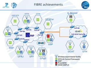


The FIBRE project aims to create a collaborative research space between the EU and Brazil for future internet experimentation, focusing on network infrastructure and distributed applications. It involves members from various universities and institutions engaged in developing and operating experimental facilities. The project's results include technical requirements for infrastructure, experimental pilots, and fostering international collaboration in future internet technologies.