Suplementary Reading
• DigitalDesign
by - John F. Wakerly
– www.ddpp.com - you will find some solutions at this site.
– www.xilinx.com - Xlinix Web site
• Logic and Computer Design Fundamentals
by - M. Morris Mano & Charles R. Kime
• Digital Design
by - M. Morris Mano
• Digital Logic Circuit Analysis and Design
by - Victor P. Nelson, H. Troy Nagle, J. David Irwin & Bill D. Carrol
3.
Digital Electronics
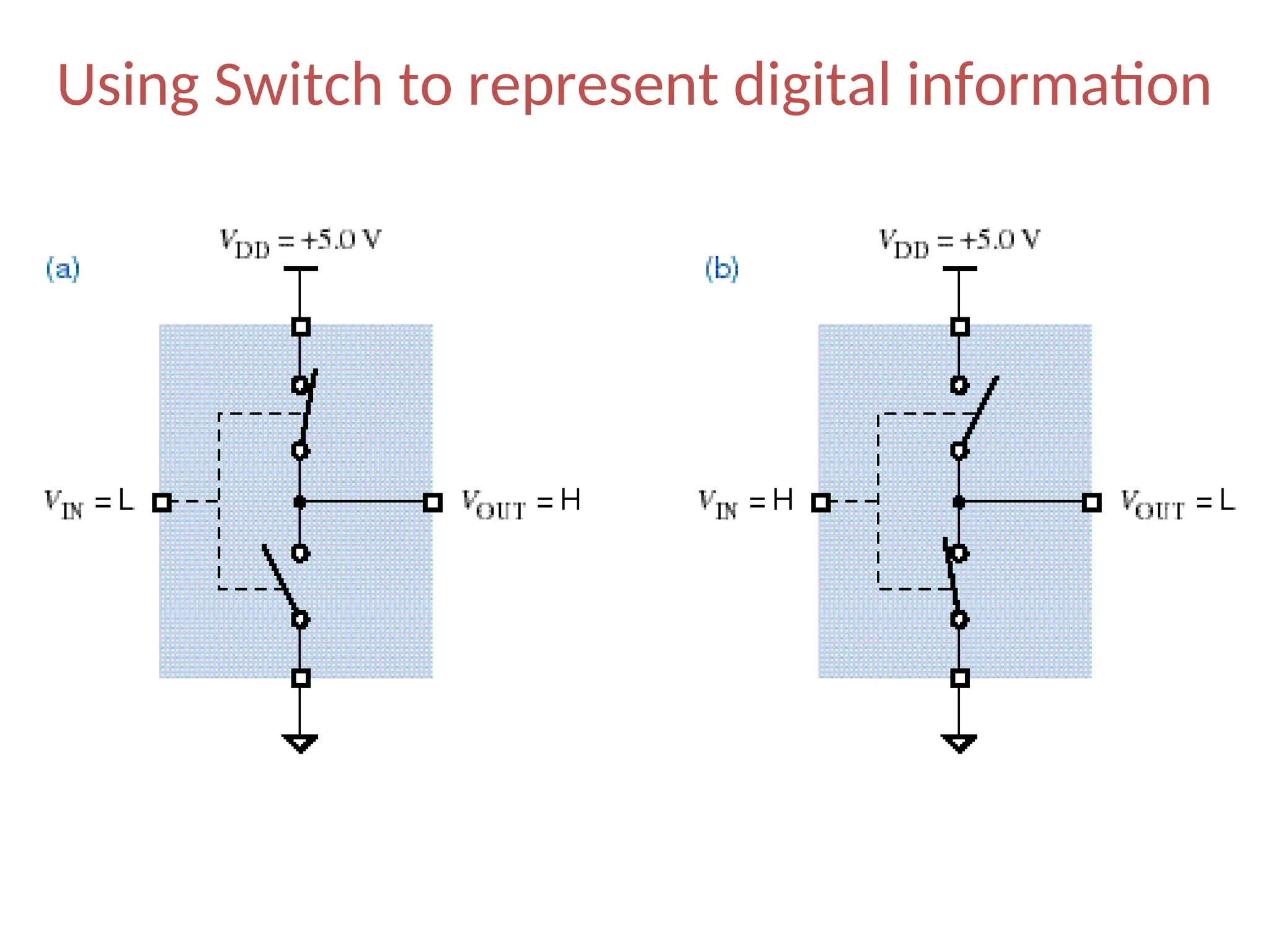
• DigitalElectronics represents information (0, 1) with
only two discrete values.
• Ideally
“no voltage” (e.g., 0v) represents a 0 and
“full source voltage” (e.g., 5v) represents a 1
• Realistically
“low voltage” (e.g., <1v) represents a 0 and
“high voltage” (e.g., >4v) represents a 1
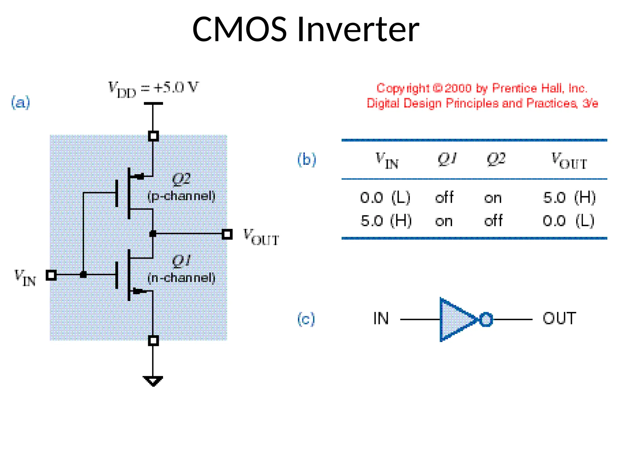
• We achieve these discrete values by using switches.
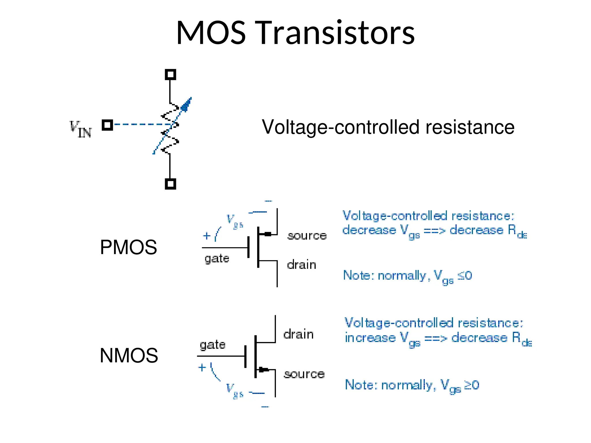
• We use transistor switches, which operates at high
speed, electronically, a small in size.
4.
Analog versus Digital
•Analog systems process time-varying signals that
can take on any value across a continuous range
of voltages (in electrical/electronics systems).
• Digital systems process time-varying signals that
can take on only one of two discrete values of
voltages (in electrical/electronics systems).
– Discrete values are called 1 and 0 (ON and OFF, HIGH
and LOW, TRUE and FALSE, etc.)
5.
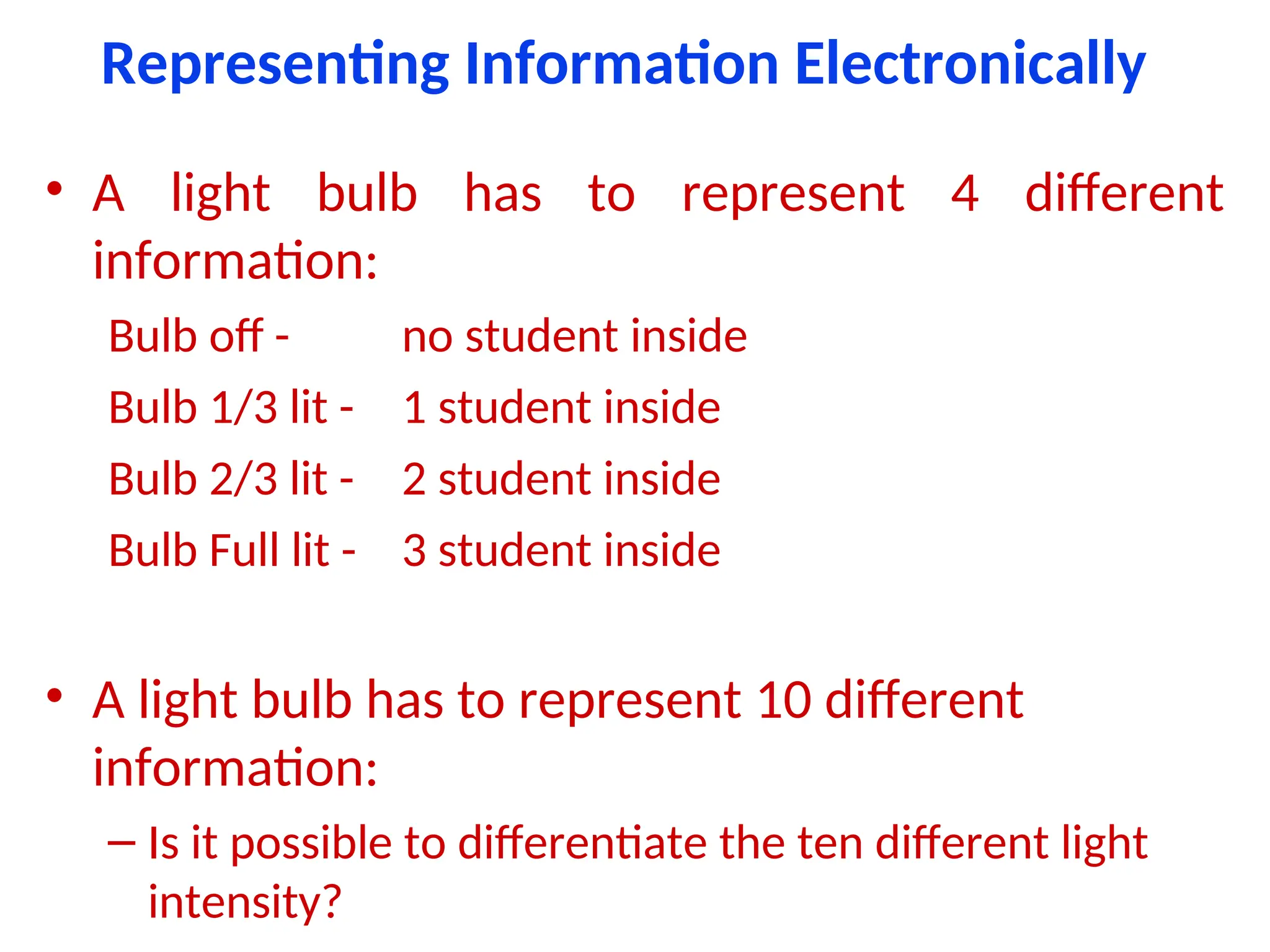
Representing Information Electronically
•A light bulb has to represent 4 different
information:
Bulb off - no student inside
Bulb 1/3 lit - 1 student inside
Bulb 2/3 lit - 2 student inside
Bulb Full lit - 3 student inside
• A light bulb has to represent 10 different
information:
– Is it possible to differentiate the ten different light
intensity?
6.
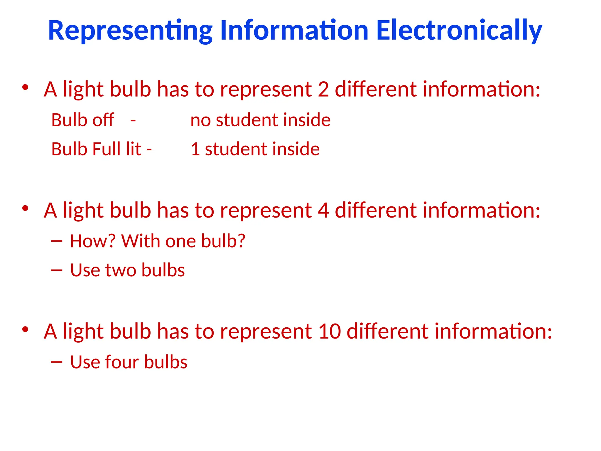
Representing Information Electronically
•A light bulb has to represent 2 different information:
Bulb off - no student inside
Bulb Full lit - 1 student inside
• A light bulb has to represent 4 different information:
– How? With one bulb?
– Use two bulbs
• A light bulb has to represent 10 different information:
– Use four bulbs
Benefits of Digitalover Analog
• Reproducibility
• Not effected by noise means quality
• Ease of design
• Data protection
• Programmable
• Speed
• Economy
9.
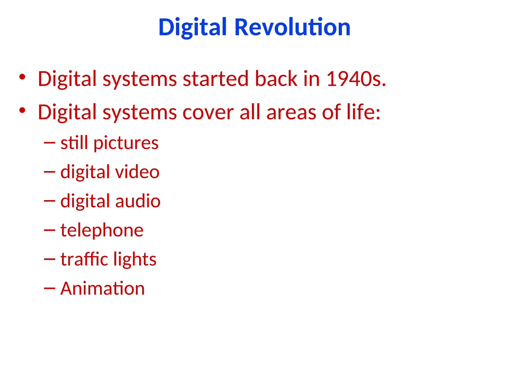
Digital Revolution
• Digitalsystems started back in 1940s.
• Digital systems cover all areas of life:
– still pictures
– digital video
– digital audio
– telephone
– traffic lights
– Animation
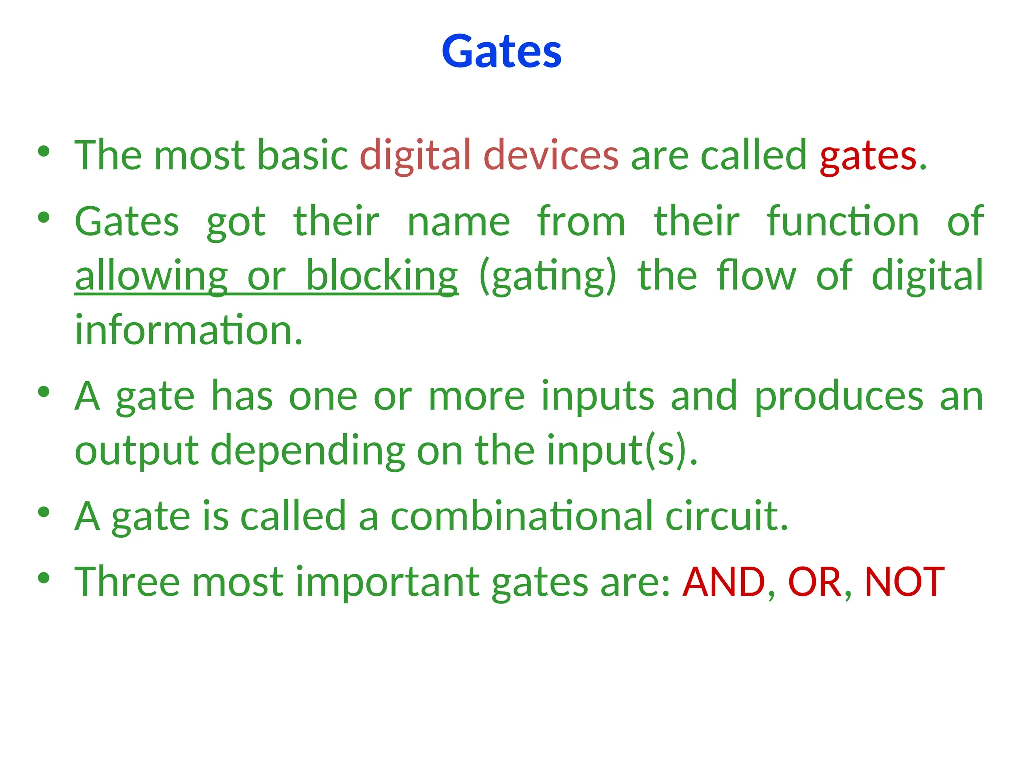
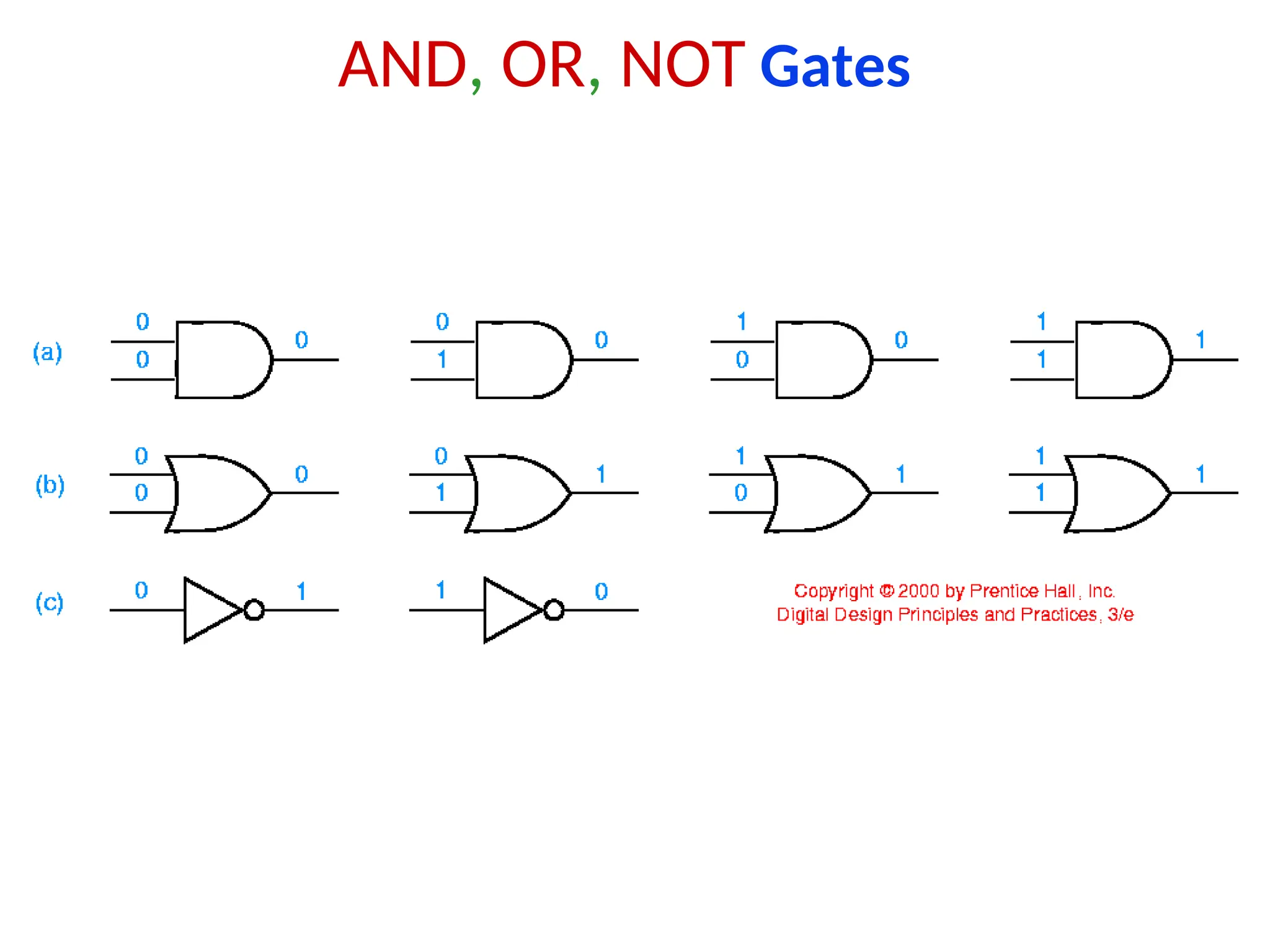
Gates
• The mostbasic digital devices are called gates.
• Gates got their name from their function of
allowing or blocking (gating) the flow of digital
information.
• A gate has one or more inputs and produces an
output depending on the input(s).
• A gate is called a combinational circuit.
• Three most important gates are: AND, OR, NOT
12.
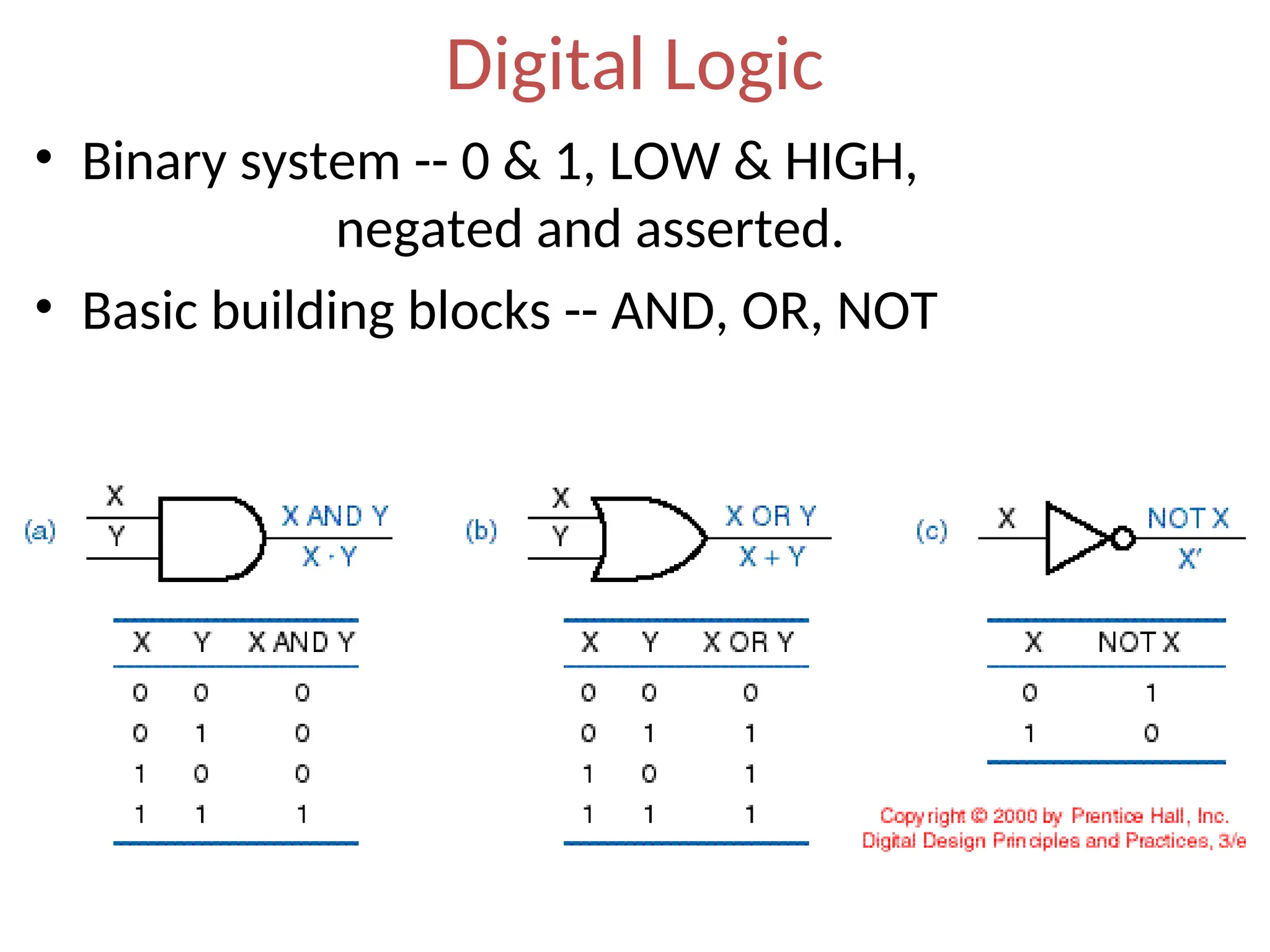
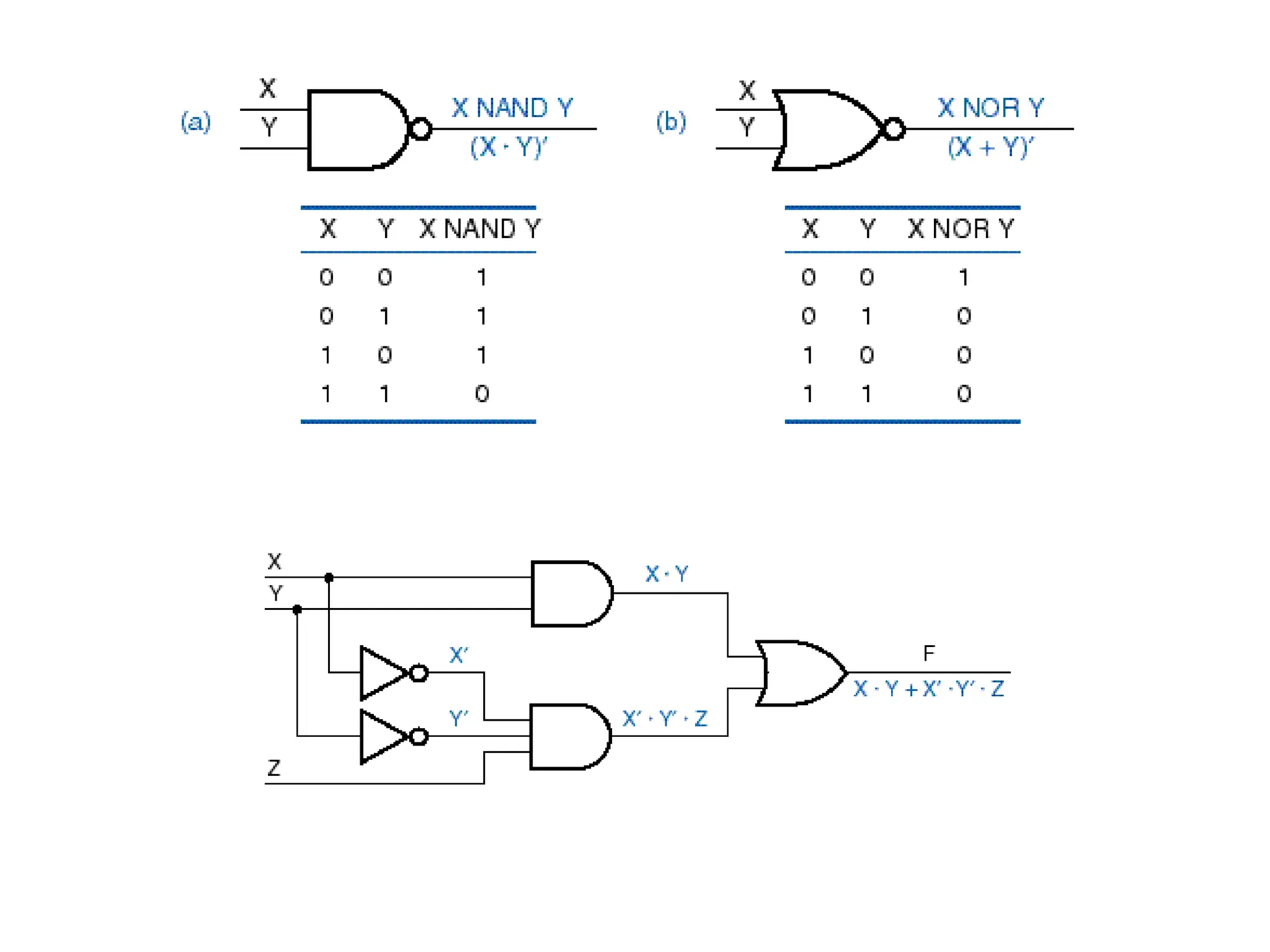
Digital Logic
• Binarysystem -- 0 & 1, LOW & HIGH,
negated and asserted.
• Basic building blocks -- AND, OR, NOT
Digital Abstraction
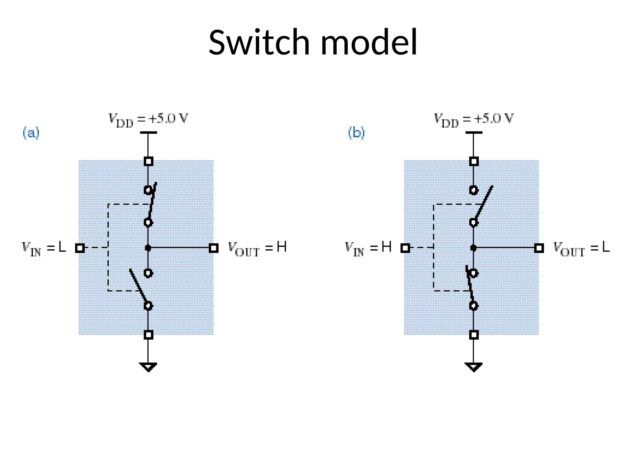
• Itis difficult to make ideal switches means a
switch is completely ON or completely OFF.
• So, we impose some rules that allow analog
behavior to be ignored in most cases, so circuits
can be modeled as if they really did process 0s
and 1s, known as digital abstraction.
• Digital abstraction allows us to associate a noise
margin with each logic values (0 and 1).
19.
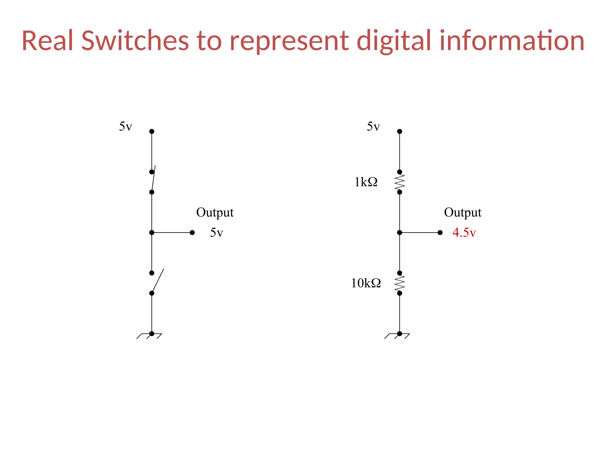
Real Switches torepresent digital information
5v 5v
1k
10k
5v 4.5v
Output Output
20.
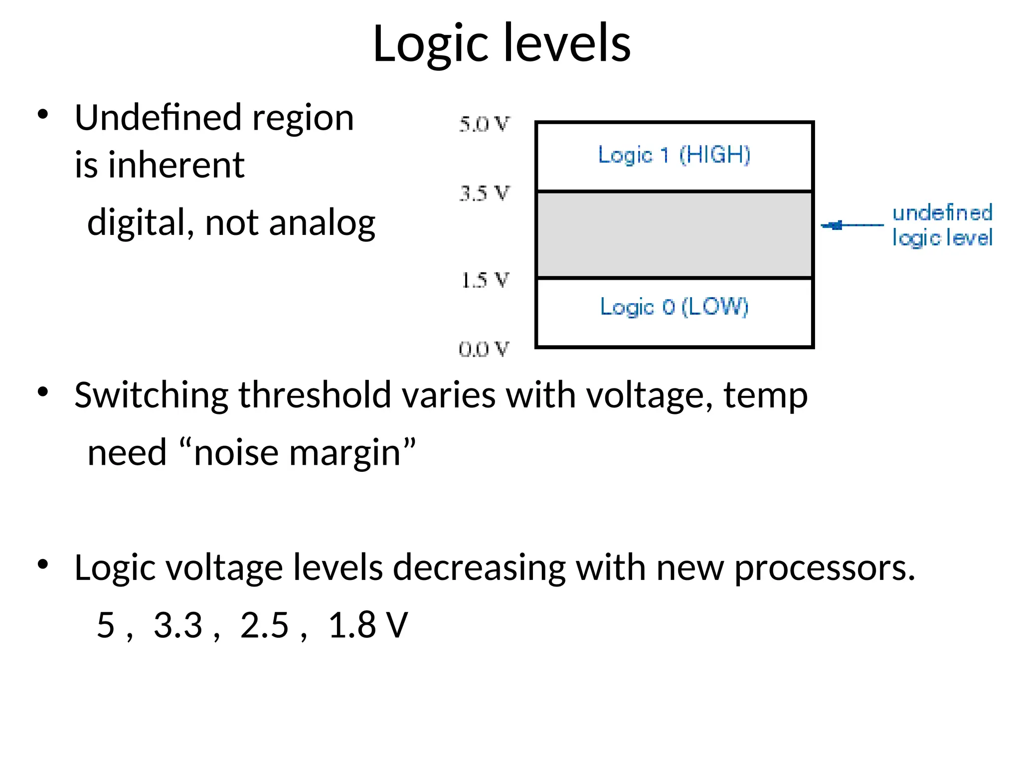
Logic levels
• Undefinedregion
is inherent
digital, not analog
• Switching threshold varies with voltage, temp
need “noise margin”
• Logic voltage levels decreasing with new processors.
5 , 3.3 , 2.5 , 1.8 V
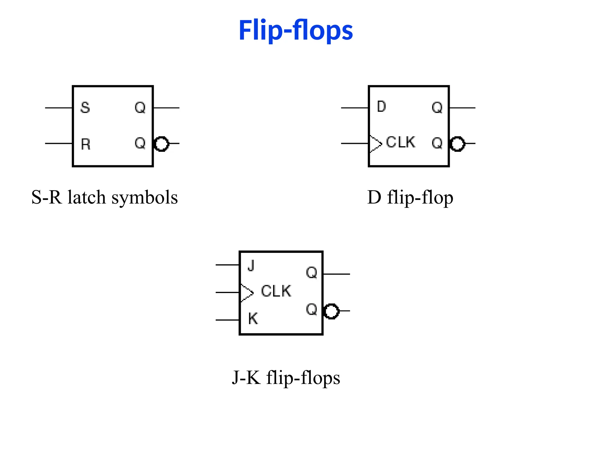
Flip-flops
• A devicethat stores either a 0 or 1.
• Stored value can be changed only at certain
times determined by a clock input.
• New value depend on the current state and it’s
control inputs
• A digital circuit that contains filp-flops is called a
sequential circuit
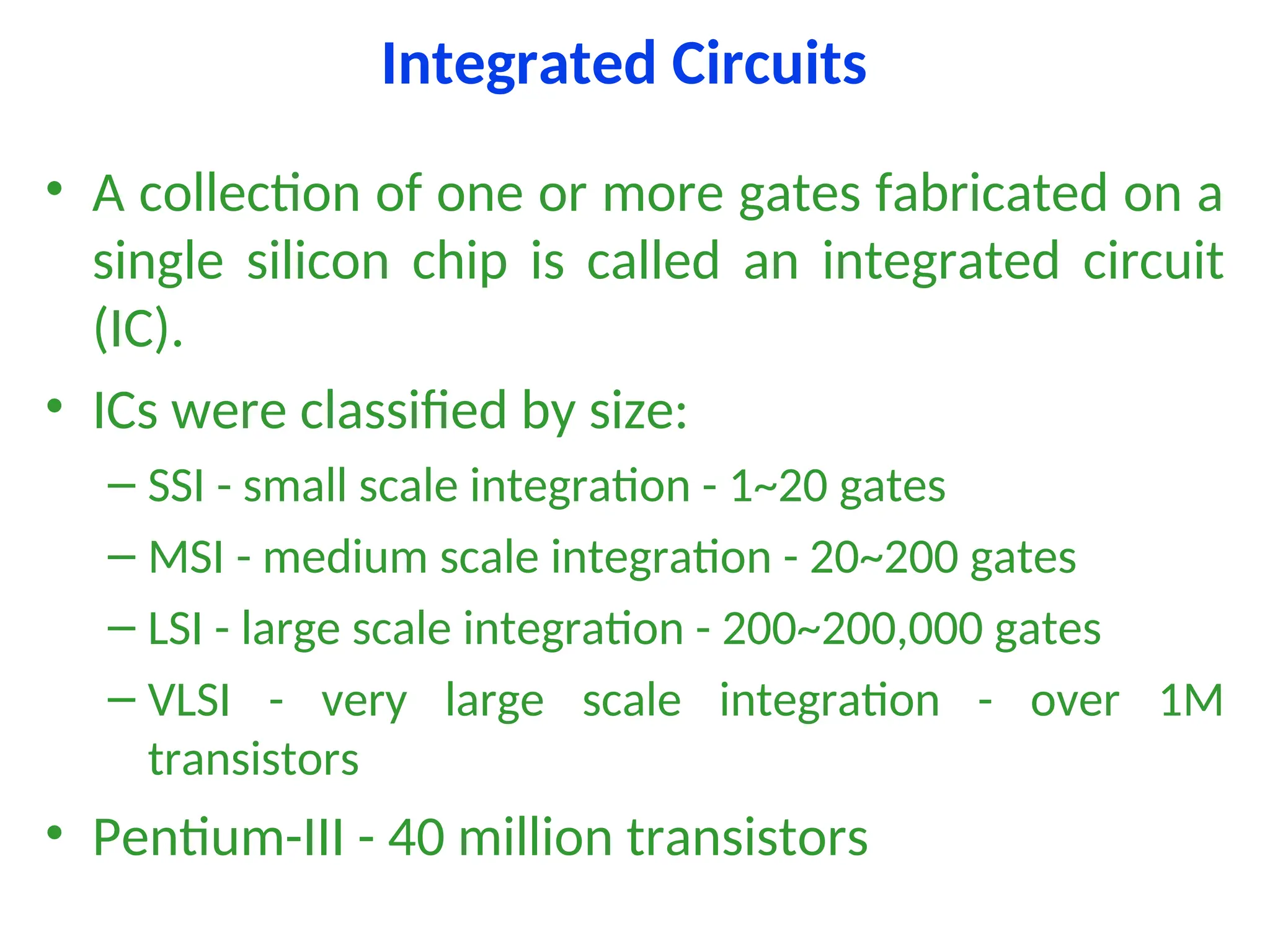
Integrated Circuits
• Acollection of one or more gates fabricated on a
single silicon chip is called an integrated circuit
(IC).
• ICs were classified by size:
– SSI - small scale integration - 1~20 gates
– MSI - medium scale integration - 20~200 gates
– LSI - large scale integration - 200~200,000 gates
– VLSI - very large scale integration - over 1M
transistors
• Pentium-III - 40 million transistors
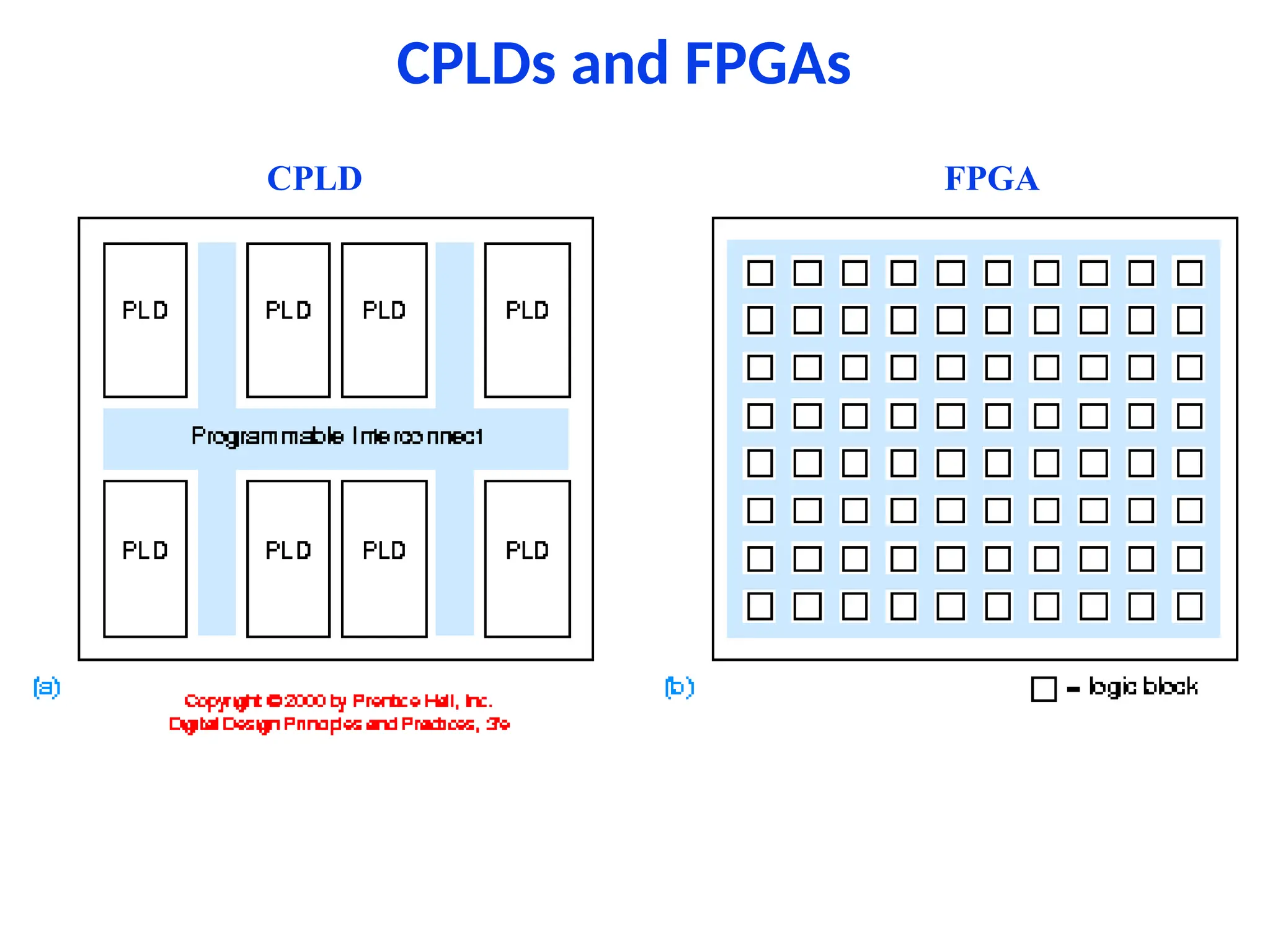
Programmable Logic Devices
•PLDs allow the function to be programmed into
them after they are manufactured.
• Complex PLDs (CPLD) are a collection of PLDs on
the same chip.
• Another programmable logic chip is FPGA - field-
programmable gate arrays.
Application Specific ICs(ASICs)
• Chips designed for a particular application are
called semicustom ICs or application-specific ICs
(ASICs).
• ASICs generally reduce the total component and
manufacturing cost of a product by reducing chip
count, physical size, and power consumption,
and they often provide higher performance.
• But costly if not produced in bulk.
32.
Printed-Circuit Boards
• AnIC is normally mounted on a printed-circuit
board (PCB) that connects it to other ICs in a
system.
• Individual wire connection or traces can be as
narrow as 4 mils with 4 mils spacing (one-
thousandth of an inch)
• Now a days, most of the components use surface
mount technology.
• They are normally layered.
33.
Software Aspects ofDigital Design
• Today software tools are an essential part of digital
design.
• Software tools improve productivity, correctness and
quality of designs
• Software tools are:
– Schematic entry
– HDL (Hardware Description Language) Editors
– Simulators - to verify the behaviour of the design
– Synthesis tools - circuit design
– Timing analyzers and verifiers
34.
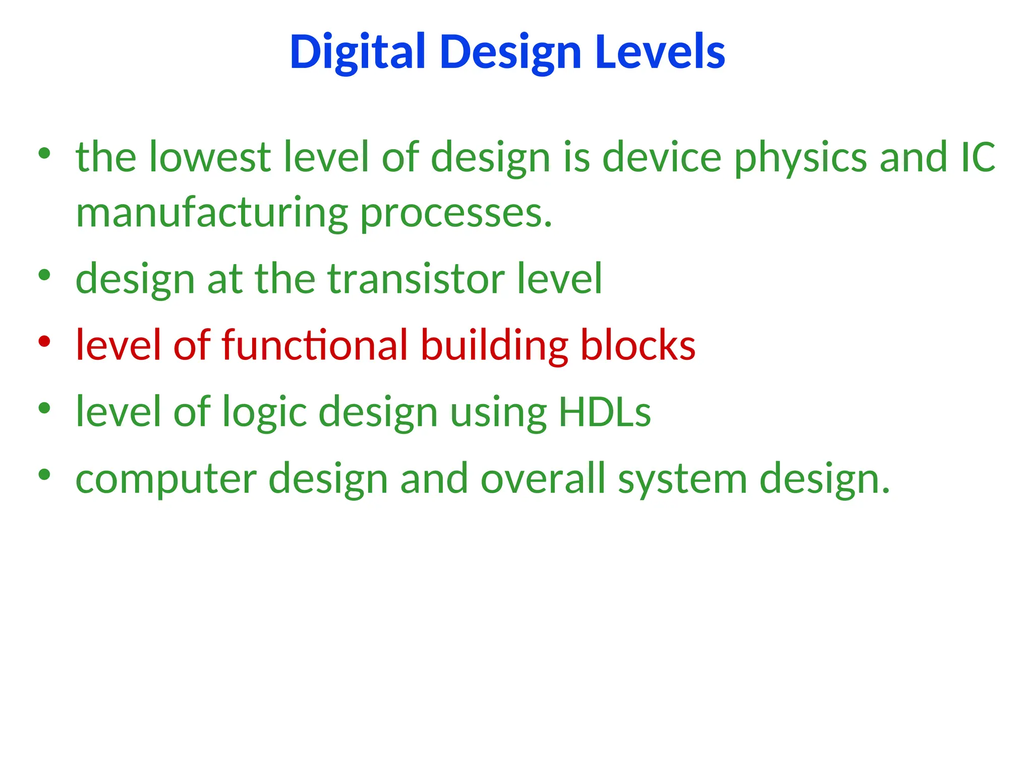
Digital Design Levels
•the lowest level of design is device physics and IC
manufacturing processes.
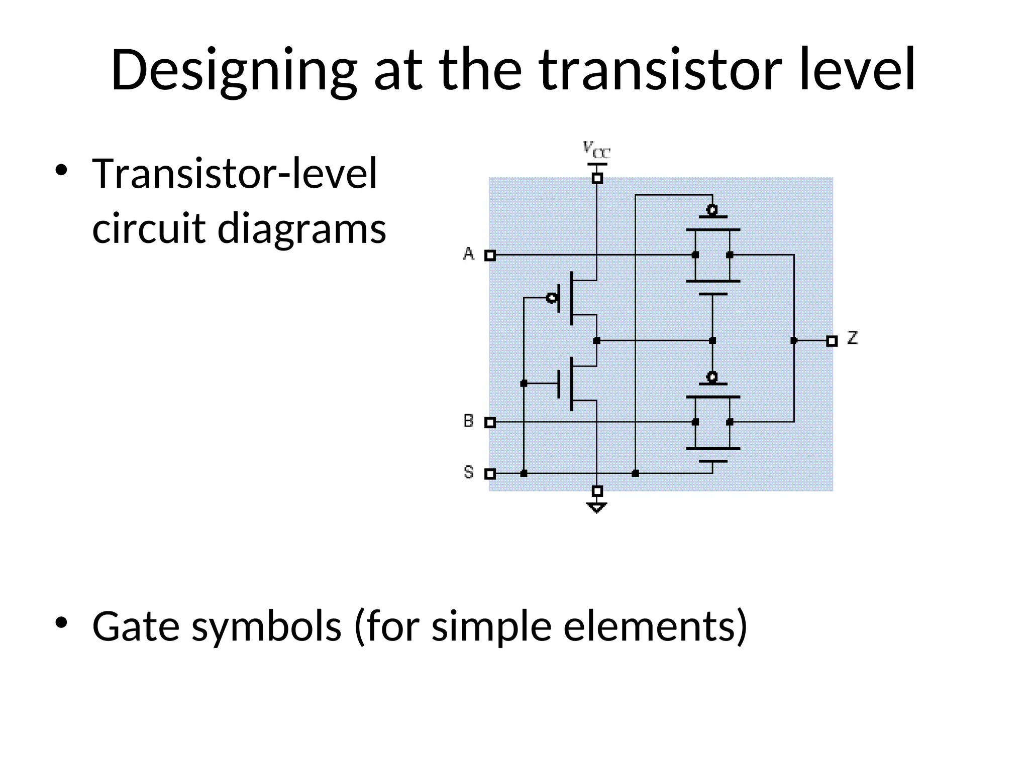
• design at the transistor level
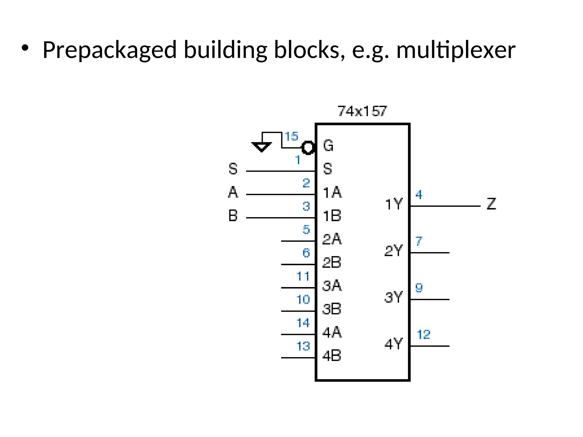
• level of functional building blocks
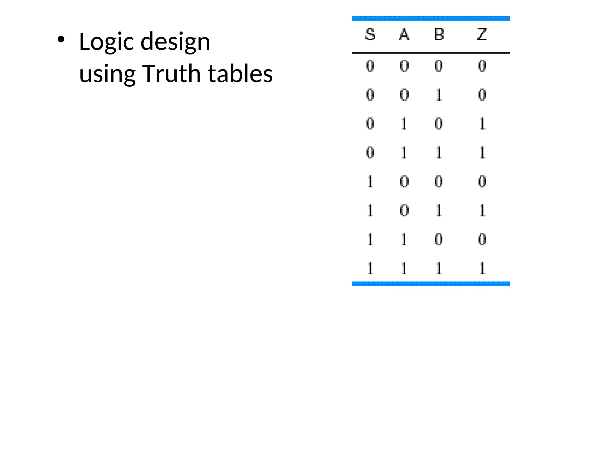
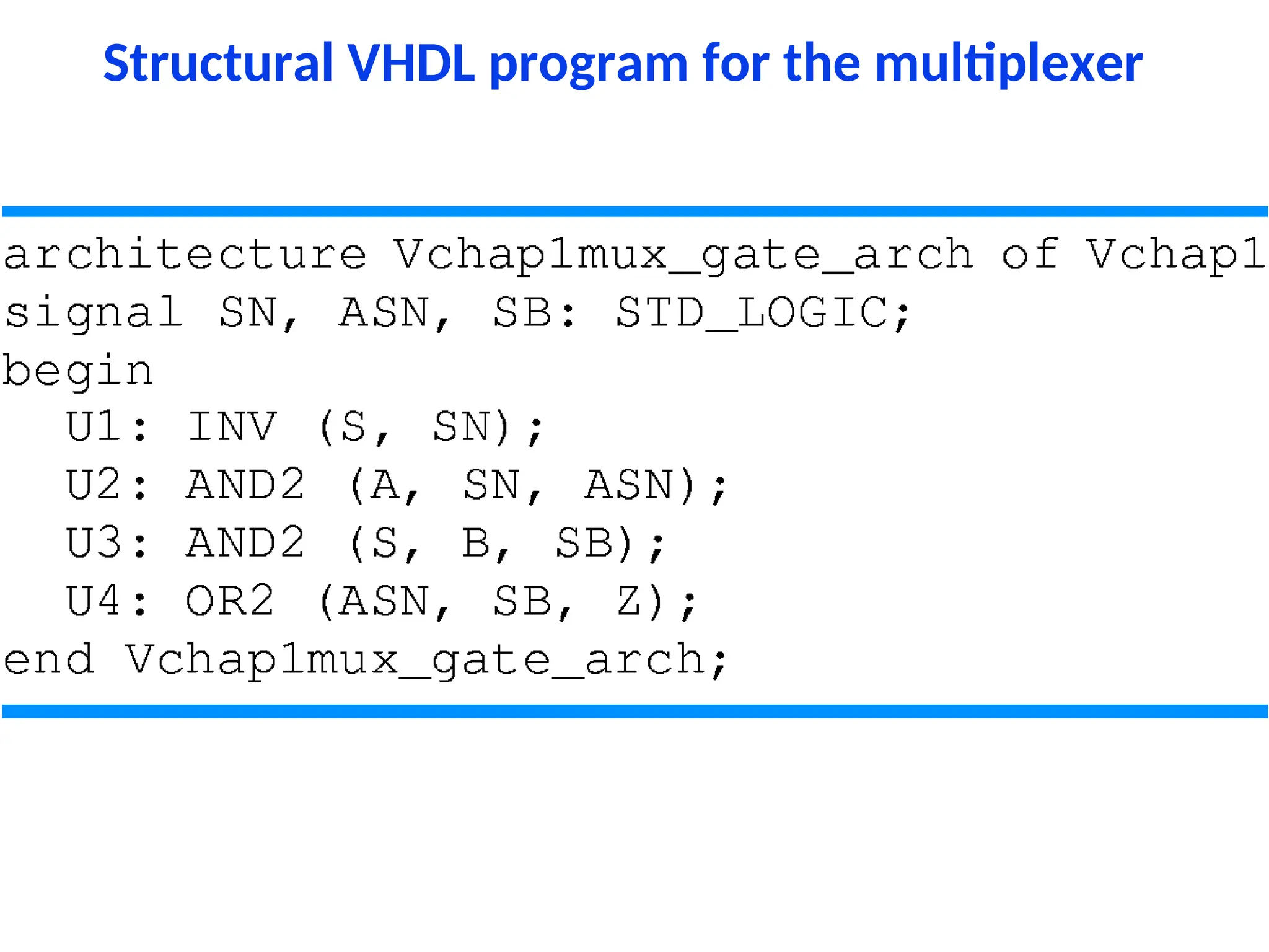
• level of logic design using HDLs
• computer design and overall system design.
35.
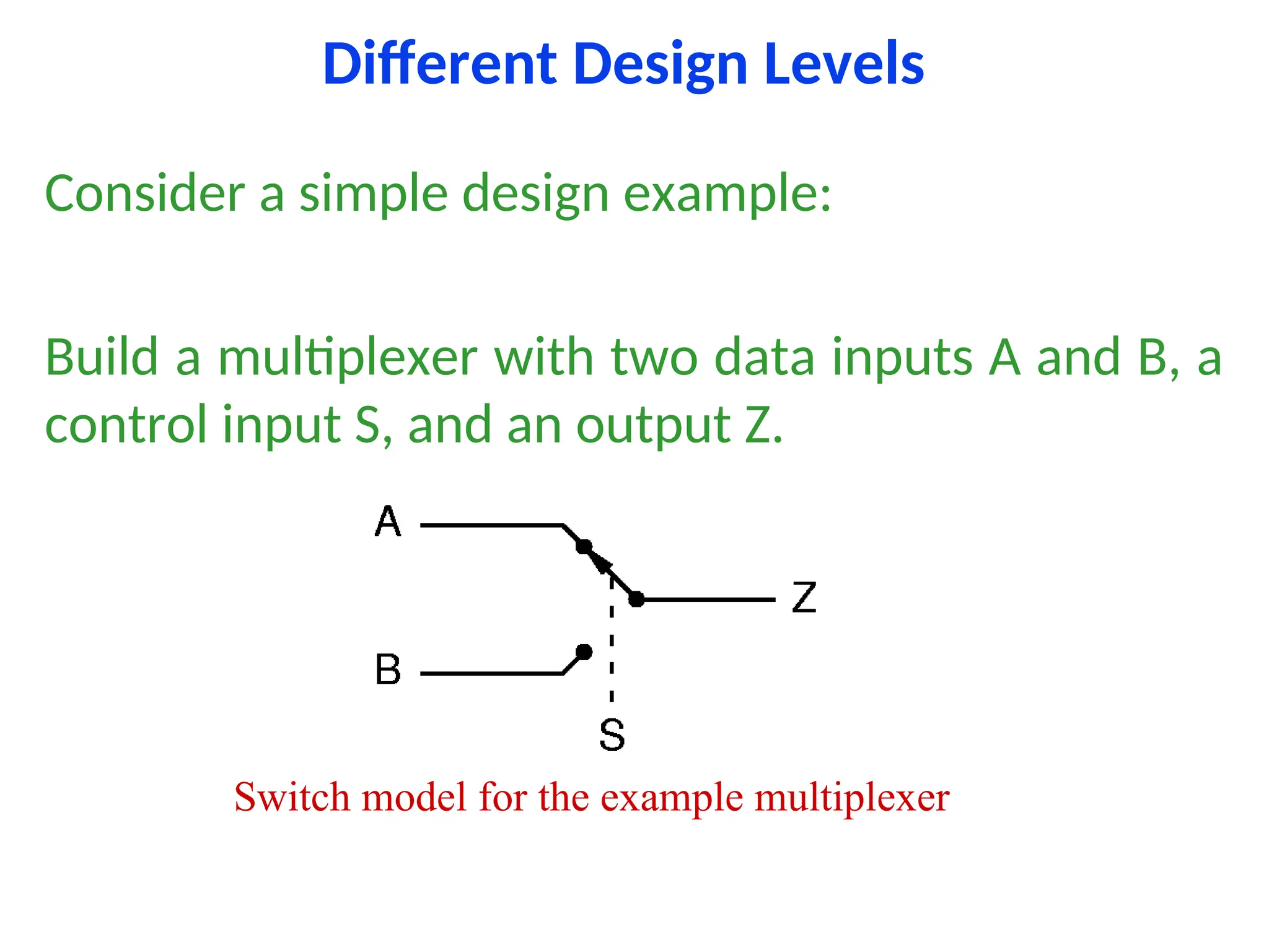
Different Design Levels
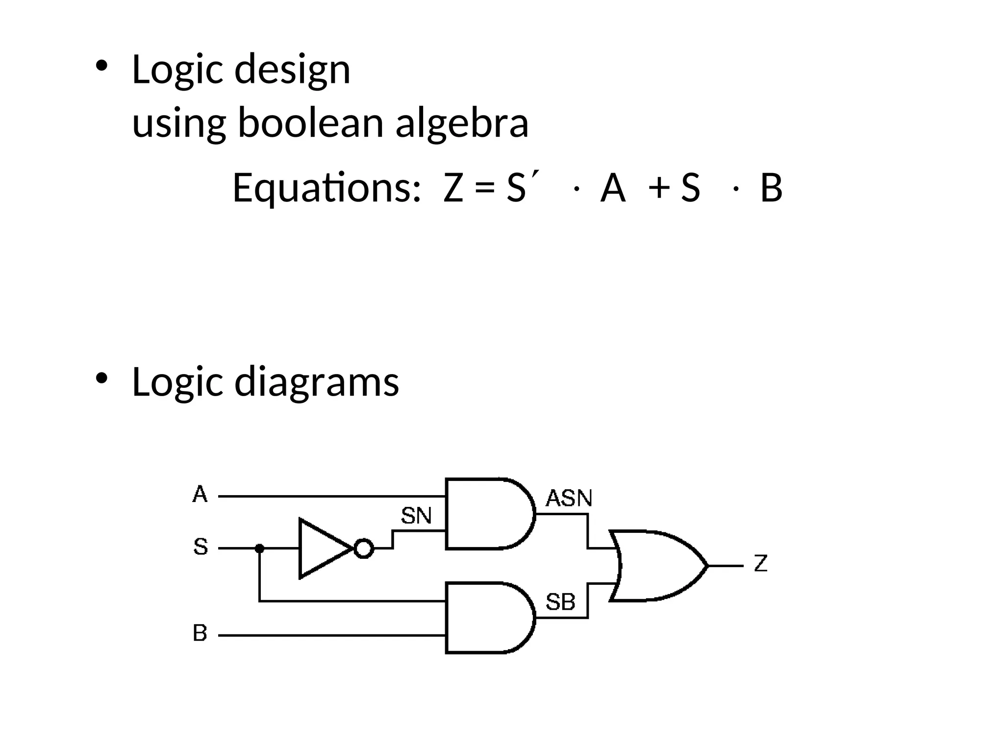
Considera simple design example:
Build a multiplexer with two data inputs A and B, a
control input S, and an output Z.
Switch model for the example multiplexer
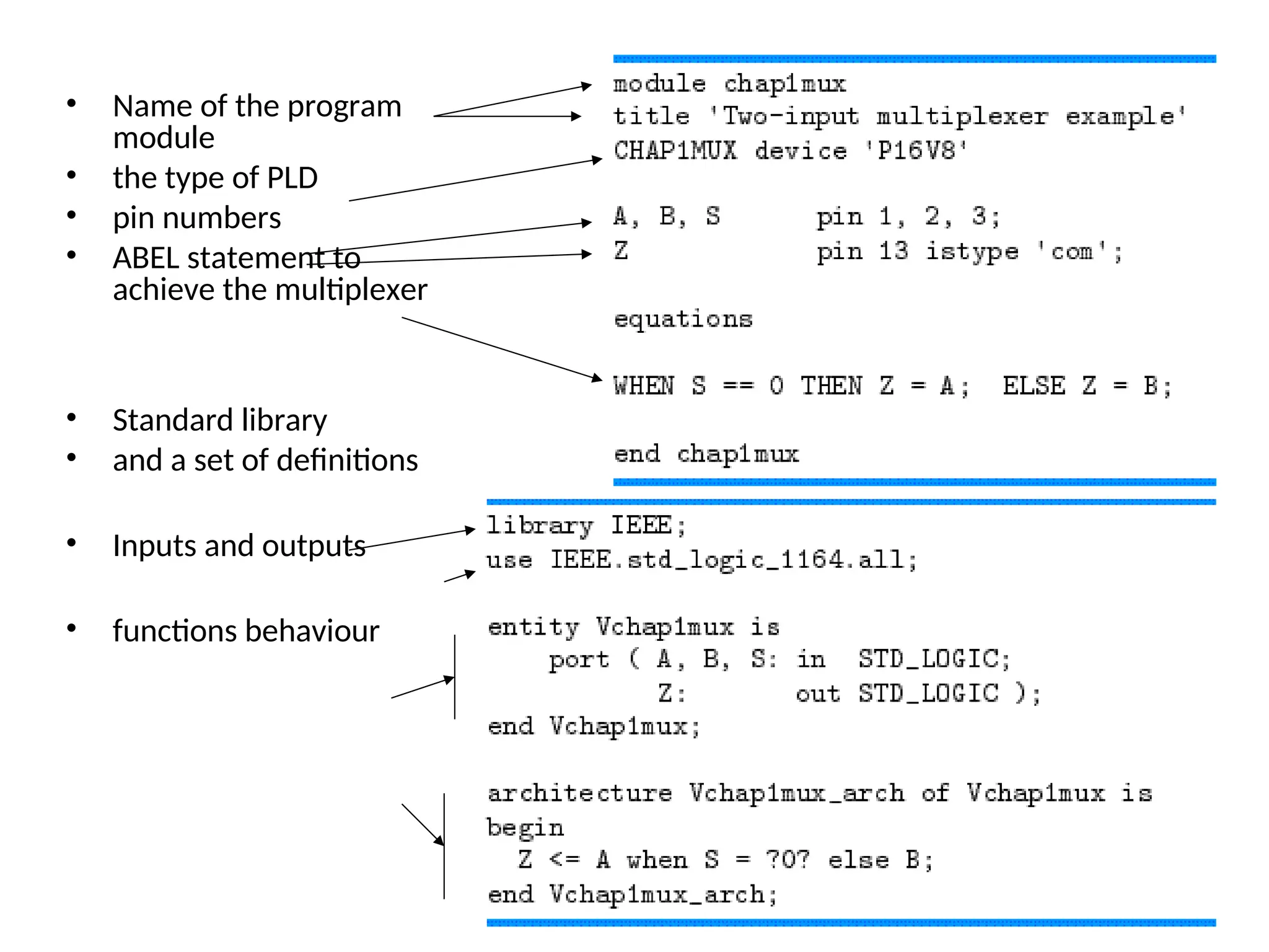
• Name ofthe program
module
• the type of PLD
• pin numbers
• ABEL statement to
achieve the multiplexer
• Standard library
• and a set of definitions
• Inputs and outputs
• functions behaviour
Summery
• Design tominimize cost.
• Rule of thumb is to minimize the number of ICs.
• Though PLDs costs more but uses less PCB area.
• Unless mass production avoid ASIC design.
• Design to solve real life problems.