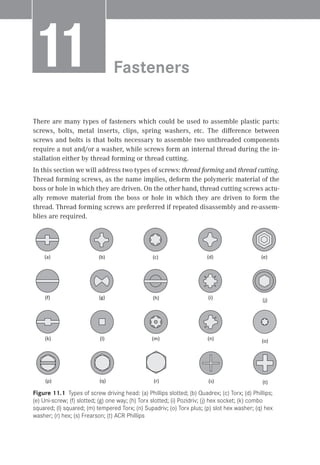
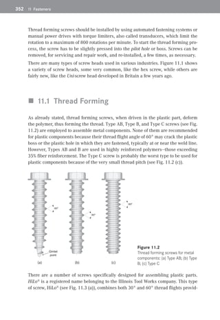
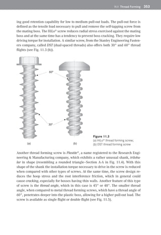
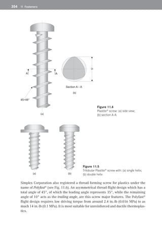
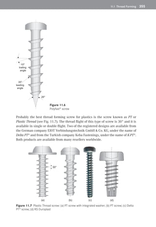
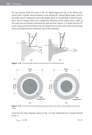
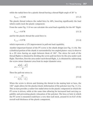
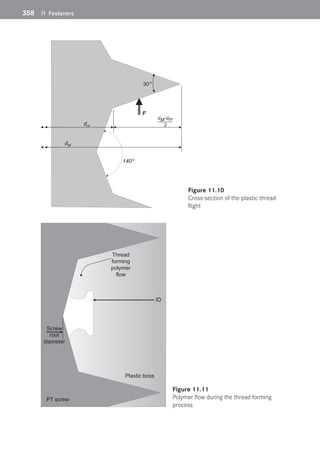
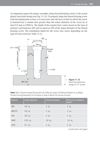
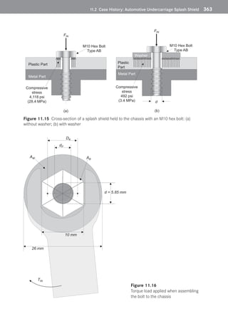
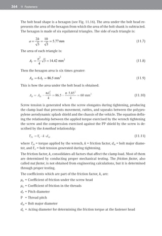
SlideShare a Scribd company logo
There are many types of fasteners which could be used to assemble plastic parts:
screws, bolts, metal inserts, clips, spring washers, etc. The difference between
screws and bolts is that bolts necessary to assemble two unthreaded components
require a nut and/or a washer, while screws form an internal thread during the in-
stallation either by thread forming or thread cutting.
In this section we will address two types of screws: thread forming and thread cutting.
Thread forming screws, as the name implies, deform the polymeric material of the
boss or hole in which they are driven. On the other hand, thread cutting screws actu-
ally remove material from the boss or hole in which they are driven to form the
thread. Thread forming screws are preferred if repeated disassembly and re-assem-
blies are required.
(a) (b) (c) (d) (e)
(f) (g) (h) (i) (j)
(k) (l) (m) (n) (o)
(p) (q) (r) (s) (t)
Figure 11.1 Types of screw driving head: (a) Phillips slotted; (b) Quadrex; (c) Torx; (d) Phillips;
(e) Uni-screw; (f) slotted; (g) one way; (h) Torx slotted; (i) Pozidriv; (j) hex socket; (k) combo
squared; (l) squared; (m) tempered Torx; (n) Supadriv; (o) Torx plus; (p) slot hex washer; (q) hex
washer; (r) hex; (s) Frearson; (t) ACR Phillips
Fasteners
 1
1
352	 11 Fasteners
Thread forming screws should be installed by using automated fastening systems or
manual power drives with torque limiters, also called transducers, which limit the
rotation to a maximum of 800 rotations per minute. To start the thread forming pro-
cess, the screw has to be slightly pressed into the pilot hole or boss. Screws can be
removed, for servicing and repair work, and re-installed, a few times, as necessary.
There are many types of screw heads used in various industries. Figure 11.1 shows
a variety of screw heads, some very common, like the hex screw, while others are
fairly new, like the Uni-screw head developed in Britain a few years ago.
„
„ 11.1 Thread Forming
As already stated, thread forming screws, when driven in the plastic part, deform
the polymer, thus forming the thread. Type AB, Type B, and Type C screws (see Fig.
11.2) are employed to assemble metal components. None of them are recommended
for plastic components because their thread flight angle of 60° may crack the plastic
boss or the plastic hole in which they are fastened, typically at or near the weld line.
However, Types AB and B are used in highly reinforced polymers—those exceeding
35% fiber reinforcement. The Type C screw is probably the worst type to be used for
plastic components because of the very small thread pitch (see Fig. 11.2 (c)).
Gimlet
point
60o
60o
60o
(a) (b) (c)
 Figure 11.2 
Thread forming screws for metal
components: (a) Type AB; (b) Type
B; (c) Type C
There are a number of screws specifically designed for assembling plastic parts.
HiLo®
is a registered name belonging to the Illinois Tool Works company. This type
of screw, HiLo®
(see Fig. 11.3 (a)), combines both 30° and 60° thread flights provid-
11.1 Thread Forming	 353
ing good retention capability for low to medium pull-out loads. The pull-out force is
defined as the tensile load necessary to pull and remove the self-tapping screw from
the mating boss. The HiLo® screw reduces radial stress exercised against the mating
boss and at the same time has a tendency to prevent boss cracking. They require low
driving torque for installation. A similar screw, from the Stanley Engineering Fasten-
ers company, called DST (dual-spaced threads) also offers both 30° and 60° thread
flights (see Fig. 11.3 (b)).
60o
30o
(b)
(a)
 Figure 11.3 
(a) HiLo®
thread forming screw;
(b) DST thread forming screw
Another thread forming screw is Plastite®
, a name registered to the Research Engi-
neering  Manufacturing company, which exhibits a rather unusual shank, trilobu-
lar in shape (resembling a rounded triangle—Section A-A in Fig. 11.4). With this
shape of the shank the installation torque necessary to drive in the screw is reduced
when compared with other types of screws. At the same time, the screw design re-
duces the hoop stress and the root interference friction, which in general could
cause cracking, especially for bosses having thin walls. Another feature of this type
of screw is the thread angle, which in this case is 45° or 48°. The smaller thread
angle, when compared to metal thread forming screws, which have a thread angle of
60°, penetrates deeper into the plastic boss, allowing for a higher pull-out load. The
screw is available as single flight or double flight (see Fig. 11.5).
354	 11 Fasteners
A A
Section A - A
D
45÷48°
(a)
(b)
 
Figure 11.4 
Plastite®
screw: (a) side view;
(b) section A-A
(a) (b)
 
Figure 11.5 
Trilobular Plastite® screw with: (a) single helix;
(b) double helix
Simplex Corporation also registered a thread forming screw for plastics under the
name of Polyfast® (see Fig. 11.6). An asymmetrical thread flight design which has a
total angle of 45°, of which the leading angle represents 35°, while the remaining
angle of 10° acts as the trailing angle, are this screw major features. The Polyfast®
flight design requires low driving torque from around 2.4 in.·lb (0.016 MPa) to as
much 14 in.·lb (0.1 MPa). It is most suitable for unreinforced and ductile thermoplas-
tics.
11.1 Thread Forming	 355
10o
trailing
angle
26o
35o
leading
angle
 Figure 11.6 
Polyfast® screw
Probably the best thread forming screw for plastics is the screw known as PT or
Plastic Thread (see Fig. 11.7). The thread flight of this type of screw is 30° and it is
available in single or double flight. Two of the registered designs are available from
the German company EJOT Verbindungstechnik GmbH  Co. KG, under the name of
Delta PT® and from the Turkish company Keba Fastenings, under the name of K-PT®.
Both products are available from many resellers worldwide.
(a) (b) (c)
30°
(d)
Figure 11.7 Plastic Thread screw: (a) PT screw with integrated washer; (b) PT screw; (c) Delta
PT® screw; (d) RS Duroplast
356	 11 Fasteners
The key feature of the PT screw is the 30° flight angle (see Fig. 11.8). When com-
pared with a regular thread forming screw having 60° thread flight angle, used to
assemble metal components and some highly glass or aramid fiber reinforced poly-
mers, the PT design allows for a significant reduction of the radial stress, while at
the same time increasing somewhat the pull-out load. Figure 11.9 shows that the PT
screw design penetrates deeper into the plastic boss or hole, thus reducing the hoop
stress and improving the retention load of the assembly.
FRadial
R
FAxial
30o
60o
rST
30o
R
FAxial
15o
FRadial
rPT
(a) (b)
Figure 11.8 PT thread flight detail compared with the standard thread
Boss
dia
Screw
root
dia
Flight
engagement
(a)
Boss
dia
Screw
root
dia
Flight
engagement
(b)
Figure 11.9 (a) Standard thread flight penetration detail; (b) plastic thread flight penetration
detail
From the free body diagram shown in Fig. 11.8 the radial force for standard thread
of 60° is
 (11.1)
11.1 Thread Forming	 357
while the radial force for a plastic thread having a thread flight angle of 30° is
 (11.2)
The plastic thread reduces the radial force by 48%, lowering significantly the load
which could crack the plastic component.
From the same Fig. 11.8 we can calculate the axial load capability for the 60° flight:
 (11.3)
and for the plastic thread the axial force is:
 (11.4)
which represents a 12% improvement in pull-out load capability.
Another important feature of the PT screw is the shank design (see Fig. 11.10). The
cylindrical portion of the shank is surrounded by two angled planes—easy to observe
in a 2D view—having an angle between them of 140°. The stress for each of the
thread flights is obtained by dividing the screw pull-out force by the area under each
flight. Therefore, first the area under each thread flight, A, is obtained by subtracting
the screw minor diameter area from its major diameter area:
(11.5)
Then the pull-out stress is:
(11.6)
When the screw is driven and forming the thread in the mating hole or boss, the
140° angle allows for the plastic/elastic deformation of the polymer (see Fig. 11.11).
This in turn provides a rather low radial stress in the plastic component in which the
PT screw is driven, while at the same time allowing for increased load carrying ca-
pability and preventing plastic relaxation of the polymer. The boss or hole in which
the PT screw is mounted could have a very thin wall stock, around 0.5 to 0.67 of the
overall wall thickness of the plastic component.
358	 11 Fasteners
30o
F
140o
dM
dm
dM-dm
2
 Figure 11.10 
Cross-section of the plastic thread
flight
Plastic boss
PT screw
ID
Screw
root
diameter
Thread
forming
polymer
flow
 Figure 11.11 
Polymer flow during the thread forming
process
11.1 Thread Forming	 359
An important aspect for proper assembly using thread forming screws is the actual
plastic boss /hole design (see Fig. 11.12). To properly align the thread forming screw
with the mating hole or boss, it is necessary that the boss or hole in which the screw
is fastened has a counter bore greater than the minor diameter of the screw by at
least 0.2 mm or 0.008 in. The depth of the counter bore varies based on the type of
polymer used between 30% and as much as 50% of the major diameter of the thread
forming screw. The installation depth for the screw also varies depending on the
type of resin used (see Table 11.1).
t
OD
d +0.2 mm
M
0.3 ÷ 0.5dM
1
o
1
o
r = 0.5t
r = 0.25t
0.67t
y
=
installation
depth
dBoss
Min 0.5t
Counter
bore
 Figure 11.12 
Recommended boss
design for PT screws
Table 11.1 Recommended Dimensions for Different Types of Polymers Based on dM (Major
Thread Forming Diameter) for the Boss or Hole in Which the Screw Is Driven
Polymer Inside diameter Outside diameter Minimum installation
depth
ABS 0.8 · dM 2 · dM 2 · dM
ABS/PC 0.8 · dM 2 · dM 2 · dM
ASA 0.8 · dM 2 · dM 2 · dM
HDPE 0.75 · dM 1.8 · dM 1.8 · dM
LDPE 0.7 · dM 2 · dM 2 · dM
(continuation next page)
360	 11 Fasteners
Polymer Inside diameter Outside diameter Minimum installation
depth
PA 4.6 0.7 · dM 1.85 · dM 1.8 · dM
PA 6 0.75 · dM 1.85 · dM 1.7 · dM
PA 6 GR 0.8 · dM 2 · dM 1.9 · dM
PA 66 0.75 · dM 1.85 · dM 1.7 · dM
PA 66 GR 0.8 · dM 2 · dM 1.8 · dM
PBT 0.75 · dM 1.85 · dM 1.7 · dM
PBT GR 0.8 · dM 1.8 · dM 1.7 · dM
PC 0.9 · dM 2.5 · dM 2.2 · dM
PC GR 0.9 · dM 2.2 · dM 2 · dM
PET 0.75 · dM 1.85 · dM 1.7 · dM
PET GR 0.8 · dM 1.8 · dM 1.7 · dM
POM 0.75 · dM 1.95 · dM 2 · dM
POM GR 0.8 · dM 1.95 · dM 2 · dM
PP 0.7 · dM 2 · dM 2 · dM
PP GR 0.72 · dM 2 · dM 2 · dM
PP TR 0.72 · dM 2 · dM 2 · dM
PPO 0.85 · dM 2.5 · dM 2.2 · dM
PS 0.8 · dM 2 · dM 2 · dM
PVC 0.8 · dM 2 · dM 2 · dM
SAN 0.77 · dM 2 · dM 1.9 · dM
It should be noted that when employing self-tapping screws for an assembly, it is
very important to use a torque limiter for the driving tool which holds the screw
socket. As shown in Fig. 11.13, the stripping zone can very easily be reached with-
out a proper torque limiter. Keeping the screw driving tool speeds between 300 rota-
Table 11.1 Recommended Dimensions for Different Types of Polymers Based on dM (Major
Thread Forming Diameter) for the Boss or Hole in Which the Screw Is Driven (continuation)
11.1 Thread Forming	 361
tions per minute (rpm) at the low end and 800 rpm at the high end ensures that the
plastic material is not damaged, thus providing reliable installations. The heat gen-
erated during the fastening process can break down the plastic by melting it, thus
reducing the required torque levels stipulated by the specific application. Speeds
should be kept below 800 rpm so that the polymer does not melt, thereby destroying
the plastic component. To reduce or even eliminate the eventuality of screw strip-
ping, the ratio between stripping torque and driving torque should be minimized.
Driving guns activated pneumatically have large torque variance even when a torque
controller is employed. Tolerance for such torque limiters varies between ±15% at the
low end and as much as ±20% at the high end of the required set torque. Electronic
tools, activated electrically, provide much greater accuracy in the range of ±2–4%.
Fully automated electric tools should have a drive to strip ratio of 1 to 5. For hand
tools the ratio is lower, from 1 to 2.
Penetration depth
Torque
Zone 1 - Thread forming
Zone 2 - Clamping
Zone 3 - Stripping
Zone 1 Zone 2 Zone 3
T1
T1
T2
T3
T3
T2
Figure 11.13 Screw stripping zone
As a rule of thumb, the longer the screw, the higher the pull-out forces and strip
torques are. However, the improvement in load bearing is not directly proportional
to the length of the screw utilized.
Thread forming screws are inexpensive and quite reliable, allowing assembly and
disassembly of dissimilar polymers up to 10 times. At the same time, components
assembled with thread forming screws are prone to stress concentrations at the
joined location. When employing screws to assemble components the increased la-
bor costs could become a major issue.
362	 11 Fasteners
„
„ 11.2 
Case History: Automotive Undercarriage
Splash Shield
European original equipment manufacturers (OEMs) had to use splash shields (see
Fig. 11.14) under their vehicles in order to improve the aerodynamics and at the
same time to increase the gas mileage, the main reason being the high cost of gaso-
line and diesel fuels when compared with North America. The automobiles with
splash shields under the carriage appeared in the North American marketplace in
the 1980s. Then, a few years later, other car manufacturers, from Asia, started using
splash shields to improve the gas mileage for their vehicles as well.
 Figure 11.14 
Typical undercarriage
splash shield
Almost all splash shields use commodity polymers like polypropylene or polyethyl-
ene. However, in most cases, the polymers employed are recycled resins. Depending
on how many heat histories the polymer was exposed to during the manufacturing
process, the resin mechanical properties could drop by as much as 50%. When
­
recycled polymers are used, the number of heat histories (the number of times the
polymer passes through the injection molding press) should be kept well below
seven.
An OEM from Asia had used a recycled unreinforced polypropylene resin to manu-
facture an undercarriage splash shield for one of their vehicles. To assemble the
shield to the chassis of the vehicle a metric hex bolt without washer was used (see
Fig. 11.15 (a)). Many vehicles developed shield failures during the warranty period.
They were breaking just underneath the bolt head, holding the shield to the chassis,
at the weld line.
11.2 Case History: Automotive Undercarriage Splash Shield	 363
M10 Hex Bolt
Type AB
Plastic Part
Metal Part
FIN
Compressive
stress
4,118 psi
(28.4 MPa)
Washer
d
FIN
M10 Hex Bolt
Type AB
Plastic
Part
Metal Part
Compressive
stress
492 psi
(3.4 MPa)
(a)
Figure 11.15 Cross-section of a splash shield held to the chassis with an M10 hex bolt: (a)
without washer; (b) with washer
d = 5.85 mm
26 mm
AW AB
10 mm
dP
DK
TIN
 Figure 11.16 
Torque load applied when assembling
the bolt to the chassis
364	 11 Fasteners
The bolt head shape is a hexagon (see Fig. 11.16). The area under the bolt head re­
presents the area of the hexagon from which the area of the bolt shank is subtracted.
The hexagon is made of six equilateral triangles. The side of each triangle is:
(11.7)
The area of each triangle is:
(11.8)
Then the hexagon area is six times greater:
(11.9)
This is how the area under the bolt head is obtained:
(11.10)
Screw tension is generated when the screw elongates during tightening, producing
the clamp load that prevents movement, rattles, and squeaks between the polypro-
pylene aerodynamic splash shield and the chassis of the vehicle. The equation defin-
ing the relationship between the applied torque exercised by the wrench tightening
the screw and the compression exercised against the PP shield by the screw is de-
scribed by the k-method relationship:
(11.11)
where TIN = torque applied by the wrench, k = friction factor, dM = bolt major diame-
ter, and FC = bolt tension generated during tightening.
The friction factor, k, consolidates all factors that affect the clamp load. Most of them
are determined by conducting proper mechanical testing. The friction factor, also
called nut factor, is not obtained from engineering calculations, but it is determined
through proper testing.
The coefficients which are part of the friction factor, k, are:
μk	=	Coefficient of friction under the screw head
μG	=	Coefficient of friction in the threads
dP	=	Pitch diameter
P	 =	Thread pitch
dM	=	Bolt major diameter
dk	 =	Acting diameter for determining the friction torque at the fastener head
11.2 Case History: Automotive Undercarriage Splash Shield	 365
Thus, the value of k is obtained from:
(11.12)
and consequently the compression load under the bolt head, FC, is:
(11.13)
This, in turn, generates the compressive stress, σC, against the polypropylene shield,
when a bolt without washer is used:
(11.14)
By using a washer having a 26 mm outside diameter, the compressive stress exer-
cised against the shield is greatly reduced.
The area under the washer is:
(11.15)
The compressive load, being the same as before, generates a much lower compres-
sive stress:
(11.16)
The compressive stress generated by the torque applied to clamp the shield to the
chassis, when using a washer under the bolt head, lowers the load by over 88%. Prob-
ably the best unreinforced polypropylene has a stress capability of around 5,000 psi
or about 34.5 MPa. The undercarriage splash shield, in this case, was made of recy-
cled polypropylene resin having a much lower stress carrying capability—about half
or around 2,500 psi or 17 MPa. Furthermore, around each molded-in hole, for as-
sembly screws, in the shield exists a weld or knit line, created by the advancing
flows of resin during the injection molding process, which could reduce the stress
capability by another 50% to around 1,250 psi or 8 MPa (see Fig. 11.17 (a)).
A weld line forms when frozen layers at the front of each advancing flow front meet,
melt, and then re-freeze again within the component being molded. The molecular
chains within the polymer orient themselves perpendicular to the flow front at the
weld line. It is the sharp difference of the molecular chain orientation at the weld
which causes the significant decrease in strength. If the gate location can be changed,
one possibility to improve the weld line strength would be to generate a weld line
followed by a meld line during the injection molding cycle time (see Fig. 11.17 (b)).
366	 11 Fasteners
Gate
(Melt)
Weak region
(a)
Gate
(Melt)
Weld
line
Meld
line
Stronger region
(b)
 Figure 11.17 
Formation schematics of:
(a) weld line; (b) weld line
and meld line
As a result of the vibration created by the vehicle when driven, the splash shield
made of recycled PP was failing because the stress exercised by the M10 bolt with-
out washer was much greater than the resin capability. The Asian OEM started using
a washer which translated into reducing the compressive stress load under the
washer and M10 hex bolt by a factor of nine with no warranty concerns.
There are injection molding processing steps, tooling changes, and plastic part de-
sign changes which can be applied to improve the weld line strength as mentioned
above. A meld line occurs when two advancing molten resin flow fronts of the molten
polymer inside the mold during the injection stage of the molding process blend to-
gether at an angle greater than 135°. Figure 11.18 shows a component where a meld
line forms.
Meld lines are stronger than weld lines and offer fewer defects that are visible of the
surface of the plastic component.
Consistent meld lines are challenging to obtain; however, it is possible to attain them
by changing the polymer injection location, also called the gate location, or by modi-
fying the wall thicknesses and achieving different fill times. This can be achieved by
keeping records of the injection molding process parameters and tool modifications
as per Appendix C and D, and by reviewing them. Other modifications of the injec-
tion molding process consist in increasing the polymer melt temperature and/or the
tool temperature, thus allowing the advancing flow fronts to integrate better. Opti-
mizing the runner system of the mold could prove beneficial as well in achieving
consistent meld lines.
The use of additives, fillers, or reinforcements in the polymer results in a tendency to
highlight both weld and meld lines. Especially glass fibers, as well as metallic pig-
ments, are good examples of reinforcements and additives which make them more
visible.
11.2 Case History: Automotive Undercarriage Splash Shield	 367
Gate
Weld line forms
Gate Gate Gate
Meld line forms Meld
Weld
(a) (b) (c) (d)
α
Figure 11.18 Creating a meld line: (a) the advancing flow fronts of the molten resin go around
the metal pin forming the hole in the plastic component; (b) the angle α between the flow
fronts which “kiss” behind the metal pin, forming a classic weld line, is greater than 135°;
(c) adjustment of the injection pressure of the injection molding press such that the molecular
chains move perpendicular to the flow direction; (d) during the packing and holding stage of the
injection molding process, the meld line forms
The precise strength of both weld lines and meld lines varies between 15 and 85% of
the molded polymer. In general, calculations indicate that the resin strength at the
weld line is decreased by 50% while for the meld line by just 30%.
One of the newest screws on the market to be used when a plastic product is exposed
to vibration in applications such as in the automobile industry is BosScrew™. The
design was patented by Illinois Tool Works. The distinct features for this type of
screw are the small indentations present on the 60° thread flights (see Fig. 11.19).
When it is driven into a plastic boss, the polymer tendency to creep under constant
load prevents the screw from becoming loose by interlocking it with the polymer.
 Figure 11.19 
Anti-vibration screw: BosScrew™
368	 11 Fasteners
„
„ 11.3 Thread Cutting
Thread cutting screws create threads in the mating boss or hole by either having
cutting slots or having some of their flights slotted. When they are driven into the
plastic part they cut the polymer, creating “chips” or plastic debris. The bottom of
the boss or hole in which thread cutting screws are employed acts as a debris cavity,
capturing all the falling chips.
(a) (b) (c)
 Figure 11.20 
Standard thread cutting screws: (a) Type BT;
(b) Type BF; (c) Type T
In Fig. 11.20 are shown standard thread cutting screws having 60° flight angles.
Type BT (Fig. 11.20 (a)) is probably the most common because has wide thread spac-
ing and a generous cutting slot. They were also previously called Type 25 screws.
The next screw type, Type BF (Fig. 11.20 (b)), also displays wide thread spacing, but
features slashed cutting flights which have clogging tendency when working with
softer polymers around 200,000 psi (1,400 MPa).
In Fig. 11.20 (c) is displayed screw Type T, also called Type 23. This type of screw in
general is used only for highly reinforced polymers having fiber content beyond 35%
or modulus higher than 1,000,000 psi (7,000 MPa). The threads that cut into the
polymer chip the resin making it difficult if not impossible to re-assemble the com-
ponents. The engagement length for all thread cutting screws has to be at least
double than thread forming screws (see Table 11.1).
For softer, unreinforced polymers, thread cutting screws having 30° flights, also
known as PT or plastic thread, are recommended. As explained in the thread form-
ing section, these flights bite deeper into the polymer, making them better for sus-
taining higher pull-out loads.
11.4 Conclusion	 369
Figure 11.21 shows the thread cutting screw with 30° flights named Duro-PT®. It is
mostly recommended for thermoset materials like polyesters, and the name is a
registered trademark belonging to the EJOT company. The screw has a cutting slot
which cuts the threads into the mating component, and a 30° flight angle, which
allows for rather low installation torque levels, at the same time exhibiting high
stripping loads, especially when used in thermoset polymers. Duro-PT® screws are
used in a variety of industries: consumer products (telephones, coffee makers, print-
ers, toys, etc.), appliances (washers, copiers, etc.), automotive, and others.
Shank slot
30o
 Figure 11.21 
Duro-PT®
plastic thread cutting screw
„
„ 11.4 Conclusion
In general, thread forming (a.k.a. thread-rolling) screws are used to assemble com-
ponents that would need to be disassembled for servicing or during the warranty
period of the given product.
On the other hand, thread cutting screws are intended for products that do not re-
quire servicing—mostly for one-time use products—because once the threads are cut
into the plastic components of the assembly, it is very unlikely that when re-assem-
bling the components the screw flights would follow the cut threads.

More Related Content

What's hot

MECANISMOS DE TRANSMISION LEVAS GRAFICO.pdf
MECANISMOS DE TRANSMISION LEVAS GRAFICO.pdfMECANISMOS DE TRANSMISION LEVAS GRAFICO.pdf
MECANISMOS DE TRANSMISION LEVAS GRAFICO.pdf
alexandervelazco2
 
Gear and gear train
Gear  and gear trainGear  and gear train
Gear and gear train
Devendra Yadav
 
Lingkaran Saling Bersinggungan
Lingkaran Saling BersinggunganLingkaran Saling Bersinggungan
Lingkaran Saling Bersinggungan
Alzena Vashti
 
bevel gear screw jack,high speed screw jack,quick lifting screw jack,gear rat...
bevel gear screw jack,high speed screw jack,quick lifting screw jack,gear rat...bevel gear screw jack,high speed screw jack,quick lifting screw jack,gear rat...
bevel gear screw jack,high speed screw jack,quick lifting screw jack,gear rat...
Jacton Electromechanical Co.,Ltd
 
Gearbox Design Team1-4_Project4
Gearbox Design Team1-4_Project4Gearbox Design Team1-4_Project4
Gearbox Design Team1-4_Project4
Trent Hosokawa
 
Unit 2 Design Of Shafts Keys and Couplings
Unit 2 Design Of Shafts Keys and CouplingsUnit 2 Design Of Shafts Keys and Couplings
Unit 2 Design Of Shafts Keys and Couplings
Mahesh Shinde
 
Mechanism synthesis, graphical
Mechanism synthesis, graphicalMechanism synthesis, graphical
Mechanism synthesis, graphical
Prof. C V Chandrashekara
 
Asme b31.3 process_piping
Asme b31.3 process_pipingAsme b31.3 process_piping
Asme b31.3 process_piping
dinusim
 
Shaft subjected to bending moment only (2)
Shaft subjected to bending moment only (2)Shaft subjected to bending moment only (2)
Shaft subjected to bending moment only (2)
abdul ahad noohani
 
Hojas piloto de torneria pag 24 - 45
Hojas piloto de torneria   pag 24 - 45Hojas piloto de torneria   pag 24 - 45
Hojas piloto de torneria pag 24 - 45
Ciclismo Naserra
 
Engineering -Fits and tolerances
Engineering -Fits and tolerancesEngineering -Fits and tolerances
Engineering -Fits and tolerances
Sandeep Gupta
 
Manual detornilleria
Manual detornilleriaManual detornilleria
Manual detornilleria
pale10
 
Bodies in rolling contact
Bodies in rolling contactBodies in rolling contact
Bodies in rolling contactphysics101
 
Unit 2.3 Design of Coupling
Unit 2.3 Design of CouplingUnit 2.3 Design of Coupling
Unit 2.3 Design of Coupling
Yugal Kishor Sahu
 
Unit 7-60
Unit 7-60Unit 7-60
Unit 7-60
Rafael Dela Pena
 
Roll no 14 Aaditya Naik ( TOM MICROPROJECT PPT ).pdf
Roll no 14 Aaditya Naik ( TOM MICROPROJECT PPT ).pdfRoll no 14 Aaditya Naik ( TOM MICROPROJECT PPT ).pdf
Roll no 14 Aaditya Naik ( TOM MICROPROJECT PPT ).pdf
AadityaNaik1
 
FEA Project-Plate Analysis
FEA Project-Plate AnalysisFEA Project-Plate Analysis
FEA Project-Plate Analysis
Mostafa Fakharifar
 
Mecanismos de 4 barras.
Mecanismos de 4 barras.Mecanismos de 4 barras.
Mecanismos de 4 barras.
chbaraa
 
5 shaft shafts subjected to combined twisting moment and bending moment
5 shaft   shafts subjected to combined twisting moment and bending moment5 shaft   shafts subjected to combined twisting moment and bending moment
5 shaft shafts subjected to combined twisting moment and bending moment
Dr.R. SELVAM
 

What's hot (19)

MECANISMOS DE TRANSMISION LEVAS GRAFICO.pdf
MECANISMOS DE TRANSMISION LEVAS GRAFICO.pdfMECANISMOS DE TRANSMISION LEVAS GRAFICO.pdf
MECANISMOS DE TRANSMISION LEVAS GRAFICO.pdf
 
Gear and gear train
Gear  and gear trainGear  and gear train
Gear and gear train
 
Lingkaran Saling Bersinggungan
Lingkaran Saling BersinggunganLingkaran Saling Bersinggungan
Lingkaran Saling Bersinggungan
 
bevel gear screw jack,high speed screw jack,quick lifting screw jack,gear rat...
bevel gear screw jack,high speed screw jack,quick lifting screw jack,gear rat...bevel gear screw jack,high speed screw jack,quick lifting screw jack,gear rat...
bevel gear screw jack,high speed screw jack,quick lifting screw jack,gear rat...
 
Gearbox Design Team1-4_Project4
Gearbox Design Team1-4_Project4Gearbox Design Team1-4_Project4
Gearbox Design Team1-4_Project4
 
Unit 2 Design Of Shafts Keys and Couplings
Unit 2 Design Of Shafts Keys and CouplingsUnit 2 Design Of Shafts Keys and Couplings
Unit 2 Design Of Shafts Keys and Couplings
 
Mechanism synthesis, graphical
Mechanism synthesis, graphicalMechanism synthesis, graphical
Mechanism synthesis, graphical
 
Asme b31.3 process_piping
Asme b31.3 process_pipingAsme b31.3 process_piping
Asme b31.3 process_piping
 
Shaft subjected to bending moment only (2)
Shaft subjected to bending moment only (2)Shaft subjected to bending moment only (2)
Shaft subjected to bending moment only (2)
 
Hojas piloto de torneria pag 24 - 45
Hojas piloto de torneria   pag 24 - 45Hojas piloto de torneria   pag 24 - 45
Hojas piloto de torneria pag 24 - 45
 
Engineering -Fits and tolerances
Engineering -Fits and tolerancesEngineering -Fits and tolerances
Engineering -Fits and tolerances
 
Manual detornilleria
Manual detornilleriaManual detornilleria
Manual detornilleria
 
Bodies in rolling contact
Bodies in rolling contactBodies in rolling contact
Bodies in rolling contact
 
Unit 2.3 Design of Coupling
Unit 2.3 Design of CouplingUnit 2.3 Design of Coupling
Unit 2.3 Design of Coupling
 
Unit 7-60
Unit 7-60Unit 7-60
Unit 7-60
 
Roll no 14 Aaditya Naik ( TOM MICROPROJECT PPT ).pdf
Roll no 14 Aaditya Naik ( TOM MICROPROJECT PPT ).pdfRoll no 14 Aaditya Naik ( TOM MICROPROJECT PPT ).pdf
Roll no 14 Aaditya Naik ( TOM MICROPROJECT PPT ).pdf
 
FEA Project-Plate Analysis
FEA Project-Plate AnalysisFEA Project-Plate Analysis
FEA Project-Plate Analysis
 
Mecanismos de 4 barras.
Mecanismos de 4 barras.Mecanismos de 4 barras.
Mecanismos de 4 barras.
 
5 shaft shafts subjected to combined twisting moment and bending moment
5 shaft   shafts subjected to combined twisting moment and bending moment5 shaft   shafts subjected to combined twisting moment and bending moment
5 shaft shafts subjected to combined twisting moment and bending moment
 

Similar to Fastener

Multi-StageSheet Metal Fromed Bolted Fastener Design
Multi-StageSheet Metal Fromed Bolted Fastener DesignMulti-StageSheet Metal Fromed Bolted Fastener Design
Multi-StageSheet Metal Fromed Bolted Fastener Design
Mark Brooks
 
Sheet metal forming processes
Sheet metal forming processesSheet metal forming processes
Sheet metal forming processes
Shane Zhang
 
design-and-drawing Steel structures
design-and-drawing Steel structuresdesign-and-drawing Steel structures
design-and-drawing Steel structures
Surya Swaroop
 
Ch07 (1).pptx
Ch07 (1).pptxCh07 (1).pptx
Ch07 (1).pptx
ssusera85eeb1
 
Fasteners
FastenersFasteners
Fasteners
Punith M
 
Fasteners (1)
Fasteners (1)Fasteners (1)
Fasteners (1)
kalyana sreenivasan
 
Manufacturing Processes(Sheet Metal Forming.ppt)
Manufacturing Processes(Sheet Metal Forming.ppt)Manufacturing Processes(Sheet Metal Forming.ppt)
Manufacturing Processes(Sheet Metal Forming.ppt)
sadanand50
 
FINITE ELEMENT ANALYSIS OF BEAM-BEAM BOLTED CONNECTION UNDER PURE MOMENT
FINITE ELEMENT ANALYSIS OF BEAM-BEAM BOLTED CONNECTION UNDER PURE MOMENTFINITE ELEMENT ANALYSIS OF BEAM-BEAM BOLTED CONNECTION UNDER PURE MOMENT
FINITE ELEMENT ANALYSIS OF BEAM-BEAM BOLTED CONNECTION UNDER PURE MOMENT
IRJET Journal
 
Sheet metal forming processes Erdi Karaçal Mechanical Engineer University of ...
Sheet metal forming processes Erdi Karaçal Mechanical Engineer University of ...Sheet metal forming processes Erdi Karaçal Mechanical Engineer University of ...
Sheet metal forming processes Erdi Karaçal Mechanical Engineer University of ...
Erdi Karaçal
 
3341906 pms lab_manual_prepared by vipul hingu
3341906 pms lab_manual_prepared by vipul hingu3341906 pms lab_manual_prepared by vipul hingu
3341906 pms lab_manual_prepared by vipul hingu
Vipul Hingu
 
Ch-3 Forging_2.pdf
Ch-3 Forging_2.pdfCh-3 Forging_2.pdf
Ch-3 Forging_2.pdf
JAYANTKUMAR469151
 
molding.pdf
molding.pdfmolding.pdf
molding.pdf
SamirHosny8
 
Anchor rods embeds-fa qs
Anchor rods embeds-fa qsAnchor rods embeds-fa qs
Anchor rods embeds-fa qs
sai praneeth
 
Flange Bolts Australasia Brochure 2016 - A Division of WDS Group
Flange Bolts Australasia Brochure 2016 - A Division of WDS GroupFlange Bolts Australasia Brochure 2016 - A Division of WDS Group
Flange Bolts Australasia Brochure 2016 - A Division of WDS Group
fbabolt
 
Design of Welded Joints
Design of Welded JointsDesign of Welded Joints
Design of Welded Joints
MechBalu1
 
Extrusion, Drawing, Forging and Sheetmetal working processes
Extrusion, Drawing, Forging and Sheetmetal working processesExtrusion, Drawing, Forging and Sheetmetal working processes
Extrusion, Drawing, Forging and Sheetmetal working processes
mulualemamar
 
Sheet Metal Forming Process Presentation
Sheet Metal Forming Process PresentationSheet Metal Forming Process Presentation
Sheet Metal Forming Process Presentation
fcBunda1
 
16
1616
Design of connections
Design of connectionsDesign of connections
Design of connections
Valmik Mahajan
 
Forming Process Rolling.pptx_20230922_194250_0000.pdf
Forming Process Rolling.pptx_20230922_194250_0000.pdfForming Process Rolling.pptx_20230922_194250_0000.pdf
Forming Process Rolling.pptx_20230922_194250_0000.pdf
sahils237192101
 

Similar to Fastener (20)

Multi-StageSheet Metal Fromed Bolted Fastener Design
Multi-StageSheet Metal Fromed Bolted Fastener DesignMulti-StageSheet Metal Fromed Bolted Fastener Design
Multi-StageSheet Metal Fromed Bolted Fastener Design
 
Sheet metal forming processes
Sheet metal forming processesSheet metal forming processes
Sheet metal forming processes
 
design-and-drawing Steel structures
design-and-drawing Steel structuresdesign-and-drawing Steel structures
design-and-drawing Steel structures
 
Ch07 (1).pptx
Ch07 (1).pptxCh07 (1).pptx
Ch07 (1).pptx
 
Fasteners
FastenersFasteners
Fasteners
 
Fasteners (1)
Fasteners (1)Fasteners (1)
Fasteners (1)
 
Manufacturing Processes(Sheet Metal Forming.ppt)
Manufacturing Processes(Sheet Metal Forming.ppt)Manufacturing Processes(Sheet Metal Forming.ppt)
Manufacturing Processes(Sheet Metal Forming.ppt)
 
FINITE ELEMENT ANALYSIS OF BEAM-BEAM BOLTED CONNECTION UNDER PURE MOMENT
FINITE ELEMENT ANALYSIS OF BEAM-BEAM BOLTED CONNECTION UNDER PURE MOMENTFINITE ELEMENT ANALYSIS OF BEAM-BEAM BOLTED CONNECTION UNDER PURE MOMENT
FINITE ELEMENT ANALYSIS OF BEAM-BEAM BOLTED CONNECTION UNDER PURE MOMENT
 
Sheet metal forming processes Erdi Karaçal Mechanical Engineer University of ...
Sheet metal forming processes Erdi Karaçal Mechanical Engineer University of ...Sheet metal forming processes Erdi Karaçal Mechanical Engineer University of ...
Sheet metal forming processes Erdi Karaçal Mechanical Engineer University of ...
 
3341906 pms lab_manual_prepared by vipul hingu
3341906 pms lab_manual_prepared by vipul hingu3341906 pms lab_manual_prepared by vipul hingu
3341906 pms lab_manual_prepared by vipul hingu
 
Ch-3 Forging_2.pdf
Ch-3 Forging_2.pdfCh-3 Forging_2.pdf
Ch-3 Forging_2.pdf
 
molding.pdf
molding.pdfmolding.pdf
molding.pdf
 
Anchor rods embeds-fa qs
Anchor rods embeds-fa qsAnchor rods embeds-fa qs
Anchor rods embeds-fa qs
 
Flange Bolts Australasia Brochure 2016 - A Division of WDS Group
Flange Bolts Australasia Brochure 2016 - A Division of WDS GroupFlange Bolts Australasia Brochure 2016 - A Division of WDS Group
Flange Bolts Australasia Brochure 2016 - A Division of WDS Group
 
Design of Welded Joints
Design of Welded JointsDesign of Welded Joints
Design of Welded Joints
 
Extrusion, Drawing, Forging and Sheetmetal working processes
Extrusion, Drawing, Forging and Sheetmetal working processesExtrusion, Drawing, Forging and Sheetmetal working processes
Extrusion, Drawing, Forging and Sheetmetal working processes
 
Sheet Metal Forming Process Presentation
Sheet Metal Forming Process PresentationSheet Metal Forming Process Presentation
Sheet Metal Forming Process Presentation
 
16
1616
16
 
Design of connections
Design of connectionsDesign of connections
Design of connections
 
Forming Process Rolling.pptx_20230922_194250_0000.pdf
Forming Process Rolling.pptx_20230922_194250_0000.pdfForming Process Rolling.pptx_20230922_194250_0000.pdf
Forming Process Rolling.pptx_20230922_194250_0000.pdf
 

Recently uploaded

RACI Matrix Managed Services on Cloud 08-11-19_AS.pdf
RACI Matrix Managed Services on Cloud 08-11-19_AS.pdfRACI Matrix Managed Services on Cloud 08-11-19_AS.pdf
RACI Matrix Managed Services on Cloud 08-11-19_AS.pdf
xmasmen4u
 
Catalytic Converter theft prevention - NYC.pptx
Catalytic Converter theft prevention - NYC.pptxCatalytic Converter theft prevention - NYC.pptx
Catalytic Converter theft prevention - NYC.pptx
Blue Star Brothers
 
Hand Gesture Control Robotic Arm using image processing.pptx
Hand Gesture Control Robotic Arm using image processing.pptxHand Gesture Control Robotic Arm using image processing.pptx
Hand Gesture Control Robotic Arm using image processing.pptx
wstatus456
 
Charging Fueling & Infrastructure (CFI) Program by Kevin Miller
Charging Fueling & Infrastructure (CFI) Program  by Kevin MillerCharging Fueling & Infrastructure (CFI) Program  by Kevin Miller
Charging Fueling & Infrastructure (CFI) Program by Kevin Miller
Forth
 
快速办理(napier毕业证书)英国龙比亚大学毕业证在读证明一模一样
快速办理(napier毕业证书)英国龙比亚大学毕业证在读证明一模一样快速办理(napier毕业证书)英国龙比亚大学毕业证在读证明一模一样
快速办理(napier毕业证书)英国龙比亚大学毕业证在读证明一模一样
78tq3hi2
 
AadiShakti Projects ( Asp Cranes ) Raipur
AadiShakti Projects ( Asp Cranes ) RaipurAadiShakti Projects ( Asp Cranes ) Raipur
AadiShakti Projects ( Asp Cranes ) Raipur
AadiShakti Projects
 
Kaizen SMT_MI_PCBA for Quality Engineerspptx
Kaizen SMT_MI_PCBA for Quality EngineerspptxKaizen SMT_MI_PCBA for Quality Engineerspptx
Kaizen SMT_MI_PCBA for Quality Engineerspptx
vaibhavsrivastava482521
 
EV Charging at Multifamily Properties by Kevin Donnelly
EV Charging at Multifamily Properties by Kevin DonnellyEV Charging at Multifamily Properties by Kevin Donnelly
EV Charging at Multifamily Properties by Kevin Donnelly
Forth
 
一比一原版(Columbia文凭证书)哥伦比亚大学毕业证如何办理
一比一原版(Columbia文凭证书)哥伦比亚大学毕业证如何办理一比一原版(Columbia文凭证书)哥伦比亚大学毕业证如何办理
一比一原版(Columbia文凭证书)哥伦比亚大学毕业证如何办理
afkxen
 
原版制作(Exeter毕业证书)埃克塞特大学毕业证完成信一模一样
原版制作(Exeter毕业证书)埃克塞特大学毕业证完成信一模一样原版制作(Exeter毕业证书)埃克塞特大学毕业证完成信一模一样
原版制作(Exeter毕业证书)埃克塞特大学毕业证完成信一模一样
78tq3hi2
 
MODULE ONE PRPC19 Design of Machine Elements- 1 .pdf
MODULE  ONE PRPC19 Design of Machine Elements- 1 .pdfMODULE  ONE PRPC19 Design of Machine Elements- 1 .pdf
MODULE ONE PRPC19 Design of Machine Elements- 1 .pdf
ShanthiniSellamuthu
 
Charging and Fueling Infrastructure Grant: Round 2 by Brandt Hertenstein
Charging and Fueling Infrastructure Grant: Round 2 by Brandt HertensteinCharging and Fueling Infrastructure Grant: Round 2 by Brandt Hertenstein
Charging and Fueling Infrastructure Grant: Round 2 by Brandt Hertenstein
Forth
 
53286592-Global-Entrepreneurship-and-the-Successful-Growth-Strategies-of-Earl...
53286592-Global-Entrepreneurship-and-the-Successful-Growth-Strategies-of-Earl...53286592-Global-Entrepreneurship-and-the-Successful-Growth-Strategies-of-Earl...
53286592-Global-Entrepreneurship-and-the-Successful-Growth-Strategies-of-Earl...
MarynaYurchenko2
 
Expanding Access to Affordable At-Home EV Charging by Vanessa Warheit
Expanding Access to Affordable At-Home EV Charging by Vanessa WarheitExpanding Access to Affordable At-Home EV Charging by Vanessa Warheit
Expanding Access to Affordable At-Home EV Charging by Vanessa Warheit
Forth
 
Here's Why Every Semi-Truck Should Have ELDs
Here's Why Every Semi-Truck Should Have ELDsHere's Why Every Semi-Truck Should Have ELDs
Here's Why Every Semi-Truck Should Have ELDs
jennifermiller8137
 
EN Artificial Intelligence by Slidesgo.pptx
EN Artificial Intelligence by Slidesgo.pptxEN Artificial Intelligence by Slidesgo.pptx
EN Artificial Intelligence by Slidesgo.pptx
aichamardi99
 
EV Charging at MFH Properties by Whitaker Jamieson
EV Charging at MFH Properties by Whitaker JamiesonEV Charging at MFH Properties by Whitaker Jamieson
EV Charging at MFH Properties by Whitaker Jamieson
Forth
 
一比一原版(WashU文凭证书)圣路易斯华盛顿大学毕业证如何办理
一比一原版(WashU文凭证书)圣路易斯华盛顿大学毕业证如何办理一比一原版(WashU文凭证书)圣路易斯华盛顿大学毕业证如何办理
一比一原版(WashU文凭证书)圣路易斯华盛顿大学毕业证如何办理
afkxen
 
原版制作(澳洲WSU毕业证书)西悉尼大学毕业证文凭证书一模一样
原版制作(澳洲WSU毕业证书)西悉尼大学毕业证文凭证书一模一样原版制作(澳洲WSU毕业证书)西悉尼大学毕业证文凭证书一模一样
原版制作(澳洲WSU毕业证书)西悉尼大学毕业证文凭证书一模一样
g1inbfro
 
Charging Fueling & Infrastructure (CFI) Program Resources by Cat Plein
Charging Fueling & Infrastructure (CFI) Program Resources by Cat PleinCharging Fueling & Infrastructure (CFI) Program Resources by Cat Plein
Charging Fueling & Infrastructure (CFI) Program Resources by Cat Plein
Forth
 

Recently uploaded (20)

RACI Matrix Managed Services on Cloud 08-11-19_AS.pdf
RACI Matrix Managed Services on Cloud 08-11-19_AS.pdfRACI Matrix Managed Services on Cloud 08-11-19_AS.pdf
RACI Matrix Managed Services on Cloud 08-11-19_AS.pdf
 
Catalytic Converter theft prevention - NYC.pptx
Catalytic Converter theft prevention - NYC.pptxCatalytic Converter theft prevention - NYC.pptx
Catalytic Converter theft prevention - NYC.pptx
 
Hand Gesture Control Robotic Arm using image processing.pptx
Hand Gesture Control Robotic Arm using image processing.pptxHand Gesture Control Robotic Arm using image processing.pptx
Hand Gesture Control Robotic Arm using image processing.pptx
 
Charging Fueling & Infrastructure (CFI) Program by Kevin Miller
Charging Fueling & Infrastructure (CFI) Program  by Kevin MillerCharging Fueling & Infrastructure (CFI) Program  by Kevin Miller
Charging Fueling & Infrastructure (CFI) Program by Kevin Miller
 
快速办理(napier毕业证书)英国龙比亚大学毕业证在读证明一模一样
快速办理(napier毕业证书)英国龙比亚大学毕业证在读证明一模一样快速办理(napier毕业证书)英国龙比亚大学毕业证在读证明一模一样
快速办理(napier毕业证书)英国龙比亚大学毕业证在读证明一模一样
 
AadiShakti Projects ( Asp Cranes ) Raipur
AadiShakti Projects ( Asp Cranes ) RaipurAadiShakti Projects ( Asp Cranes ) Raipur
AadiShakti Projects ( Asp Cranes ) Raipur
 
Kaizen SMT_MI_PCBA for Quality Engineerspptx
Kaizen SMT_MI_PCBA for Quality EngineerspptxKaizen SMT_MI_PCBA for Quality Engineerspptx
Kaizen SMT_MI_PCBA for Quality Engineerspptx
 
EV Charging at Multifamily Properties by Kevin Donnelly
EV Charging at Multifamily Properties by Kevin DonnellyEV Charging at Multifamily Properties by Kevin Donnelly
EV Charging at Multifamily Properties by Kevin Donnelly
 
一比一原版(Columbia文凭证书)哥伦比亚大学毕业证如何办理
一比一原版(Columbia文凭证书)哥伦比亚大学毕业证如何办理一比一原版(Columbia文凭证书)哥伦比亚大学毕业证如何办理
一比一原版(Columbia文凭证书)哥伦比亚大学毕业证如何办理
 
原版制作(Exeter毕业证书)埃克塞特大学毕业证完成信一模一样
原版制作(Exeter毕业证书)埃克塞特大学毕业证完成信一模一样原版制作(Exeter毕业证书)埃克塞特大学毕业证完成信一模一样
原版制作(Exeter毕业证书)埃克塞特大学毕业证完成信一模一样
 
MODULE ONE PRPC19 Design of Machine Elements- 1 .pdf
MODULE  ONE PRPC19 Design of Machine Elements- 1 .pdfMODULE  ONE PRPC19 Design of Machine Elements- 1 .pdf
MODULE ONE PRPC19 Design of Machine Elements- 1 .pdf
 
Charging and Fueling Infrastructure Grant: Round 2 by Brandt Hertenstein
Charging and Fueling Infrastructure Grant: Round 2 by Brandt HertensteinCharging and Fueling Infrastructure Grant: Round 2 by Brandt Hertenstein
Charging and Fueling Infrastructure Grant: Round 2 by Brandt Hertenstein
 
53286592-Global-Entrepreneurship-and-the-Successful-Growth-Strategies-of-Earl...
53286592-Global-Entrepreneurship-and-the-Successful-Growth-Strategies-of-Earl...53286592-Global-Entrepreneurship-and-the-Successful-Growth-Strategies-of-Earl...
53286592-Global-Entrepreneurship-and-the-Successful-Growth-Strategies-of-Earl...
 
Expanding Access to Affordable At-Home EV Charging by Vanessa Warheit
Expanding Access to Affordable At-Home EV Charging by Vanessa WarheitExpanding Access to Affordable At-Home EV Charging by Vanessa Warheit
Expanding Access to Affordable At-Home EV Charging by Vanessa Warheit
 
Here's Why Every Semi-Truck Should Have ELDs
Here's Why Every Semi-Truck Should Have ELDsHere's Why Every Semi-Truck Should Have ELDs
Here's Why Every Semi-Truck Should Have ELDs
 
EN Artificial Intelligence by Slidesgo.pptx
EN Artificial Intelligence by Slidesgo.pptxEN Artificial Intelligence by Slidesgo.pptx
EN Artificial Intelligence by Slidesgo.pptx
 
EV Charging at MFH Properties by Whitaker Jamieson
EV Charging at MFH Properties by Whitaker JamiesonEV Charging at MFH Properties by Whitaker Jamieson
EV Charging at MFH Properties by Whitaker Jamieson
 
一比一原版(WashU文凭证书)圣路易斯华盛顿大学毕业证如何办理
一比一原版(WashU文凭证书)圣路易斯华盛顿大学毕业证如何办理一比一原版(WashU文凭证书)圣路易斯华盛顿大学毕业证如何办理
一比一原版(WashU文凭证书)圣路易斯华盛顿大学毕业证如何办理
 
原版制作(澳洲WSU毕业证书)西悉尼大学毕业证文凭证书一模一样
原版制作(澳洲WSU毕业证书)西悉尼大学毕业证文凭证书一模一样原版制作(澳洲WSU毕业证书)西悉尼大学毕业证文凭证书一模一样
原版制作(澳洲WSU毕业证书)西悉尼大学毕业证文凭证书一模一样
 
Charging Fueling & Infrastructure (CFI) Program Resources by Cat Plein
Charging Fueling & Infrastructure (CFI) Program Resources by Cat PleinCharging Fueling & Infrastructure (CFI) Program Resources by Cat Plein
Charging Fueling & Infrastructure (CFI) Program Resources by Cat Plein
 

Fastener

  • 1. There are many types of fasteners which could be used to assemble plastic parts: screws, bolts, metal inserts, clips, spring washers, etc. The difference between screws and bolts is that bolts necessary to assemble two unthreaded components require a nut and/or a washer, while screws form an internal thread during the in- stallation either by thread forming or thread cutting. In this section we will address two types of screws: thread forming and thread cutting. Thread forming screws, as the name implies, deform the polymeric material of the boss or hole in which they are driven. On the other hand, thread cutting screws actu- ally remove material from the boss or hole in which they are driven to form the thread. Thread forming screws are preferred if repeated disassembly and re-assem- blies are required. (a) (b) (c) (d) (e) (f) (g) (h) (i) (j) (k) (l) (m) (n) (o) (p) (q) (r) (s) (t) Figure 11.1 Types of screw driving head: (a) Phillips slotted; (b) Quadrex; (c) Torx; (d) Phillips; (e) Uni-screw; (f) slotted; (g) one way; (h) Torx slotted; (i) Pozidriv; (j) hex socket; (k) combo squared; (l) squared; (m) tempered Torx; (n) Supadriv; (o) Torx plus; (p) slot hex washer; (q) hex washer; (r) hex; (s) Frearson; (t) ACR Phillips Fasteners  1 1
  • 2. 352  11 Fasteners Thread forming screws should be installed by using automated fastening systems or manual power drives with torque limiters, also called transducers, which limit the rotation to a maximum of 800 rotations per minute. To start the thread forming pro- cess, the screw has to be slightly pressed into the pilot hole or boss. Screws can be removed, for servicing and repair work, and re-installed, a few times, as necessary. There are many types of screw heads used in various industries. Figure 11.1 shows a variety of screw heads, some very common, like the hex screw, while others are fairly new, like the Uni-screw head developed in Britain a few years ago. „ „ 11.1 Thread Forming As already stated, thread forming screws, when driven in the plastic part, deform the polymer, thus forming the thread. Type AB, Type B, and Type C screws (see Fig. 11.2) are employed to assemble metal components. None of them are recommended for plastic components because their thread flight angle of 60° may crack the plastic boss or the plastic hole in which they are fastened, typically at or near the weld line. However, Types AB and B are used in highly reinforced polymers—those exceeding 35% fiber reinforcement. The Type C screw is probably the worst type to be used for plastic components because of the very small thread pitch (see Fig. 11.2 (c)). Gimlet point 60o 60o 60o (a) (b) (c)  Figure 11.2  Thread forming screws for metal components: (a) Type AB; (b) Type B; (c) Type C There are a number of screws specifically designed for assembling plastic parts. HiLo® is a registered name belonging to the Illinois Tool Works company. This type of screw, HiLo® (see Fig. 11.3 (a)), combines both 30° and 60° thread flights provid-
  • 3. 11.1 Thread Forming 353 ing good retention capability for low to medium pull-out loads. The pull-out force is defined as the tensile load necessary to pull and remove the self-tapping screw from the mating boss. The HiLo® screw reduces radial stress exercised against the mating boss and at the same time has a tendency to prevent boss cracking. They require low driving torque for installation. A similar screw, from the Stanley Engineering Fasten- ers company, called DST (dual-spaced threads) also offers both 30° and 60° thread flights (see Fig. 11.3 (b)). 60o 30o (b) (a)  Figure 11.3  (a) HiLo® thread forming screw; (b) DST thread forming screw Another thread forming screw is Plastite® , a name registered to the Research Engi- neering Manufacturing company, which exhibits a rather unusual shank, trilobu- lar in shape (resembling a rounded triangle—Section A-A in Fig. 11.4). With this shape of the shank the installation torque necessary to drive in the screw is reduced when compared with other types of screws. At the same time, the screw design re- duces the hoop stress and the root interference friction, which in general could cause cracking, especially for bosses having thin walls. Another feature of this type of screw is the thread angle, which in this case is 45° or 48°. The smaller thread angle, when compared to metal thread forming screws, which have a thread angle of 60°, penetrates deeper into the plastic boss, allowing for a higher pull-out load. The screw is available as single flight or double flight (see Fig. 11.5).
  • 4. 354  11 Fasteners A A Section A - A D 45÷48° (a) (b)   Figure 11.4  Plastite® screw: (a) side view; (b) section A-A (a) (b)   Figure 11.5  Trilobular Plastite® screw with: (a) single helix; (b) double helix Simplex Corporation also registered a thread forming screw for plastics under the name of Polyfast® (see Fig. 11.6). An asymmetrical thread flight design which has a total angle of 45°, of which the leading angle represents 35°, while the remaining angle of 10° acts as the trailing angle, are this screw major features. The Polyfast® flight design requires low driving torque from around 2.4 in.·lb (0.016 MPa) to as much 14 in.·lb (0.1 MPa). It is most suitable for unreinforced and ductile thermoplas- tics.
  • 5. 11.1 Thread Forming 355 10o trailing angle 26o 35o leading angle  Figure 11.6  Polyfast® screw Probably the best thread forming screw for plastics is the screw known as PT or Plastic Thread (see Fig. 11.7). The thread flight of this type of screw is 30° and it is available in single or double flight. Two of the registered designs are available from the German company EJOT Verbindungstechnik GmbH Co. KG, under the name of Delta PT® and from the Turkish company Keba Fastenings, under the name of K-PT®. Both products are available from many resellers worldwide. (a) (b) (c) 30° (d) Figure 11.7 Plastic Thread screw: (a) PT screw with integrated washer; (b) PT screw; (c) Delta PT® screw; (d) RS Duroplast
  • 6. 356  11 Fasteners The key feature of the PT screw is the 30° flight angle (see Fig. 11.8). When com- pared with a regular thread forming screw having 60° thread flight angle, used to assemble metal components and some highly glass or aramid fiber reinforced poly- mers, the PT design allows for a significant reduction of the radial stress, while at the same time increasing somewhat the pull-out load. Figure 11.9 shows that the PT screw design penetrates deeper into the plastic boss or hole, thus reducing the hoop stress and improving the retention load of the assembly. FRadial R FAxial 30o 60o rST 30o R FAxial 15o FRadial rPT (a) (b) Figure 11.8 PT thread flight detail compared with the standard thread Boss dia Screw root dia Flight engagement (a) Boss dia Screw root dia Flight engagement (b) Figure 11.9 (a) Standard thread flight penetration detail; (b) plastic thread flight penetration detail From the free body diagram shown in Fig. 11.8 the radial force for standard thread of 60° is (11.1)
  • 7. 11.1 Thread Forming 357 while the radial force for a plastic thread having a thread flight angle of 30° is (11.2) The plastic thread reduces the radial force by 48%, lowering significantly the load which could crack the plastic component. From the same Fig. 11.8 we can calculate the axial load capability for the 60° flight: (11.3) and for the plastic thread the axial force is: (11.4) which represents a 12% improvement in pull-out load capability. Another important feature of the PT screw is the shank design (see Fig. 11.10). The cylindrical portion of the shank is surrounded by two angled planes—easy to observe in a 2D view—having an angle between them of 140°. The stress for each of the thread flights is obtained by dividing the screw pull-out force by the area under each flight. Therefore, first the area under each thread flight, A, is obtained by subtracting the screw minor diameter area from its major diameter area: (11.5) Then the pull-out stress is: (11.6) When the screw is driven and forming the thread in the mating hole or boss, the 140° angle allows for the plastic/elastic deformation of the polymer (see Fig. 11.11). This in turn provides a rather low radial stress in the plastic component in which the PT screw is driven, while at the same time allowing for increased load carrying ca- pability and preventing plastic relaxation of the polymer. The boss or hole in which the PT screw is mounted could have a very thin wall stock, around 0.5 to 0.67 of the overall wall thickness of the plastic component.
  • 8. 358  11 Fasteners 30o F 140o dM dm dM-dm 2  Figure 11.10  Cross-section of the plastic thread flight Plastic boss PT screw ID Screw root diameter Thread forming polymer flow  Figure 11.11  Polymer flow during the thread forming process
  • 9. 11.1 Thread Forming 359 An important aspect for proper assembly using thread forming screws is the actual plastic boss /hole design (see Fig. 11.12). To properly align the thread forming screw with the mating hole or boss, it is necessary that the boss or hole in which the screw is fastened has a counter bore greater than the minor diameter of the screw by at least 0.2 mm or 0.008 in. The depth of the counter bore varies based on the type of polymer used between 30% and as much as 50% of the major diameter of the thread forming screw. The installation depth for the screw also varies depending on the type of resin used (see Table 11.1). t OD d +0.2 mm M 0.3 ÷ 0.5dM 1 o 1 o r = 0.5t r = 0.25t 0.67t y = installation depth dBoss Min 0.5t Counter bore  Figure 11.12  Recommended boss design for PT screws Table 11.1 Recommended Dimensions for Different Types of Polymers Based on dM (Major Thread Forming Diameter) for the Boss or Hole in Which the Screw Is Driven Polymer Inside diameter Outside diameter Minimum installation depth ABS 0.8 · dM 2 · dM 2 · dM ABS/PC 0.8 · dM 2 · dM 2 · dM ASA 0.8 · dM 2 · dM 2 · dM HDPE 0.75 · dM 1.8 · dM 1.8 · dM LDPE 0.7 · dM 2 · dM 2 · dM (continuation next page)
  • 10. 360  11 Fasteners Polymer Inside diameter Outside diameter Minimum installation depth PA 4.6 0.7 · dM 1.85 · dM 1.8 · dM PA 6 0.75 · dM 1.85 · dM 1.7 · dM PA 6 GR 0.8 · dM 2 · dM 1.9 · dM PA 66 0.75 · dM 1.85 · dM 1.7 · dM PA 66 GR 0.8 · dM 2 · dM 1.8 · dM PBT 0.75 · dM 1.85 · dM 1.7 · dM PBT GR 0.8 · dM 1.8 · dM 1.7 · dM PC 0.9 · dM 2.5 · dM 2.2 · dM PC GR 0.9 · dM 2.2 · dM 2 · dM PET 0.75 · dM 1.85 · dM 1.7 · dM PET GR 0.8 · dM 1.8 · dM 1.7 · dM POM 0.75 · dM 1.95 · dM 2 · dM POM GR 0.8 · dM 1.95 · dM 2 · dM PP 0.7 · dM 2 · dM 2 · dM PP GR 0.72 · dM 2 · dM 2 · dM PP TR 0.72 · dM 2 · dM 2 · dM PPO 0.85 · dM 2.5 · dM 2.2 · dM PS 0.8 · dM 2 · dM 2 · dM PVC 0.8 · dM 2 · dM 2 · dM SAN 0.77 · dM 2 · dM 1.9 · dM It should be noted that when employing self-tapping screws for an assembly, it is very important to use a torque limiter for the driving tool which holds the screw socket. As shown in Fig. 11.13, the stripping zone can very easily be reached with- out a proper torque limiter. Keeping the screw driving tool speeds between 300 rota- Table 11.1 Recommended Dimensions for Different Types of Polymers Based on dM (Major Thread Forming Diameter) for the Boss or Hole in Which the Screw Is Driven (continuation)
  • 11. 11.1 Thread Forming 361 tions per minute (rpm) at the low end and 800 rpm at the high end ensures that the plastic material is not damaged, thus providing reliable installations. The heat gen- erated during the fastening process can break down the plastic by melting it, thus reducing the required torque levels stipulated by the specific application. Speeds should be kept below 800 rpm so that the polymer does not melt, thereby destroying the plastic component. To reduce or even eliminate the eventuality of screw strip- ping, the ratio between stripping torque and driving torque should be minimized. Driving guns activated pneumatically have large torque variance even when a torque controller is employed. Tolerance for such torque limiters varies between ±15% at the low end and as much as ±20% at the high end of the required set torque. Electronic tools, activated electrically, provide much greater accuracy in the range of ±2–4%. Fully automated electric tools should have a drive to strip ratio of 1 to 5. For hand tools the ratio is lower, from 1 to 2. Penetration depth Torque Zone 1 - Thread forming Zone 2 - Clamping Zone 3 - Stripping Zone 1 Zone 2 Zone 3 T1 T1 T2 T3 T3 T2 Figure 11.13 Screw stripping zone As a rule of thumb, the longer the screw, the higher the pull-out forces and strip torques are. However, the improvement in load bearing is not directly proportional to the length of the screw utilized. Thread forming screws are inexpensive and quite reliable, allowing assembly and disassembly of dissimilar polymers up to 10 times. At the same time, components assembled with thread forming screws are prone to stress concentrations at the joined location. When employing screws to assemble components the increased la- bor costs could become a major issue.
  • 12. 362  11 Fasteners „ „ 11.2  Case History: Automotive Undercarriage Splash Shield European original equipment manufacturers (OEMs) had to use splash shields (see Fig. 11.14) under their vehicles in order to improve the aerodynamics and at the same time to increase the gas mileage, the main reason being the high cost of gaso- line and diesel fuels when compared with North America. The automobiles with splash shields under the carriage appeared in the North American marketplace in the 1980s. Then, a few years later, other car manufacturers, from Asia, started using splash shields to improve the gas mileage for their vehicles as well.  Figure 11.14  Typical undercarriage splash shield Almost all splash shields use commodity polymers like polypropylene or polyethyl- ene. However, in most cases, the polymers employed are recycled resins. Depending on how many heat histories the polymer was exposed to during the manufacturing process, the resin mechanical properties could drop by as much as 50%. When ­ recycled polymers are used, the number of heat histories (the number of times the polymer passes through the injection molding press) should be kept well below seven. An OEM from Asia had used a recycled unreinforced polypropylene resin to manu- facture an undercarriage splash shield for one of their vehicles. To assemble the shield to the chassis of the vehicle a metric hex bolt without washer was used (see Fig. 11.15 (a)). Many vehicles developed shield failures during the warranty period. They were breaking just underneath the bolt head, holding the shield to the chassis, at the weld line.
  • 13. 11.2 Case History: Automotive Undercarriage Splash Shield 363 M10 Hex Bolt Type AB Plastic Part Metal Part FIN Compressive stress 4,118 psi (28.4 MPa) Washer d FIN M10 Hex Bolt Type AB Plastic Part Metal Part Compressive stress 492 psi (3.4 MPa) (a) Figure 11.15 Cross-section of a splash shield held to the chassis with an M10 hex bolt: (a) without washer; (b) with washer d = 5.85 mm 26 mm AW AB 10 mm dP DK TIN  Figure 11.16  Torque load applied when assembling the bolt to the chassis
  • 14. 364  11 Fasteners The bolt head shape is a hexagon (see Fig. 11.16). The area under the bolt head re­ presents the area of the hexagon from which the area of the bolt shank is subtracted. The hexagon is made of six equilateral triangles. The side of each triangle is: (11.7) The area of each triangle is: (11.8) Then the hexagon area is six times greater: (11.9) This is how the area under the bolt head is obtained: (11.10) Screw tension is generated when the screw elongates during tightening, producing the clamp load that prevents movement, rattles, and squeaks between the polypro- pylene aerodynamic splash shield and the chassis of the vehicle. The equation defin- ing the relationship between the applied torque exercised by the wrench tightening the screw and the compression exercised against the PP shield by the screw is de- scribed by the k-method relationship: (11.11) where TIN = torque applied by the wrench, k = friction factor, dM = bolt major diame- ter, and FC = bolt tension generated during tightening. The friction factor, k, consolidates all factors that affect the clamp load. Most of them are determined by conducting proper mechanical testing. The friction factor, also called nut factor, is not obtained from engineering calculations, but it is determined through proper testing. The coefficients which are part of the friction factor, k, are: μk = Coefficient of friction under the screw head μG = Coefficient of friction in the threads dP = Pitch diameter P = Thread pitch dM = Bolt major diameter dk = Acting diameter for determining the friction torque at the fastener head
  • 15. 11.2 Case History: Automotive Undercarriage Splash Shield 365 Thus, the value of k is obtained from: (11.12) and consequently the compression load under the bolt head, FC, is: (11.13) This, in turn, generates the compressive stress, σC, against the polypropylene shield, when a bolt without washer is used: (11.14) By using a washer having a 26 mm outside diameter, the compressive stress exer- cised against the shield is greatly reduced. The area under the washer is: (11.15) The compressive load, being the same as before, generates a much lower compres- sive stress: (11.16) The compressive stress generated by the torque applied to clamp the shield to the chassis, when using a washer under the bolt head, lowers the load by over 88%. Prob- ably the best unreinforced polypropylene has a stress capability of around 5,000 psi or about 34.5 MPa. The undercarriage splash shield, in this case, was made of recy- cled polypropylene resin having a much lower stress carrying capability—about half or around 2,500 psi or 17 MPa. Furthermore, around each molded-in hole, for as- sembly screws, in the shield exists a weld or knit line, created by the advancing flows of resin during the injection molding process, which could reduce the stress capability by another 50% to around 1,250 psi or 8 MPa (see Fig. 11.17 (a)). A weld line forms when frozen layers at the front of each advancing flow front meet, melt, and then re-freeze again within the component being molded. The molecular chains within the polymer orient themselves perpendicular to the flow front at the weld line. It is the sharp difference of the molecular chain orientation at the weld which causes the significant decrease in strength. If the gate location can be changed, one possibility to improve the weld line strength would be to generate a weld line followed by a meld line during the injection molding cycle time (see Fig. 11.17 (b)).
  • 16. 366  11 Fasteners Gate (Melt) Weak region (a) Gate (Melt) Weld line Meld line Stronger region (b)  Figure 11.17  Formation schematics of: (a) weld line; (b) weld line and meld line As a result of the vibration created by the vehicle when driven, the splash shield made of recycled PP was failing because the stress exercised by the M10 bolt with- out washer was much greater than the resin capability. The Asian OEM started using a washer which translated into reducing the compressive stress load under the washer and M10 hex bolt by a factor of nine with no warranty concerns. There are injection molding processing steps, tooling changes, and plastic part de- sign changes which can be applied to improve the weld line strength as mentioned above. A meld line occurs when two advancing molten resin flow fronts of the molten polymer inside the mold during the injection stage of the molding process blend to- gether at an angle greater than 135°. Figure 11.18 shows a component where a meld line forms. Meld lines are stronger than weld lines and offer fewer defects that are visible of the surface of the plastic component. Consistent meld lines are challenging to obtain; however, it is possible to attain them by changing the polymer injection location, also called the gate location, or by modi- fying the wall thicknesses and achieving different fill times. This can be achieved by keeping records of the injection molding process parameters and tool modifications as per Appendix C and D, and by reviewing them. Other modifications of the injec- tion molding process consist in increasing the polymer melt temperature and/or the tool temperature, thus allowing the advancing flow fronts to integrate better. Opti- mizing the runner system of the mold could prove beneficial as well in achieving consistent meld lines. The use of additives, fillers, or reinforcements in the polymer results in a tendency to highlight both weld and meld lines. Especially glass fibers, as well as metallic pig- ments, are good examples of reinforcements and additives which make them more visible.
  • 17. 11.2 Case History: Automotive Undercarriage Splash Shield 367 Gate Weld line forms Gate Gate Gate Meld line forms Meld Weld (a) (b) (c) (d) α Figure 11.18 Creating a meld line: (a) the advancing flow fronts of the molten resin go around the metal pin forming the hole in the plastic component; (b) the angle α between the flow fronts which “kiss” behind the metal pin, forming a classic weld line, is greater than 135°; (c) adjustment of the injection pressure of the injection molding press such that the molecular chains move perpendicular to the flow direction; (d) during the packing and holding stage of the injection molding process, the meld line forms The precise strength of both weld lines and meld lines varies between 15 and 85% of the molded polymer. In general, calculations indicate that the resin strength at the weld line is decreased by 50% while for the meld line by just 30%. One of the newest screws on the market to be used when a plastic product is exposed to vibration in applications such as in the automobile industry is BosScrew™. The design was patented by Illinois Tool Works. The distinct features for this type of screw are the small indentations present on the 60° thread flights (see Fig. 11.19). When it is driven into a plastic boss, the polymer tendency to creep under constant load prevents the screw from becoming loose by interlocking it with the polymer.  Figure 11.19  Anti-vibration screw: BosScrew™
  • 18. 368  11 Fasteners „ „ 11.3 Thread Cutting Thread cutting screws create threads in the mating boss or hole by either having cutting slots or having some of their flights slotted. When they are driven into the plastic part they cut the polymer, creating “chips” or plastic debris. The bottom of the boss or hole in which thread cutting screws are employed acts as a debris cavity, capturing all the falling chips. (a) (b) (c)  Figure 11.20  Standard thread cutting screws: (a) Type BT; (b) Type BF; (c) Type T In Fig. 11.20 are shown standard thread cutting screws having 60° flight angles. Type BT (Fig. 11.20 (a)) is probably the most common because has wide thread spac- ing and a generous cutting slot. They were also previously called Type 25 screws. The next screw type, Type BF (Fig. 11.20 (b)), also displays wide thread spacing, but features slashed cutting flights which have clogging tendency when working with softer polymers around 200,000 psi (1,400 MPa). In Fig. 11.20 (c) is displayed screw Type T, also called Type 23. This type of screw in general is used only for highly reinforced polymers having fiber content beyond 35% or modulus higher than 1,000,000 psi (7,000 MPa). The threads that cut into the polymer chip the resin making it difficult if not impossible to re-assemble the com- ponents. The engagement length for all thread cutting screws has to be at least double than thread forming screws (see Table 11.1). For softer, unreinforced polymers, thread cutting screws having 30° flights, also known as PT or plastic thread, are recommended. As explained in the thread form- ing section, these flights bite deeper into the polymer, making them better for sus- taining higher pull-out loads.
  • 19. 11.4 Conclusion 369 Figure 11.21 shows the thread cutting screw with 30° flights named Duro-PT®. It is mostly recommended for thermoset materials like polyesters, and the name is a registered trademark belonging to the EJOT company. The screw has a cutting slot which cuts the threads into the mating component, and a 30° flight angle, which allows for rather low installation torque levels, at the same time exhibiting high stripping loads, especially when used in thermoset polymers. Duro-PT® screws are used in a variety of industries: consumer products (telephones, coffee makers, print- ers, toys, etc.), appliances (washers, copiers, etc.), automotive, and others. Shank slot 30o  Figure 11.21  Duro-PT® plastic thread cutting screw „ „ 11.4 Conclusion In general, thread forming (a.k.a. thread-rolling) screws are used to assemble com- ponents that would need to be disassembled for servicing or during the warranty period of the given product. On the other hand, thread cutting screws are intended for products that do not re- quire servicing—mostly for one-time use products—because once the threads are cut into the plastic components of the assembly, it is very unlikely that when re-assem- bling the components the screw flights would follow the cut threads.