The document provides technical specifications for a fixed tube vessel, including:
- The vessel is designed and stamped per the ASME Boiler & Pressure Vessel Code.
- Key design parameters like maximum allowable working pressure, design temperature, and material specifications.
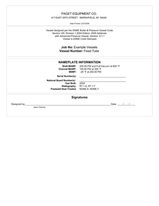
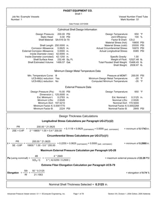
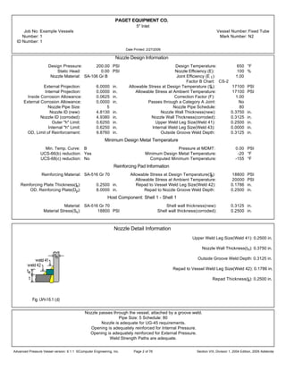
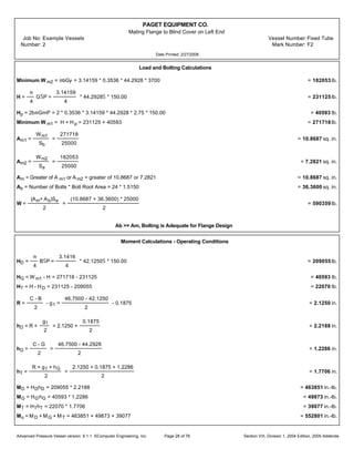
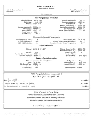
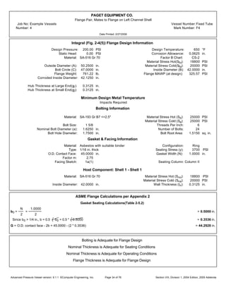
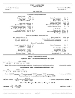
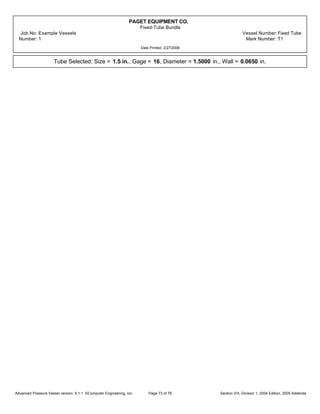
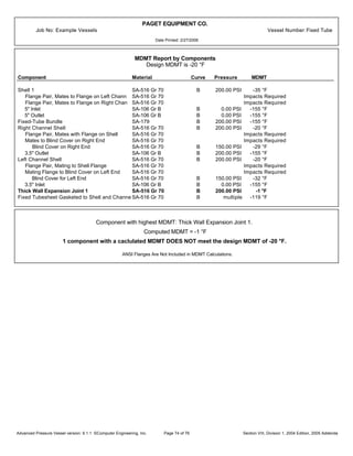
- Detailed calculations for the cylindrical shell and a 5" inlet nozzle to verify thickness and stress requirements are met.
- The nozzle is adequately reinforced for internal and external pressure loading based on area calculations.


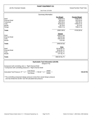
![PAGET EQUIPMENT CO.
5" Inlet
Job No: Example Vessels Vessel Number:Fixed Tube
Number: 1 Mark Number: N2
ID Number: 1
Date Printed: 2/27/2006
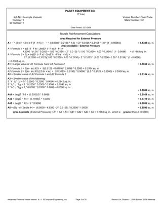
Nozzle Weld Strength Calculations
Attachment Weld Strength per Paragraph UW-16
Weld 41 tmin = smaller of 0.75, te, or tn = smaller of 0.75, 0.2500, or 0.3125 = 0.2500 in.
Weld 41 Leg min. =
(smaller of 0.25 or (tmin * 0.7)) + ext. CA
0.7
=
0.1750
0.7
= 0.2500 in.
Weld 41, actual weld leg = 0.2500 in.
Weld 42 tmin = smaller of 0.75, t, or te = smaller of 0.75, 0.2500, or 0.2500 = 0.2500 in.
Weld 42 Leg min. =
0.5 * tmin + ext. CA
0.7
=
0.5 * 0.2500 + 0.0000
0.7
= 0.1786 in.
Weld 42, actual weld leg = 0.1786 in.
Unit Stresses per Paragraphs UG-45(c) and UW-15
Nozzle wall in shear = 0.70 * Sn = 0.70 * 17100 = 11970 PSI
Upper fillet, Weld 41, in shear = 0.49 * Material Stress = 0.49 * 17100 = 8379 PSI
Vessel groove weld, in tension = 0.74 * Material Stress = 0.74 * 17100 = 12654 PSI
Outer fillet, Weld 42, in shear = 0.49 * Material Stress = 0.49 * 18800 = 9212 PSI
Repad groove weld, in tension = 0.74 * Material Stress = 0.74 * 17100 = 12654 PSI
Strength of Connection Elements
Nozzle wall in shear = • * m * mean nozzle diameter * tn * Nozzle wall in shear unit stress =
• * m * 5.2505 * 0.3125 * 11970 = 30800 lb.
Upper fillet in shear = • * m * Nozzle OD * weld leg * upper fillet in shear unit stress= • * m * 5.5630 * 0.2500 * 8379 = 18300 lb.
Groove Weld in Tension = • * m * Nozzle OD * groove depth * groove weld tension unit stress =
• * m * 5.5630 * 0.2500 * 12654 = 27600 lb.
Outer fillet in shear = • * m * Plate OD * weld leg * outer fillet in shear unit stress= • * m * 8.0000 * 0.1786 * 9212 = 20700 lb.
Repad groove weld = • * m * Nozzle OD * Groove Depth * repad groove weld in tension unit stress =
• * m * 5.5630 * 0.2500 * 12654 = 27600 lb.
Load to be carried by welds, per UG-41(b)(1) and Fig. UG-41.1 sketch (a)
W = [A - A1 + 2 tn fr1(E1t - Ftr)] Sv = [1.1263 - 0.1196 + 2 * 0.3125 * 0.9096 * (1.00 * 0.2500 - 1.0000 * 0.2255)] * 18800 = 19200 lb.
W1-1 = (A2 + A5 + A41 + A42) * Sv = (0.3222 + 0.6093 + 0.0568 + 0.0319) * 18800 = 19200 lb.
W2-2 = (A2 + A3 + A41 + A43 + 2 tn t fr1) Sv = (0.3222 + 0.0000 + 0.0568 + 0.0000 + 2 * 0.3125 * 0.2500 * 0.9096) * 18800 = 9800 lb.
W3-3 = (A2 + A3 + A5 + A41 + A42 + A43 + 2 tn t fr1) * Sv =
(0.3222 + 0.0000 + 0.6093 + 0.0568 + 0.0319 + 0.0000 + 2 * 0.3125 * 0.2500 * 0.9096) * 18800 = 21900 lb.
Check Strength Paths
Path 1-1 = Outer fillet in shear + Nozzle wall in shear = 20700 + 30800 = 51500 lb.
Path 2-2 = Upper fillet in shear + Repad groove weld + Groove weld in tension + Inner fillet in shear =
18300 + 27600 + 27600 + 0 = 73500 lb.
Path 3-3 = Outer fillet in shear + Inner fillet in shear + Groove weld in tension = 20700 + 0 + 27600 = 48300 lb.
Advanced Pressure Vessel version: 9.1.1 ©Computer Engineering, Inc. Section VIII, Division 1, 2004 Edition, 2005 AddendaPage 6 of 76](https://image.slidesharecdn.com/engineeringexamplecalculation-200316093317/85/Engineering-example-calculation-7-320.jpg)


![PAGET EQUIPMENT CO.
5" Outlet
Job No: Example Vessels Vessel Number:Fixed Tube
Number: 2 Mark Number: N2
ID Number: 2
Date Printed: 2/27/2006
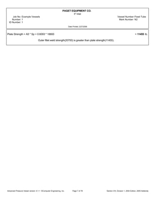
Nozzle Weld Strength Calculations
Attachment Weld Strength per Paragraph UW-16
Weld 41 tmin = smaller of 0.75, te, or tn = smaller of 0.75, 0.2500, or 0.3125 = 0.2500 in.
Weld 41 Leg min. =
(smaller of 0.25 or (tmin * 0.7)) + ext. CA
0.7
=
0.1750
0.7
= 0.2500 in.
Weld 41, actual weld leg = 0.2500 in.
Weld 42 tmin = smaller of 0.75, t, or te = smaller of 0.75, 0.2500, or 0.2500 = 0.2500 in.
Weld 42 Leg min. =
0.5 * tmin + ext. CA
0.7
=
0.5 * 0.2500 + 0.0000
0.7
= 0.1786 in.
Weld 42, actual weld leg = 0.1786 in.
Unit Stresses per Paragraphs UG-45(c) and UW-15
Nozzle wall in shear = 0.70 * Sn = 0.70 * 17100 = 11970 PSI
Upper fillet, Weld 41, in shear = 0.49 * Material Stress = 0.49 * 17100 = 8379 PSI
Vessel groove weld, in tension = 0.74 * Material Stress = 0.74 * 17100 = 12654 PSI
Outer fillet, Weld 42, in shear = 0.49 * Material Stress = 0.49 * 18800 = 9212 PSI
Repad groove weld, in tension = 0.74 * Material Stress = 0.74 * 17100 = 12654 PSI
Strength of Connection Elements
Nozzle wall in shear = • * m * mean nozzle diameter * tn * Nozzle wall in shear unit stress =
• * m * 5.2505 * 0.3125 * 11970 = 30800 lb.
Upper fillet in shear = • * m * Nozzle OD * weld leg * upper fillet in shear unit stress= • * m * 5.5630 * 0.2500 * 8379 = 18300 lb.
Groove Weld in Tension = • * m * Nozzle OD * groove depth * groove weld tension unit stress =
• * m * 5.5630 * 0.2500 * 12654 = 27600 lb.
Outer fillet in shear = • * m * Plate OD * weld leg * outer fillet in shear unit stress= • * m * 8.0000 * 0.1786 * 9212 = 20700 lb.
Repad groove weld = • * m * Nozzle OD * Groove Depth * repad groove weld in tension unit stress =
• * m * 5.5630 * 0.2500 * 12654 = 27600 lb.
Load to be carried by welds, per UG-41(b)(1) and Fig. UG-41.1 sketch (a)
W = [A - A1 + 2 tn fr1(E1t - Ftr)] Sv = [1.1263 - 0.1196 + 2 * 0.3125 * 0.9096 * (1.00 * 0.2500 - 1.0000 * 0.2255)] * 18800 = 19200 lb.
W1-1 = (A2 + A5 + A41 + A42) * Sv = (0.3222 + 0.6093 + 0.0568 + 0.0319) * 18800 = 19200 lb.
W2-2 = (A2 + A3 + A41 + A43 + 2 tn t fr1) Sv = (0.3222 + 0.0000 + 0.0568 + 0.0000 + 2 * 0.3125 * 0.2500 * 0.9096) * 18800 = 9800 lb.
W3-3 = (A2 + A3 + A5 + A41 + A42 + A43 + 2 tn t fr1) * Sv =
(0.3222 + 0.0000 + 0.6093 + 0.0568 + 0.0319 + 0.0000 + 2 * 0.3125 * 0.2500 * 0.9096) * 18800 = 21900 lb.
Check Strength Paths
Path 1-1 = Outer fillet in shear + Nozzle wall in shear = 20700 + 30800 = 51500 lb.
Path 2-2 = Upper fillet in shear + Repad groove weld + Groove weld in tension + Inner fillet in shear =
18300 + 27600 + 27600 + 0 = 73500 lb.
Path 3-3 = Outer fillet in shear + Inner fillet in shear + Groove weld in tension = 20700 + 0 + 27600 = 48300 lb.
Advanced Pressure Vessel version: 9.1.1 ©Computer Engineering, Inc. Section VIII, Division 1, 2004 Edition, 2005 AddendaPage 12 of 76](https://image.slidesharecdn.com/engineeringexamplecalculation-200316093317/85/Engineering-example-calculation-13-320.jpg)


![PAGET EQUIPMENT CO.
3.5" Inlet
Job No: Example Vessels Vessel Number:Fixed Tube
Number: 4 Mark Number: N5
ID Number: 4
Date Printed: 2/27/2006
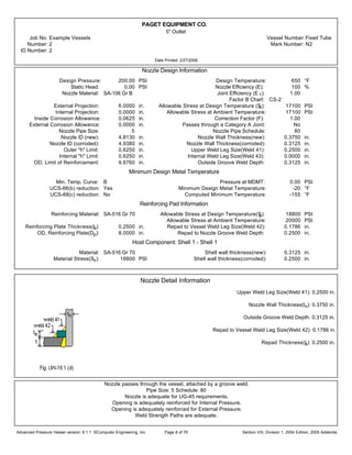
Nozzle Weld Strength Calculations
Attachment Weld Strength per Paragraph UW-16
Weld 41 tmin = smaller of 0.75, te, or tn = smaller of 0.75, 0.1875, or 0.2555 = 0.1875 in.
Weld 41 Leg min. =
(smaller of 0.25 or (tmin * 0.7)) + ext. CA
0.7
=
0.1313
0.7
= 0.1875 in.
Weld 41, actual weld leg = 0.1875 in.
Weld 42 tmin = smaller of 0.75, t, or te = smaller of 0.75, 0.1875, or 0.1875 = 0.1875 in.
Weld 42 Leg min. =
0.5 * tmin + ext. CA
0.7
=
0.5 * 0.1875 + 0.0000
0.7
= 0.1339 in.
Weld 42, actual weld leg = 0.1339 in.
Unit Stresses per Paragraphs UG-45(c) and UW-15
Nozzle wall in shear = 0.70 * Sn = 0.70 * 17100 = 11970 PSI
Upper fillet, Weld 41, in shear = 0.49 * Material Stress = 0.49 * 17100 = 8379 PSI
Vessel groove weld, in tension = 0.74 * Material Stress = 0.74 * 17100 = 12654 PSI
Outer fillet, Weld 42, in shear = 0.49 * Material Stress = 0.49 * 20000 = 9800 PSI
Repad groove weld, in tension = 0.74 * Material Stress = 0.74 * 17100 = 12654 PSI
Strength of Connection Elements
Nozzle wall in shear = • * m * mean nozzle diameter * tn * Nozzle wall in shear unit stress =
• * m * 3.7445 * 0.2555 * 11970 = 18000 lb.
Upper fillet in shear = • * m * Nozzle OD * weld leg * upper fillet in shear unit stress= • * m * 4.0000 * 0.1875 * 8379 = 9870 lb.
Groove Weld in Tension = • * m * Nozzle OD * groove depth * groove weld tension unit stress =
• * m * 4.0000 * 0.1875 * 12654 = 14900 lb.
Outer fillet in shear = • * m * Plate OD * weld leg * outer fillet in shear unit stress= • * m * 6.0000 * 0.1339 * 9800 = 12400 lb.
Repad groove weld = • * m * Nozzle OD * Groove Depth * repad groove weld in tension unit stress =
• * m * 4.0000 * 0.1875 * 12654 = 14900 lb.
Load to be carried by welds, per UG-41(b)(1) and Fig. UG-41.1 sketch (a)
W = [A - A1 + 2 tn fr1(E1t - Ftr)] Sv = [0.5655 - 0.0983 + 2 * 0.2555 * 0.8550 * (1.00 * 0.1875 - 1.0000 * 0.1587)] * 20000 = 9600 lb.
W1-1 = (A2 + A5 + A41 + A42) * Sv = (0.1925 + 0.3750 + 0.0301 + 0.0179) * 20000 = 12300 lb.
W2-2 = (A2 + A3 + A41 + A43 + 2 tn t fr1) Sv = (0.1925 + 0.0000 + 0.0301 + 0.0000 + 2 * 0.2555 * 0.1875 * 0.8550) * 20000 = 6090 lb.
W3-3 = (A2 + A3 + A5 + A41 + A42 + A43 + 2 tn t fr1) * Sv =
(0.1925 + 0.0000 + 0.3750 + 0.0301 + 0.0179 + 0.0000 + 2 * 0.2555 * 0.1875 * 0.8550) * 20000 = 13900 lb.
Check Strength Paths
Path 1-1 = Outer fillet in shear + Nozzle wall in shear = 12400 + 18000 = 30400 lb.
Path 2-2 = Upper fillet in shear + Repad groove weld + Groove weld in tension + Inner fillet in shear =
9870 + 14900 + 14900 + 0 = 39670 lb.
Path 3-3 = Outer fillet in shear + Inner fillet in shear + Groove weld in tension = 12400 + 0 + 14900 = 27300 lb.
Advanced Pressure Vessel version: 9.1.1 ©Computer Engineering, Inc. Section VIII, Division 1, 2004 Edition, 2005 AddendaPage 16 of 76](https://image.slidesharecdn.com/engineeringexamplecalculation-200316093317/85/Engineering-example-calculation-17-320.jpg)


![PAGET EQUIPMENT CO.
3.5" Outlet
Job No: Example Vessels Vessel Number:Fixed Tube
Number: 6 Mark Number: N3
ID Number: 6
Date Printed: 2/27/2006
Nozzle Weld Strength Calculations
Attachment Weld Strength per Paragraph UW-16
Weld 41 tmin = smaller of 0.75, te, or tn = smaller of 0.75, 0.1875, or 0.2555 = 0.1875 in.
Weld 41 Leg min. =
(smaller of 0.25 or (tmin * 0.7)) + ext. CA
0.7
=
0.1313
0.7
= 0.1875 in.
Weld 41, actual weld leg = 0.1875 in.
Weld 42 tmin = smaller of 0.75, t, or te = smaller of 0.75, 0.1875, or 0.1875 = 0.1875 in.
Weld 42 Leg min. =
0.5 * tmin + ext. CA
0.7
=
0.5 * 0.1875 + 0.0000
0.7
= 0.1339 in.
Weld 42, actual weld leg = 0.1339 in.
Unit Stresses per Paragraphs UG-45(c) and UW-15
Nozzle wall in shear = 0.70 * Sn = 0.70 * 17100 = 11970 PSI
Upper fillet, Weld 41, in shear = 0.49 * Material Stress = 0.49 * 17100 = 8379 PSI
Vessel groove weld, in tension = 0.74 * Material Stress = 0.74 * 17100 = 12654 PSI
Outer fillet, Weld 42, in shear = 0.49 * Material Stress = 0.49 * 20000 = 9800 PSI
Repad groove weld, in tension = 0.74 * Material Stress = 0.74 * 17100 = 12654 PSI
Strength of Connection Elements
Nozzle wall in shear = • * m * mean nozzle diameter * tn * Nozzle wall in shear unit stress =
• * m * 3.7445 * 0.2555 * 11970 = 18000 lb.
Upper fillet in shear = • * m * Nozzle OD * weld leg * upper fillet in shear unit stress= • * m * 4.0000 * 0.1875 * 8379 = 9870 lb.
Groove Weld in Tension = • * m * Nozzle OD * groove depth * groove weld tension unit stress =
• * m * 4.0000 * 0.1875 * 12654 = 14900 lb.
Outer fillet in shear = • * m * Plate OD * weld leg * outer fillet in shear unit stress= • * m * 6.0000 * 0.1339 * 9800 = 12400 lb.
Repad groove weld = • * m * Nozzle OD * Groove Depth * repad groove weld in tension unit stress =
• * m * 4.0000 * 0.1875 * 12654 = 14900 lb.
Load to be carried by welds, per UG-41(b)(1) and Fig. UG-41.1 sketch (a)
W = [A - A1 + 2 tn fr1(E1t - Ftr)] Sv = [0.5655 - 0.0983 + 2 * 0.2555 * 0.8550 * (1.00 * 0.1875 - 1.0000 * 0.1587)] * 20000 = 9600 lb.
W1-1 = (A2 + A5 + A41 + A42) * Sv = (0.1925 + 0.3750 + 0.0301 + 0.0179) * 20000 = 12300 lb.
W2-2 = (A2 + A3 + A41 + A43 + 2 tn t fr1) Sv = (0.1925 + 0.0000 + 0.0301 + 0.0000 + 2 * 0.2555 * 0.1875 * 0.8550) * 20000 = 6090 lb.
W3-3 = (A2 + A3 + A5 + A41 + A42 + A43 + 2 tn t fr1) * Sv =
(0.1925 + 0.0000 + 0.3750 + 0.0301 + 0.0179 + 0.0000 + 2 * 0.2555 * 0.1875 * 0.8550) * 20000 = 13900 lb.
Check Strength Paths
Path 1-1 = Outer fillet in shear + Nozzle wall in shear = 12400 + 18000 = 30400 lb.
Path 2-2 = Upper fillet in shear + Repad groove weld + Groove weld in tension + Inner fillet in shear =
9870 + 14900 + 14900 + 0 = 39670 lb.
Path 3-3 = Outer fillet in shear + Inner fillet in shear + Groove weld in tension = 12400 + 0 + 14900 = 27300 lb.
Advanced Pressure Vessel version: 9.1.1 ©Computer Engineering, Inc. Section VIII, Division 1, 2004 Edition, 2005 AddendaPage 20 of 76](https://image.slidesharecdn.com/engineeringexamplecalculation-200316093317/85/Engineering-example-calculation-21-320.jpg)


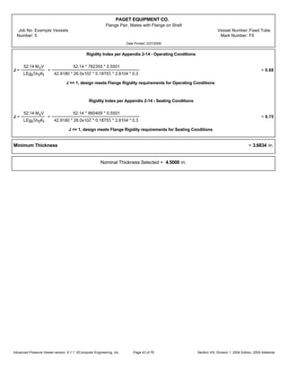
![PAGET EQUIPMENT CO.
Flange Pair, Mating to Shell Flange
Job No: Example Vessels Vessel Number:Fixed Tube
Number: 1 Mark Number: F1
Date Printed: 2/27/2006
Moment Calculations - Gasket Seating
Ms = Wh G = 635645 * 1.3536 = 860409 in.-lb.
Shape Constants
Calculated from Figure 2-7.1
K =
A
B
=
50.2500
42.1250
= 1.1929
Y =
1
K - 1
¥
¦
0.66845 + 5.71690
KŠlog10K
KŠ - 1
§
¨
=
1
1.1929 - 1
¥
¦
0.66845 +
¡
¢
5.7169 *
1.1929Š * log101.1929
1.1929Š - 1
£
¤
§
¨
= 11.1025
T =
KŠ(1 + 8.55246 log10K) - 1
(1.04720 + 1.9448KŠ)(K - 1)
=
1.1929Š(1 + 8.55246 log101.1929) - 1
[1.04720 + (1.9448 * 1.1929Š) ] (1.1929 - 1)
= 1.8418
U =
KŠ(1 + 8.55246 log10K) - 1
1.36136(KŠ - 1)(K - 1)
=
1.1929Š[1 + (8.55246 * log101.1929) ] - 1
1.36136(1.1929Š - 1)(1.1929 - 1)
= 12.2005
Z =
KŠ + 1
KŠ - 1
=
1.1929Š + 1
1.1929Š - 1
= 5.7280
h0 = Bg0 = 42.1250 * 0.1875 = 2.8104 in.
h
h0
=
0.0000
2.8104
= 0.0000
g1
g0
=
0.1875
0.1875
= 1.0000
Calculated from equations from TABLE 2-7.1
F = 0.9089 V = 0.5501 f = 1.0000
d =
¥
¦
U
V
§
¨
h0g0Š =
12.2005
0.5501
* 2.8104 * 0.1875Š = 2.1913 in.‹
e =
F
h0
=
0.9089
2.8104
= 0.3234 in.-1
L =
te + 1
T
+
t‹
d
=
(4.2500 * 0.3234) + 1
1.8418
+
4.2500‹
2.1913
= 36.3212
Bolt Spacing Calculations
Cf = 1, Correction factor not applied.
Advanced Pressure Vessel version: 9.1.1 ©Computer Engineering, Inc. Section VIII, Division 1, 2004 Edition, 2005 AddendaPage 24 of 76](https://image.slidesharecdn.com/engineeringexamplecalculation-200316093317/85/Engineering-example-calculation-25-320.jpg)
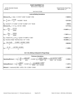
![PAGET EQUIPMENT CO.
Flange Pair, Mating to Shell Flange
Job No: Example Vessels Vessel Number:Fixed Tube
Number: 1 Mark Number: F1
Date Printed: 2/27/2006
Stress Calculations - Operating Conditions
SH =
fCfMo
Lg1ŠB
=
1.0000 * 1.0000 * 782355
36.3212 * 0.1875Š * 42.1250
= 14545 PSI
SR =
(˜ te + 1 ) C fMo
LtŠB
=
( ˜ * 4.2500 * 0.3234 + 1 ) * 1.0000 * 782355
36.3212 * 4.2500Š * 42.1250
= 80 PSI
ST =
Y Cf Mo
tŠB
- (Z S R) =
11.1025 * 1.0000 * 782355
4.2500Š * 42.1250
- ( 5.7280 * 80 ) = 10958 PSI
SH + SR
2
=
( 14545 + 80)
2
= 7313 PSI
SH + ST
2
=
( 14545 + 10958)
2
= 12752 PSI
Sc = Max
¥
¦
SH + SR
2
,
SH + ST
2
§
¨
= 12752 PSI SHmax = 1.5 Sfo = 1.5 * 18800 = 28200 PSI
Since (SH <= SHmax), (ST <= Sfo), (SR <= Sfo), ( Sc <= Sfo ), nominal thickness isADEQUATE for operating conditions
Stress Calculations - Gasket Seating
SH =
fCfMs
Lg1ŠB
=
1.0000 * 1.0000 * 860409
36.3212 * 0.1875Š * 42.1250
= 15996 PSI
SR =
(˜ te + 1) CfMs
L tŠ B
=
[(˜ * 4.2500 * 0.3234) + 1] * 1.0000 * 860409
36.3212 * 4.2500Š * 42.1250
= 88 PSI
ST =
Y Cf Ms
tŠ B
- (Z S R) =
11.1025 * 1.0000 * 860409
4.2500Š * 42.1250
- ( 5.7280 * 88) = 12051 PSI
SH + SR
2
=
15996 + 88
2
= 8042 PSI
SH + ST
2
=
15996 + 12051
2
= 14024 PSI
Sc = Max
¥
¦
SH + SR
2
,
SH + ST
2
§
¨
= 14024 PSI SHmax = 1.5 * S fa = 1.5 * 20000 = 30000 PSI
Since (SH <= SHmax), (SR <= Sfa), (ST <= Sfa), ( Sc <= Sfa ), nominal thickness isADEQUATE for seating conditions
Advanced Pressure Vessel version: 9.1.1 ©Computer Engineering, Inc. Section VIII, Division 1, 2004 Edition, 2005 AddendaPage 25 of 76](https://image.slidesharecdn.com/engineeringexamplecalculation-200316093317/85/Engineering-example-calculation-26-320.jpg)


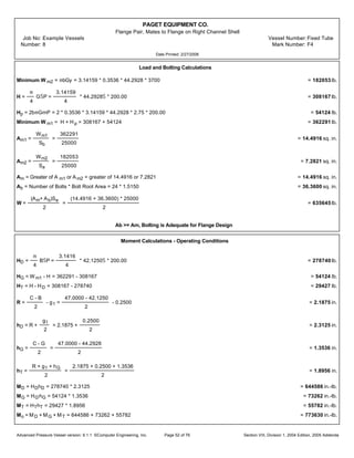
![PAGET EQUIPMENT CO.
Mating Flange to Blind Cover on Left End
Job No: Example Vessels Vessel Number:Fixed Tube
Number: 2 Mark Number: F2
Date Printed: 2/27/2006
Moment Calculations - Gasket Seating
Ms = Wh G = 590359 * 1.2286 = 725315 in.-lb.
Shape Constants
Calculated from Figure 2-7.1
K =
A
B
=
50.0000
42.1250
= 1.1869
Y =
1
K - 1
¥
¦
0.66845 + 5.71690
KŠlog10K
KŠ - 1
§
¨
=
1
1.1869 - 1
¥
¦
0.66845 +
¡
¢
5.7169 *
1.1869Š * log101.1869
1.1869Š - 1
£
¤
§
¨
= 11.4216
T =
KŠ(1 + 8.55246 log10K) - 1
(1.04720 + 1.9448KŠ)(K - 1)
=
1.1869Š(1 + 8.55246 log101.1869) - 1
[1.04720 + (1.9448 * 1.1869Š) ] (1.1869 - 1)
= 1.8442
U =
KŠ(1 + 8.55246 log10K) - 1
1.36136(KŠ - 1)(K - 1)
=
1.1869Š[1 + (8.55246 * log101.1869) ] - 1
1.36136(1.1869Š - 1)(1.1869 - 1)
= 12.5512
Z =
KŠ + 1
KŠ - 1
=
1.1869Š + 1
1.1869Š - 1
= 5.8932
h0 = Bg0 = 42.1250 * 0.1875 = 2.8104 in.
h
h0
=
0.0000
2.8104
= 0.0000
g1
g0
=
0.1875
0.1875
= 1.0000
Calculated from equations from TABLE 2-7.1
F = 0.9089 V = 0.5501 f = 1.0000
d =
¥
¦
U
V
§
¨
h0g0Š =
12.5512
0.5501
* 2.8104 * 0.1875Š = 2.2543 in.‹
e =
F
h0
=
0.9089
2.8104
= 0.3234 in.-1
L =
te + 1
T
+
t‹
d
=
(4.0000 * 0.3234) + 1
1.8442
+
4.0000‹
2.2543
= 29.6339
Bolt Spacing Calculations
Cf = 1, Correction factor not applied.
Advanced Pressure Vessel version: 9.1.1 ©Computer Engineering, Inc. Section VIII, Division 1, 2004 Edition, 2005 AddendaPage 29 of 76](https://image.slidesharecdn.com/engineeringexamplecalculation-200316093317/85/Engineering-example-calculation-30-320.jpg)
![PAGET EQUIPMENT CO.
Mating Flange to Blind Cover on Left End
Job No: Example Vessels Vessel Number:Fixed Tube
Number: 2 Mark Number: F2
Date Printed: 2/27/2006
Stress Calculations - Operating Conditions
SH =
fCfMo
Lg1ŠB
=
1.0000 * 1.0000 * 552801
29.6339 * 0.1875Š * 42.1250
= 12596 PSI
SR =
(˜ te + 1 ) C fMo
LtŠB
=
( ˜ * 4.0000 * 0.3234 + 1 ) * 1.0000 * 552801
29.6339 * 4.0000Š * 42.1250
= 75 PSI
ST =
Y Cf Mo
tŠB
- (Z S R) =
11.4216 * 1.0000 * 552801
4.0000Š * 42.1250
- ( 5.8932 * 75 ) = 8926 PSI
SH + SR
2
=
( 12596 + 75)
2
= 6336 PSI
SH + ST
2
=
( 12596 + 8926)
2
= 10761 PSI
Sc = Max
¥
¦
SH + SR
2
,
SH + ST
2
§
¨
= 10761 PSI SHmax = 1.5 Sfo = 1.5 * 20000 = 30000 PSI
Since (SH <= SHmax), (ST <= Sfo), (SR <= Sfo), ( Sc <= Sfo ), nominal thickness isADEQUATE for operating conditions
Stress Calculations - Gasket Seating
SH =
fCfMs
Lg1ŠB
=
1.0000 * 1.0000 * 725315
29.6339 * 0.1875Š * 42.1250
= 16527 PSI
SR =
(˜ te + 1) CfMs
L tŠ B
=
[(˜ * 4.0000 * 0.3234) + 1] * 1.0000 * 725315
29.6339 * 4.0000Š * 42.1250
= 99 PSI
ST =
Y Cf Ms
tŠ B
- (Z S R) =
11.4216 * 1.0000 * 725315
4.0000Š * 42.1250
- ( 5.8932 * 99) = 11708 PSI
SH + SR
2
=
16527 + 99
2
= 8313 PSI
SH + ST
2
=
16527 + 11708
2
= 14118 PSI
Sc = Max
¥
¦
SH + SR
2
,
SH + ST
2
§
¨
= 14118 PSI SHmax = 1.5 * S fa = 1.5 * 20000 = 30000 PSI
Since (SH <= SHmax), (SR <= Sfa), (ST <= Sfa), ( Sc <= Sfa ), nominal thickness isADEQUATE for seating conditions
Advanced Pressure Vessel version: 9.1.1 ©Computer Engineering, Inc. Section VIII, Division 1, 2004 Edition, 2005 AddendaPage 30 of 76](https://image.slidesharecdn.com/engineeringexamplecalculation-200316093317/85/Engineering-example-calculation-31-320.jpg)


![PAGET EQUIPMENT CO.
Flange Pair, Mates to Flange on Left Channel Shell
Job No: Example Vessels Vessel Number:Fixed Tube
Number: 4 Mark Number: F4
Date Printed: 2/27/2006
Moment Calculations - Gasket Seating
Ms = Wh G = 635645 * 1.3536 = 860409 in.-lb.
Shape Constants
Calculated from Figure 2-7.1
K =
A
B
=
50.2500
42.1250
= 1.1929
Y =
1
K - 1
¥
¦
0.66845 + 5.71690
KŠlog10K
KŠ - 1
§
¨
=
1
1.1929 - 1
¥
¦
0.66845 +
¡
¢
5.7169 *
1.1929Š * log101.1929
1.1929Š - 1
£
¤
§
¨
= 11.1025
T =
KŠ(1 + 8.55246 log10K) - 1
(1.04720 + 1.9448KŠ)(K - 1)
=
1.1929Š(1 + 8.55246 log101.1929) - 1
[1.04720 + (1.9448 * 1.1929Š) ] (1.1929 - 1)
= 1.8418
U =
KŠ(1 + 8.55246 log10K) - 1
1.36136(KŠ - 1)(K - 1)
=
1.1929Š[1 + (8.55246 * log101.1929) ] - 1
1.36136(1.1929Š - 1)(1.1929 - 1)
= 12.2005
Z =
KŠ + 1
KŠ - 1
=
1.1929Š + 1
1.1929Š - 1
= 5.7280
h0 = Bg0 = 42.1250 * 0.2500 = 3.2452 in.
h
h0
=
0.0000
3.2452
= 0.0000
g1
g0
=
0.2500
0.2500
= 1.0000
Calculated from equations from TABLE 2-7.1
F = 0.9089 V = 0.5501 f = 1.0000
d =
¥
¦
U
V
§
¨
h0g0Š =
12.2005
0.5501
* 3.2452 * 0.2500Š = 4.4984 in.‹
e =
F
h0
=
0.9089
3.2452
= 0.2801 in.-1
L =
te + 1
T
+
t‹
d
=
(4.5000 * 0.2801) + 1
1.8418
+
4.5000‹
4.4984
= 21.4845
Bolt Spacing Calculations
Cf = 1, Correction factor not applied.
Advanced Pressure Vessel version: 9.1.1 ©Computer Engineering, Inc. Section VIII, Division 1, 2004 Edition, 2005 AddendaPage 36 of 76](https://image.slidesharecdn.com/engineeringexamplecalculation-200316093317/85/Engineering-example-calculation-37-320.jpg)
![PAGET EQUIPMENT CO.
Flange Pair, Mates to Flange on Left Channel Shell
Job No: Example Vessels Vessel Number:Fixed Tube
Number: 4 Mark Number: F4
Date Printed: 2/27/2006
Stress Calculations - Operating Conditions
SH =
fCfMo
Lg1ŠB
=
1.0000 * 1.0000 * 773630
21.4845 * 0.2500Š * 42.1250
= 13677 PSI
SR =
(˜ te + 1 ) C fMo
LtŠB
=
( ˜ * 4.5000 * 0.2801 + 1 ) * 1.0000 * 773630
21.4845 * 4.5000Š * 42.1250
= 113 PSI
ST =
Y Cf Mo
tŠB
- (Z S R) =
11.1025 * 1.0000 * 773630
4.5000Š * 42.1250
- ( 5.7280 * 113 ) = 9422 PSI
SH + SR
2
=
( 13677 + 113)
2
= 6895 PSI
SH + ST
2
=
( 13677 + 9422)
2
= 11550 PSI
Sc = Max
¥
¦
SH + SR
2
,
SH + ST
2
§
¨
= 11550 PSI SHmax = 1.5 Sfo = 1.5 * 18800 = 28200 PSI
Since (SH <= SHmax), (ST <= Sfo), (SR <= Sfo), ( Sc <= Sfo ), nominal thickness isADEQUATE for operating conditions
Stress Calculations - Gasket Seating
SH =
fCfMs
Lg1ŠB
=
1.0000 * 1.0000 * 860409
21.4845 * 0.2500Š * 42.1250
= 15211 PSI
SR =
(˜ te + 1) CfMs
L tŠ B
=
[(˜ * 4.5000 * 0.2801) + 1] * 1.0000 * 860409
21.4845 * 4.5000Š * 42.1250
= 126 PSI
ST =
Y Cf Ms
tŠ B
- (Z S R) =
11.1025 * 1.0000 * 860409
4.5000Š * 42.1250
- ( 5.7280 * 126) = 10477 PSI
SH + SR
2
=
15211 + 126
2
= 7669 PSI
SH + ST
2
=
15211 + 10477
2
= 12844 PSI
Sc = Max
¥
¦
SH + SR
2
,
SH + ST
2
§
¨
= 12844 PSI SHmax = 1.5 * S fa = 1.5 * 20000 = 30000 PSI
Since (SH <= SHmax), (SR <= Sfa), (ST <= Sfa), ( Sc <= Sfa ), nominal thickness isADEQUATE for seating conditions
Advanced Pressure Vessel version: 9.1.1 ©Computer Engineering, Inc. Section VIII, Division 1, 2004 Edition, 2005 AddendaPage 37 of 76](https://image.slidesharecdn.com/engineeringexamplecalculation-200316093317/85/Engineering-example-calculation-38-320.jpg)


![PAGET EQUIPMENT CO.
Flange Pair, Mates with Flange on Shell
Job No: Example Vessels Vessel Number:Fixed Tube
Number: 5 Mark Number: F5
Date Printed: 2/27/2006
Moment Calculations - Gasket Seating
Ms = Wh G = 635645 * 1.3536 = 860409 in.-lb.
Shape Constants
Calculated from Figure 2-7.1
K =
A
B
=
50.2500
42.1250
= 1.1929
Y =
1
K - 1
¥
¦
0.66845 + 5.71690
KŠlog10K
KŠ - 1
§
¨
=
1
1.1929 - 1
¥
¦
0.66845 +
¡
¢
5.7169 *
1.1929Š * log101.1929
1.1929Š - 1
£
¤
§
¨
= 11.1025
T =
KŠ(1 + 8.55246 log10K) - 1
(1.04720 + 1.9448KŠ)(K - 1)
=
1.1929Š(1 + 8.55246 log101.1929) - 1
[1.04720 + (1.9448 * 1.1929Š) ] (1.1929 - 1)
= 1.8418
U =
KŠ(1 + 8.55246 log10K) - 1
1.36136(KŠ - 1)(K - 1)
=
1.1929Š[1 + (8.55246 * log101.1929) ] - 1
1.36136(1.1929Š - 1)(1.1929 - 1)
= 12.2005
Z =
KŠ + 1
KŠ - 1
=
1.1929Š + 1
1.1929Š - 1
= 5.7280
h0 = Bg0 = 42.1250 * 0.1875 = 2.8104 in.
h
h0
=
0.0000
2.8104
= 0.0000
g1
g0
=
0.1875
0.1875
= 1.0000
Calculated from equations from TABLE 2-7.1
F = 0.9089 V = 0.5501 f = 1.0000
d =
¥
¦
U
V
§
¨
h0g0Š =
12.2005
0.5501
* 2.8104 * 0.1875Š = 2.1913 in.‹
e =
F
h0
=
0.9089
2.8104
= 0.3234 in.-1
L =
te + 1
T
+
t‹
d
=
(4.5000 * 0.3234) + 1
1.8418
+
4.5000‹
2.1913
= 42.9180
Bolt Spacing Calculations
Cf = 1, Correction factor not applied.
Advanced Pressure Vessel version: 9.1.1 ©Computer Engineering, Inc. Section VIII, Division 1, 2004 Edition, 2005 AddendaPage 41 of 76](https://image.slidesharecdn.com/engineeringexamplecalculation-200316093317/85/Engineering-example-calculation-42-320.jpg)
![PAGET EQUIPMENT CO.
Flange Pair, Mates with Flange on Shell
Job No: Example Vessels Vessel Number:Fixed Tube
Number: 5 Mark Number: F5
Date Printed: 2/27/2006
Stress Calculations - Operating Conditions
SH =
fCfMo
Lg1ŠB
=
1.0000 * 1.0000 * 782355
42.9180 * 0.1875Š * 42.1250
= 12309 PSI
SR =
(˜ te + 1 ) C fMo
LtŠB
=
( ˜ * 4.5000 * 0.3234 + 1 ) * 1.0000 * 782355
42.9180 * 4.5000Š * 42.1250
= 63 PSI
ST =
Y Cf Mo
tŠB
- (Z S R) =
11.1025 * 1.0000 * 782355
4.5000Š * 42.1250
- ( 5.7280 * 63 ) = 9822 PSI
SH + SR
2
=
( 12309 + 63)
2
= 6186 PSI
SH + ST
2
=
( 12309 + 9822)
2
= 11066 PSI
Sc = Max
¥
¦
SH + SR
2
,
SH + ST
2
§
¨
= 11066 PSI SHmax = 1.5 Sfo = 1.5 * 18800 = 28200 PSI
Since (SH <= SHmax), (ST <= Sfo), (SR <= Sfo), ( Sc <= Sfo ), nominal thickness isADEQUATE for operating conditions
Stress Calculations - Gasket Seating
SH =
fCfMs
Lg1ŠB
=
1.0000 * 1.0000 * 860409
42.9180 * 0.1875Š * 42.1250
= 13537 PSI
SR =
(˜ te + 1) CfMs
L tŠ B
=
[(˜ * 4.5000 * 0.3234) + 1] * 1.0000 * 860409
42.9180 * 4.5000Š * 42.1250
= 69 PSI
ST =
Y Cf Ms
tŠ B
- (Z S R) =
11.1025 * 1.0000 * 860409
4.5000Š * 42.1250
- ( 5.7280 * 69) = 10803 PSI
SH + SR
2
=
13537 + 69
2
= 6803 PSI
SH + ST
2
=
13537 + 10803
2
= 12170 PSI
Sc = Max
¥
¦
SH + SR
2
,
SH + ST
2
§
¨
= 12170 PSI SHmax = 1.5 * S fa = 1.5 * 20000 = 30000 PSI
Since (SH <= SHmax), (SR <= Sfa), (ST <= Sfa), ( Sc <= Sfa ), nominal thickness isADEQUATE for seating conditions
Advanced Pressure Vessel version: 9.1.1 ©Computer Engineering, Inc. Section VIII, Division 1, 2004 Edition, 2005 AddendaPage 42 of 76](https://image.slidesharecdn.com/engineeringexamplecalculation-200316093317/85/Engineering-example-calculation-43-320.jpg)


![PAGET EQUIPMENT CO.
Mates to Blind Cover on Right End
Job No: Example Vessels Vessel Number:Fixed Tube
Number: 6 Mark Number: F6
Date Printed: 2/27/2006
Moment Calculations - Gasket Seating
Ms = Wh G = 590359 * 1.2286 = 725315 in.-lb.
Shape Constants
Calculated from Figure 2-7.1
K =
A
B
=
50.0000
42.1250
= 1.1869
Y =
1
K - 1
¥
¦
0.66845 + 5.71690
KŠlog10K
KŠ - 1
§
¨
=
1
1.1869 - 1
¥
¦
0.66845 +
¡
¢
5.7169 *
1.1869Š * log101.1869
1.1869Š - 1
£
¤
§
¨
= 11.4216
T =
KŠ(1 + 8.55246 log10K) - 1
(1.04720 + 1.9448KŠ)(K - 1)
=
1.1869Š(1 + 8.55246 log101.1869) - 1
[1.04720 + (1.9448 * 1.1869Š) ] (1.1869 - 1)
= 1.8442
U =
KŠ(1 + 8.55246 log10K) - 1
1.36136(KŠ - 1)(K - 1)
=
1.1869Š[1 + (8.55246 * log101.1869) ] - 1
1.36136(1.1869Š - 1)(1.1869 - 1)
= 12.5512
Z =
KŠ + 1
KŠ - 1
=
1.1869Š + 1
1.1869Š - 1
= 5.8932
h0 = Bg0 = 42.1250 * 0.1875 = 2.8104 in.
h
h0
=
0.0000
2.8104
= 0.0000
g1
g0
=
0.1875
0.1875
= 1.0000
Calculated from equations from TABLE 2-7.1
F = 0.9089 V = 0.5501 f = 1.0000
d =
¥
¦
U
V
§
¨
h0g0Š =
12.5512
0.5501
* 2.8104 * 0.1875Š = 2.2543 in.‹
e =
F
h0
=
0.9089
2.8104
= 0.3234 in.-1
L =
te + 1
T
+
t‹
d
=
(4.0000 * 0.3234) + 1
1.8442
+
4.0000‹
2.2543
= 29.6339
Bolt Spacing Calculations
Cf = 1, Correction factor not applied.
Advanced Pressure Vessel version: 9.1.1 ©Computer Engineering, Inc. Section VIII, Division 1, 2004 Edition, 2005 AddendaPage 46 of 76](https://image.slidesharecdn.com/engineeringexamplecalculation-200316093317/85/Engineering-example-calculation-47-320.jpg)
![PAGET EQUIPMENT CO.
Mates to Blind Cover on Right End
Job No: Example Vessels Vessel Number:Fixed Tube
Number: 6 Mark Number: F6
Date Printed: 2/27/2006
Stress Calculations - Operating Conditions
SH =
fCfMo
Lg1ŠB
=
1.0000 * 1.0000 * 552801
29.6339 * 0.1875Š * 42.1250
= 12596 PSI
SR =
(˜ te + 1 ) C fMo
LtŠB
=
( ˜ * 4.0000 * 0.3234 + 1 ) * 1.0000 * 552801
29.6339 * 4.0000Š * 42.1250
= 75 PSI
ST =
Y Cf Mo
tŠB
- (Z S R) =
11.4216 * 1.0000 * 552801
4.0000Š * 42.1250
- ( 5.8932 * 75 ) = 8926 PSI
SH + SR
2
=
( 12596 + 75)
2
= 6336 PSI
SH + ST
2
=
( 12596 + 8926)
2
= 10761 PSI
Sc = Max
¥
¦
SH + SR
2
,
SH + ST
2
§
¨
= 10761 PSI SHmax = 1.5 Sfo = 1.5 * 20000 = 30000 PSI
Since (SH <= SHmax), (ST <= Sfo), (SR <= Sfo), ( Sc <= Sfo ), nominal thickness isADEQUATE for operating conditions
Stress Calculations - Gasket Seating
SH =
fCfMs
Lg1ŠB
=
1.0000 * 1.0000 * 725315
29.6339 * 0.1875Š * 42.1250
= 16527 PSI
SR =
(˜ te + 1) CfMs
L tŠ B
=
[(˜ * 4.0000 * 0.3234) + 1] * 1.0000 * 725315
29.6339 * 4.0000Š * 42.1250
= 99 PSI
ST =
Y Cf Ms
tŠ B
- (Z S R) =
11.4216 * 1.0000 * 725315
4.0000Š * 42.1250
- ( 5.8932 * 99) = 11708 PSI
SH + SR
2
=
16527 + 99
2
= 8313 PSI
SH + ST
2
=
16527 + 11708
2
= 14118 PSI
Sc = Max
¥
¦
SH + SR
2
,
SH + ST
2
§
¨
= 14118 PSI SHmax = 1.5 * S fa = 1.5 * 20000 = 30000 PSI
Since (SH <= SHmax), (SR <= Sfa), (ST <= Sfa), ( Sc <= Sfa ), nominal thickness isADEQUATE for seating conditions
Advanced Pressure Vessel version: 9.1.1 ©Computer Engineering, Inc. Section VIII, Division 1, 2004 Edition, 2005 AddendaPage 47 of 76](https://image.slidesharecdn.com/engineeringexamplecalculation-200316093317/85/Engineering-example-calculation-48-320.jpg)


![PAGET EQUIPMENT CO.
Flange Pair, Mates to Flange on Right Channel Shell
Job No: Example Vessels Vessel Number:Fixed Tube
Number: 8 Mark Number: F4
Date Printed: 2/27/2006
Moment Calculations - Gasket Seating
Ms = Wh G = 635645 * 1.3536 = 860409 in.-lb.
Shape Constants
Calculated from Figure 2-7.1
K =
A
B
=
50.2500
42.1250
= 1.1929
Y =
1
K - 1
¥
¦
0.66845 + 5.71690
KŠlog10K
KŠ - 1
§
¨
=
1
1.1929 - 1
¥
¦
0.66845 +
¡
¢
5.7169 *
1.1929Š * log101.1929
1.1929Š - 1
£
¤
§
¨
= 11.1025
T =
KŠ(1 + 8.55246 log10K) - 1
(1.04720 + 1.9448KŠ)(K - 1)
=
1.1929Š(1 + 8.55246 log101.1929) - 1
[1.04720 + (1.9448 * 1.1929Š) ] (1.1929 - 1)
= 1.8418
U =
KŠ(1 + 8.55246 log10K) - 1
1.36136(KŠ - 1)(K - 1)
=
1.1929Š[1 + (8.55246 * log101.1929) ] - 1
1.36136(1.1929Š - 1)(1.1929 - 1)
= 12.2005
Z =
KŠ + 1
KŠ - 1
=
1.1929Š + 1
1.1929Š - 1
= 5.7280
h0 = Bg0 = 42.1250 * 0.2500 = 3.2452 in.
h
h0
=
0.0000
3.2452
= 0.0000
g1
g0
=
0.2500
0.2500
= 1.0000
Calculated from equations from TABLE 2-7.1
F = 0.9089 V = 0.5501 f = 1.0000
d =
¥
¦
U
V
§
¨
h0g0Š =
12.2005
0.5501
* 3.2452 * 0.2500Š = 4.4984 in.‹
e =
F
h0
=
0.9089
3.2452
= 0.2801 in.-1
L =
te + 1
T
+
t‹
d
=
(4.5400 * 0.2801) + 1
1.8418
+
4.5400‹
4.4984
= 22.0356
Bolt Spacing Calculations
Cf = 1, Correction factor not applied.
Advanced Pressure Vessel version: 9.1.1 ©Computer Engineering, Inc. Section VIII, Division 1, 2004 Edition, 2005 AddendaPage 53 of 76](https://image.slidesharecdn.com/engineeringexamplecalculation-200316093317/85/Engineering-example-calculation-54-320.jpg)
![PAGET EQUIPMENT CO.
Flange Pair, Mates to Flange on Right Channel Shell
Job No: Example Vessels Vessel Number:Fixed Tube
Number: 8 Mark Number: F4
Date Printed: 2/27/2006
Stress Calculations - Operating Conditions
SH =
fCfMo
Lg1ŠB
=
1.0000 * 1.0000 * 773630
22.0356 * 0.2500Š * 42.1250
= 13335 PSI
SR =
(˜ te + 1 ) C fMo
LtŠB
=
( ˜ * 4.5400 * 0.2801 + 1 ) * 1.0000 * 773630
22.0356 * 4.5400Š * 42.1250
= 109 PSI
ST =
Y Cf Mo
tŠB
- (Z S R) =
11.1025 * 1.0000 * 773630
4.5400Š * 42.1250
- ( 5.7280 * 109 ) = 9268 PSI
SH + SR
2
=
( 13335 + 109)
2
= 6722 PSI
SH + ST
2
=
( 13335 + 9268)
2
= 11302 PSI
Sc = Max
¥
¦
SH + SR
2
,
SH + ST
2
§
¨
= 11302 PSI SHmax = 1.5 Sfo = 1.5 * 18800 = 28200 PSI
Since (SH <= SHmax), (ST <= Sfo), (SR <= Sfo), ( Sc <= Sfo ), nominal thickness isADEQUATE for operating conditions
Stress Calculations - Gasket Seating
SH =
fCfMs
Lg1ŠB
=
1.0000 * 1.0000 * 860409
22.0356 * 0.2500Š * 42.1250
= 14831 PSI
SR =
(˜ te + 1) CfMs
L tŠ B
=
[(˜ * 4.5400 * 0.2801) + 1] * 1.0000 * 860409
22.0356 * 4.5400Š * 42.1250
= 121 PSI
ST =
Y Cf Ms
tŠ B
- (Z S R) =
11.1025 * 1.0000 * 860409
4.5400Š * 42.1250
- ( 5.7280 * 121) = 10309 PSI
SH + SR
2
=
14831 + 121
2
= 7476 PSI
SH + ST
2
=
14831 + 10309
2
= 12570 PSI
Sc = Max
¥
¦
SH + SR
2
,
SH + ST
2
§
¨
= 12570 PSI SHmax = 1.5 * S fa = 1.5 * 20000 = 30000 PSI
Since (SH <= SHmax), (SR <= Sfa), (ST <= Sfa), ( Sc <= Sfa ), nominal thickness isADEQUATE for seating conditions
Advanced Pressure Vessel version: 9.1.1 ©Computer Engineering, Inc. Section VIII, Division 1, 2004 Edition, 2005 AddendaPage 54 of 76](https://image.slidesharecdn.com/engineeringexamplecalculation-200316093317/85/Engineering-example-calculation-55-320.jpg)

![PAGET EQUIPMENT CO.
Fixed Tubesheet Gasketed to Shell and Channel
Job No: Example Vessels Vessel Number:Fixed Tube
Number: 1 Mark Number: FTS1
Date Printed: 2/27/2006
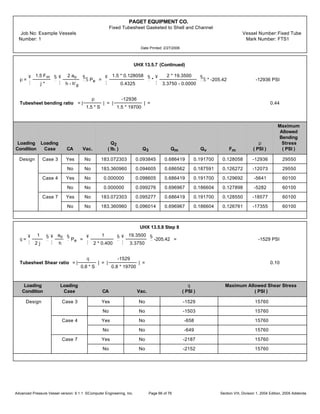
UHX 13.5 (Continued)
Loading Loading Sc Sy,c Ec Sts Sy,ts Ets
Condition Case Corroded (PSI) (PSI) (10Ž PSI) (PSI) (PSI) (10Ž PSI)
Design Case 7 No 20000 33050 28.1 19700 30050 26.9
SPS,s = 3 Ss = 3 * 18800 = 56400 PSI
SPS,c = 2 Sy,c = 2 * 33050 = 66100 PSI
SPS,ts = 2 Sy,ts = 2 * 30050 = 60100 PSI
UHX 13.5.1 Step 1
Determination of Effective Dimensions and Ligament Efficiencies per UHX 11.5.1
Do = 2 ro + dt = 2 * 18.6000 + 1.5000 = 38.7000 in.
j =
p - dt
p
=
2.5000 - 1.5000
2.5000
= 0.400
hg' = MAX [ h g - catsc, 0 ] = MAX [ 0.0000 - 0.0625 , 0 ] = 0.0000 in.
o =
{tx
h
=
3.2500
3.3750
= 1.0000
d* = MAX
¡
¢
¥
¦
dt - 2 tt
¥
¦
Et,ts
Ets
§
¨
¥
¦
St,ts
Sts
§
¨
o
§
¨
, ( dt - 2 tt )
£
¤
MAX
¡
¢
¥
¦
1.5000 - 2 * 0.0600
¥
¦
26.9 * 10Ž
26.9 * 10Ž
§
¨
¥
¦
13350
19700
§
¨
1.0000
§
¨
, ( 1.5000 - 2 * 0.0600 )
£
¤
= 1.4187 in.
p* =
p
¥
¦
1 -
4 MIN( A L, 4Dop )
mDoŠ
§
¨
•
=
2.5000
¥
¦
1 -
4 * Min(0.0000, 4 * 38.7000 * 2.5000 ),
m * 38.7000Š
§
¨
•
= 2.5000 in.
ao =
Do
2
=
38.7000
2
= 19.3500 in.
as =
Gs
2
=
44.2928
2
= 22.1464 in.
os =
as
ao
=
22.1464
19.3500
= 1.1445
ac =
Gc
2
=
44.2928
2
= 22.1464 in.
Advanced Pressure Vessel version: 9.1.1 ©Computer Engineering, Inc. Section VIII, Division 1, 2004 Edition, 2005 AddendaPage 60 of 76](https://image.slidesharecdn.com/engineeringexamplecalculation-200316093317/85/Engineering-example-calculation-61-320.jpg)
![PAGET EQUIPMENT CO.
Fixed Tubesheet Gasketed to Shell and Channel
Job No: Example Vessels Vessel Number:Fixed Tube
Number: 1 Mark Number: FTS1
Date Printed: 2/27/2006
UHX 13.5.2 (Continued)
ac = 0.000000000000 in.‹/lb.
UHX 13.5.3 Step 3
j* =
p* - d*
p*
=
2.5000 - 1.4187
2.5000
= 0.4325
Determination of Effective Elastic properites per UHX 11.5.2
h
p
=
3.3750
2.5000
= 1.3000
E*
Ets
= ^0 + ^1 j* + ^2 j*Š + ^3 j*‹ + ^4 j*Œ
14.0 * 10Ž
26.9 * 10Ž
= 0.0382 + 1.1579 * 0.4325 + -0.8567 * 0.4325Š + 2.7374 * 0.4325‹ + -2.2893 * 0.4325Œ = 0.5201
r* = _0 + _1 j* + _2 j*Š + _3 j*‹ + _4 j*Œ
0.3471 + -0.1611 * 0.4325 + 0.0972 * 0.4325 Š + 0.1432 * 0.4325‹ + -0.1293 * 0.4325Œ = 0.303
Xa =
¡
¢
24 ( 1 - r*Š ) Nt
Et tt ( dt - tt ) aoŠ
E* L h‹
£
¤
•
¡
¢
24 ( 1 - 0.303Š ) 400
28.1 * 10Ž * 0.0550 ( 1.4900 - 0.0550 ) 19.3500Š
14.0 * 10Ž * 243.3750 * 3.3750‹
£
¤
•
= 2.8049
Loading Loading
Condition Case CA Vac. ber bei ber' bei' v1 v2
Design Case 3 Yes No 0.058730 1.757546 -1.305587 0.957593 1.433116 -0.179226
No No 0.007637 1.794099 -1.355689 0.945930 1.461769 -0.224246
Case 4 Yes No 0.058730 1.757546 -1.305587 0.957593 1.433116 -0.179226
No No 0.007637 1.794099 -1.355689 0.945930 1.461769 -0.224246
Case 7 Yes No 0.058730 1.757546 -1.305587 0.957593 1.433116 -0.179226
No No 0.007637 1.794099 -1.355689 0.945930 1.461769 -0.224246
Za = bei' [ X a ] v2 [ X a ] - ber' [ X a ] v1 [ X a ]
0.957593 * ( -0.179226 ) - ( -1.305587 ) * 1.433116 = 1.699433
Zd =
ber [ Xa ] v2 [ X a ] + bei [ X a ] v1 [ X a ]
Xa‹ Za
0.058730 * ( -0.179226 ) + 1.757546 * 1.433116
2.8049‹ * 1.699433
= 0.066883
Advanced Pressure Vessel version: 9.1.1 ©Computer Engineering, Inc. Section VIII, Division 1, 2004 Edition, 2005 AddendaPage 62 of 76](https://image.slidesharecdn.com/engineeringexamplecalculation-200316093317/85/Engineering-example-calculation-63-320.jpg)
![PAGET EQUIPMENT CO.
Fixed Tubesheet Gasketed to Shell and Channel
Job No: Example Vessels Vessel Number:Fixed Tube
Number: 1 Mark Number: FTS1
Date Printed: 2/27/2006
UHX 13.5.3 (Continued)
Zv =
ber' [ X a ] v2 [ X a ] + bei' [ X a ] v1 [ X a ]
XaŠZa
=
( -1.305587 ) * ( -0.179226 ) + 0.957593 * 1.433116
2.8049Š * 1.699433
= 0.120143
Zm =
ber' [ X a ]Š + bei' [ x a ]Š
Xa Za
=
( -1.305587 )Š + 0.957593Š
2.8049 * 1.699433
= 0.549966
UHX 13.5.4 Step 4
K =
A
Do
=
45.0000
38.7000
= 1.1628
F =
1 - r*
E*
( is + ic + Ets ln K ) =
1 - 0.303
14.0 * 10Ž
( 0 + 0 + 26.9 * 10 Ž * ln 1.1628 ) = 0.2020
c = ( 1 + r* ) F = ( 1 + 0.303 ) 0.2020 = 0.2632
Q1 =
os - 1 - c Zv
1 + c Zm
=
1.1445 - 1 - 0.2632 * 0.120143
1 + 0.2632 * 0.549966
= 0.098605
QZ1 =
( Zd + Q1 Zv ) XaŒ
2
=
( 0.066883 + 0.098605 * 0.120143 ) 2.8049Œ
2
= 2.436566
QZ2 =
( Zv + Q1 Zm ) XaŒ
2
=
( 0.120143 + 0.098605 * 0.549966 ) 2.8049Œ
2
= 5.396563
U =
[ Zv + ( os - 1 ) Z m ] X aŒ
1 + c Zm
=
[ 0.120143 + ( 1.1445 - 1 ) 0.549966 ] 2.8049 Œ
1 + 0.2632 * 0.549966
= 10.793132
UHX 13.5.5 Step 5
ts = os ks _sas ( 1 + h _s ) = 1.1445 * 0 * 0.0000 * 0.000000000000 * ( 1 + 3.3750 * 0.0000 ) = 0.0000 sq. in.
ts* = aoŠ
( osŠ - 1 ) ( os - 1 )
4
- ts = 19.3500Š
( 1.1445Š - 1 ) * ( 1.1445 - 1 )
4
- 0.0000 = 4.1914 sq. in.
tc = oc kc _cac ( 1 + h _c ) = 1.1445 * 0 * 0.0000 * 0.000000000000 * ( 1 + 3.3750 * 0.0000 ) = 0.0000 sq. in.
tc* = aoŠ
¥
¦
( ocŠ + 1 ) ( oc - 1 )
4
-
( os - 1 )
2
§
¨
- tc =
19.3500Š
¥
¦
( 1.1445Š + 1 ) * ( 1.1445 - 1 )
4
-
( 1.1445 - 1 )
2
§
¨
- 0.0000 = 4.1914 sq. in.
Advanced Pressure Vessel version: 9.1.1 ©Computer Engineering, Inc. Section VIII, Division 1, 2004 Edition, 2005 AddendaPage 63 of 76](https://image.slidesharecdn.com/engineeringexamplecalculation-200316093317/85/Engineering-example-calculation-64-320.jpg)
![PAGET EQUIPMENT CO.
Fixed Tubesheet Gasketed to Shell and Channel
Job No: Example Vessels Vessel Number:Fixed Tube
Number: 1 Mark Number: FTS1
Date Printed: 2/27/2006
UHX 13.5.5 (Continued)
Loading Loading
Condition Case CA Vac. e
(in.)
Design Case 3 Yes No 0.0000
No No 0.0000
Case 4 Yes No -0.4053
No No -0.4051
Case 7 Yes No -0.4053
No No -0.4051
eb =
Gc - Gs
Do
=
44.2928 - 44.2928
38.7000
= 0.0000
Loading Loading Tr Ts* Tc* Ps* Pc*
Condition Case CA. Vac. (°F) (°F) (°F) (PSI) (PSI)
Design Case 3 Yes No NC NC NC NC NC
No No NC NC NC NC NC
Case 4 Yes No NC NC NC NC NC
No No NC NC NC NC NC
Case 7 Yes No NC NC NC NC NC
No No NC NC NC NC NC
UHX 13.5.6 Step 6
P's = {xs + 2 ( 1 - x s ) v t +
2
Ks,t
¥
¦
Ds
Do
§
¨
Š rs -
osŠ - 1
JKs,t
-
( 1 - J )
2 JKs,t
[ DJŠ - ( 2as ) Š ]
DoŠ
} Ps =
{ 0.4071 + 2 ( 1 - 0.4071 ) 0.310 +
2
0.3105
¥
¦
42.1250
38.7000
§
¨
Š 0.310 -
1.1445Š - 1
0.077812 * 0.3105
-
(1 - 0.077812 )
2 * 0.077812 * 0.3105
[ 48.0750Š - ( 2 * 22.1464 ) Š ]
38.7000Š
} 200.00 = -2827.39 PSI
P't =
¥
¦
xt + 2 ( 1 - x t ) v t +
1
JKs,t
§
¨
Pt =
¥
¦
0.4914 + 2 ( 1 - 0.4914 ) 0.310 +
1
0.077812 * 0.3105
§
¨
150.00 = 6329.46 PSI
Advanced Pressure Vessel version: 9.1.1 ©Computer Engineering, Inc. Section VIII, Division 1, 2004 Edition, 2005 AddendaPage 64 of 76](https://image.slidesharecdn.com/engineeringexamplecalculation-200316093317/85/Engineering-example-calculation-65-320.jpg)
![PAGET EQUIPMENT CO.
Fixed Tubesheet Gasketed to Shell and Channel
Job No: Example Vessels Vessel Number:Fixed Tube
Number: 1 Mark Number: FTS1
Date Printed: 2/27/2006
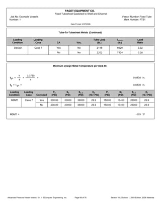
UHX 13.5.6 (Continued)
Pe =
NtKt
maoŠ
e =
400 * 28628
m * 19.3500Š
0.0000 = 0.00 PSI
PW = -
U
aoŠ
eb
2 m
W = -
10.793132
19.3500Š
*
0.0000
2 m
* 182053 = 0.00 PSI
Prim = -
U
aoŠ
( ts* Ps - tc* Pt ) = -
10.793132
19.3500Š
* ( 4.1914 * 200.00 - 4.1914 * 150.00 ) = -6.04 PSI
Pe =
JKs,t
1 + JKs,t [ Q Z1 + ( os - 1 ) Q Z2 ]
( P's - P't + Pe + PW + Prim ) =
0.077812 * 0.3105
1 + 0.077812 * 0.3105 [ 2.436566 + ( 1.1445 - 1 ) 5.396563 ]
* ( -2827.39 - 6329.46 + 0.00 + 0.00 + -6.04 ) =
-205.42 PSI
Loading Loading P's P't Pe Pt PW Prim Pe
Condition Case CA Vac. ( PSI ) ( PSI ) ( PSI ) ( PSI ) ( PSI ) ( PSI ) ( PSI )
Design Case 3 Yes No -2827.39 6329.46 0.00 NC 0.00 -6.04 -205.42
No No -3439.52 7349.37 0.00 NC 0.00 -6.29 -209.67
Case 4 Yes No 0.00 0.00 -3945.62 NC 0.00 0.00 -88.45
No No 0.00 0.00 -4663.18 NC 0.00 0.00 -90.57
Case 7 Yes No -2827.39 6329.46 -3945.62 NC 0.00 -6.04 -293.87
No No -3439.52 7349.37 -4663.18 NC 0.00 -6.29 -300.25
UHX 13.5.7 Step 7
Q2 =
( ts* Ps - tc* Pt ) +
eb
2 m
W
1 + C Zm
=
( 4.1914 * 200.00 - 4.1914 * 150.00 ) +
0.0000
2 * m
* 182053
1 + 0.2632 * 0.549966
=
183.072303 lb.
Q3 = Q1 +
2Q2
Pe aoŠ
= 0.098605 +
2 * 183.072303
-205.42 * 19.3500Š
= 0.093845
Advanced Pressure Vessel version: 9.1.1 ©Computer Engineering, Inc. Section VIII, Division 1, 2004 Edition, 2005 AddendaPage 65 of 76](https://image.slidesharecdn.com/engineeringexamplecalculation-200316093317/85/Engineering-example-calculation-66-320.jpg)
![PAGET EQUIPMENT CO.
Fixed Tubesheet Gasketed to Shell and Channel
Job No: Example Vessels Vessel Number:Fixed Tube
Number: 1 Mark Number: FTS1
Date Printed: 2/27/2006
UHX 13.5.9 Step 9
Fq =
( Zd + Q3 Zv ) XaŒ
2
=
( 0.066883 + 0.093845 * 0.120143 ) * 2.8049Œ
2
= 2.418867
pto =
( Ps xs - Pt xt ) - Pe Fq
xt - xs
=
( 200.00 * 0.4071 - 150.00 * 0.4914 ) - -205.42 * 2.418867
0.4914 - 0.4071
= 5986 PSI
Tube stress ratio = |
pto
St
| = |
5986
13400
| = 0.45
Maximum Allowable Maximum Allowable
Loading Loading Fq pto Axial Tube Stress Buckling Stress
Condition Case CA Vac. ( PSI ) ( PSI ) ( PSI )
Design Case 3 Yes No 2.418867 5986 13400 NC
No No 2.470042 5250 13400 NC
Case 4 Yes No 2.436566 2557 26800 NC
No No 2.488040 2262 26800 NC
Case 7 Yes No 2.424191 8542 26800 NC
No No 2.475471 7513 26800 NC
Tube-To-Tubesheet Welds per UW 20
Weld strength per UW 20.3
Sw = MIN [ S t,ts , Sts ] = MIN [ 13350 , 19700 ] = 13350 PSI
Weld strength factor per UW 20.3
fw =
St,ts
Sw
=
13350
13350
= 1.00
Tube strength factor per UW 20.3
Ft = tt m ( do - tt ) St,ts = 0.0550 * m ( 1.4900 - 0.0550 ) 13350 = 3310 lb.
Ratio of design strength to tube strength per UW 20.3
fd = 1.00
Groove Weld strength per UW 20.3
Fg = MIN [ ( 0.85 m ag ( do + 0.67 ag ) Sw ) , F t ] =
MIN [ ( 0.85 * m * 0.0625 ( 1.4900 + 0.67 * 0.0625 ) 13350 ) , 3310 ] = 3310 lb.
Advanced Pressure Vessel version: 9.1.1 ©Computer Engineering, Inc. Section VIII, Division 1, 2004 Edition, 2005 AddendaPage 67 of 76](https://image.slidesharecdn.com/engineeringexamplecalculation-200316093317/85/Engineering-example-calculation-68-320.jpg)
![PAGET EQUIPMENT CO.
Fixed Tubesheet Gasketed to Shell and Channel
Job No: Example Vessels Vessel Number:Fixed Tube
Number: 1 Mark Number: FTS1
Date Printed: 2/27/2006
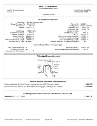
Tube-To-Tubesheet Welds (Continued)
Size of Tube-to-Tubesheet strength welds per UW 20.6(c)
ar = 2 [ ( 0.75 do )Š + 1.07 tt ( do - tt ) fw fd - 0.75 do ]
2 [ ( 0.75 * 1.4900 )Š + 1.07 * 0.0550 ( 1.4900 - 0.0550 ) 1.00 * 1.00 - 0.75 * 1.4900 ] = 0.0743 in.
Per UW 20.6(c) af = ag
ac = Max( a r, tt ) = Max( 0.0743, 0.0550 ) = 0.0743 in.
afr =
ac
2
=
0.0743
2
= 0.0372 in.
agr =
ac
2
=
0.0743
2
= 0.0372 in.
af ; afr = 0.0625 ; 0.0372 TRUE
ag ; agr = 0.0625 ; 0.0372 TRUE
Weld Image
Tube-To-Tubesheet Welds Summary
Tube Load = t t m ( do - tt ) |pt,o| = 0.0550 * m * ( 1.4900 - 0.0550 ) * |5986| = 1484 lb.
Lmax = Ft = 3310 lb.
Load Ratio = Tube Load / L max = 1484 / 3310 = 0.45
Loading Loading Tube Load Lmax Load
Condition Case CA Vac. (lb.) (lb.) Ratio
Design Case 3 Yes No 1484 3310 0.45
No No 1538 3912 0.39
Case 4 Yes No 634 6620 0.10
No No 663 7824 0.08
Advanced Pressure Vessel version: 9.1.1 ©Computer Engineering, Inc. Section VIII, Division 1, 2004 Edition, 2005 AddendaPage 68 of 76](https://image.slidesharecdn.com/engineeringexamplecalculation-200316093317/85/Engineering-example-calculation-69-320.jpg)

![Assignment [4] machining with solutions](https://cdn.slidesharecdn.com/ss_thumbnails/assignment4machining-withsolutions-121213110841-phpapp02-thumbnail.jpg?width=640&height=640&fit=bounds)


