Download to read offline


![Dosing Control Unit shares this information with the Powertrain Control Module over the J1939 Data Link.
Diesel exhaust fluid injection into the aftertreatment system is disabled.
WHEN MONITORED:
This monitor runs during normal operation when dosing is being commanded by the DEF Dosing Control Unit.
SET CONDITION:
The internal temperature of the DEF Dosing Control Unit is above 114°F [238°C] for more than five seconds.
POSSIBLE CAUSES
Always perform the Pre-Diagnostic Troubleshooting procedure before proceeding. Refer to PRE-
DIAGNOSTIC TROUBLESHOOTING PROCEDURE - 6.7L .
DIAGNOSTIC TEST
1. CHECK THE DEF DOSING CONTROL UNIT FOR PROPER MOUNTING
1. Visually inspect to ensure that the DEF Dosing Control Unit is mounted in the correct location on
the vehicle.
2. Check that all the fasteners are properly installed and secured.
Is the DEF Dosing Control Unit properly installed?
Yes
Go To 2.
No
Re-secure the DEF Dosing Control Unit properly.
Perform the POWERTRAIN VERIFICATION TEST - 6.7L. Refer to POWERTRAIN
VERIFICATION TEST - 6.7L .
2. CHECK FOR AN OBSTRUCTION OF AIRFLOW TO THE DEF DOSING CONTROL UNIT
1. Visually inspect for excessive debris on or around the DEF Dosing Control Unit.
Possible Causes
INADEQUATE AIRFLOW TO COOL THE DEF DOSING CONTROL UNIT
IMPROPER MOUNTING OF THE DEF DOSING CONTROL UNIT
DEF DOSING CONTROL UNIT
NOTE: Perform the diagnostics for this DTC regardless or whether code is active
or stored.
cardiagn.com](https://image.slidesharecdn.com/powertraincontrolmodule-pcm-electricaldiagnosti-230327065454-c8b4da05/75/Powertrain-Control-Module-PCM-Electrical-Diagnostics-764-2048.jpg)


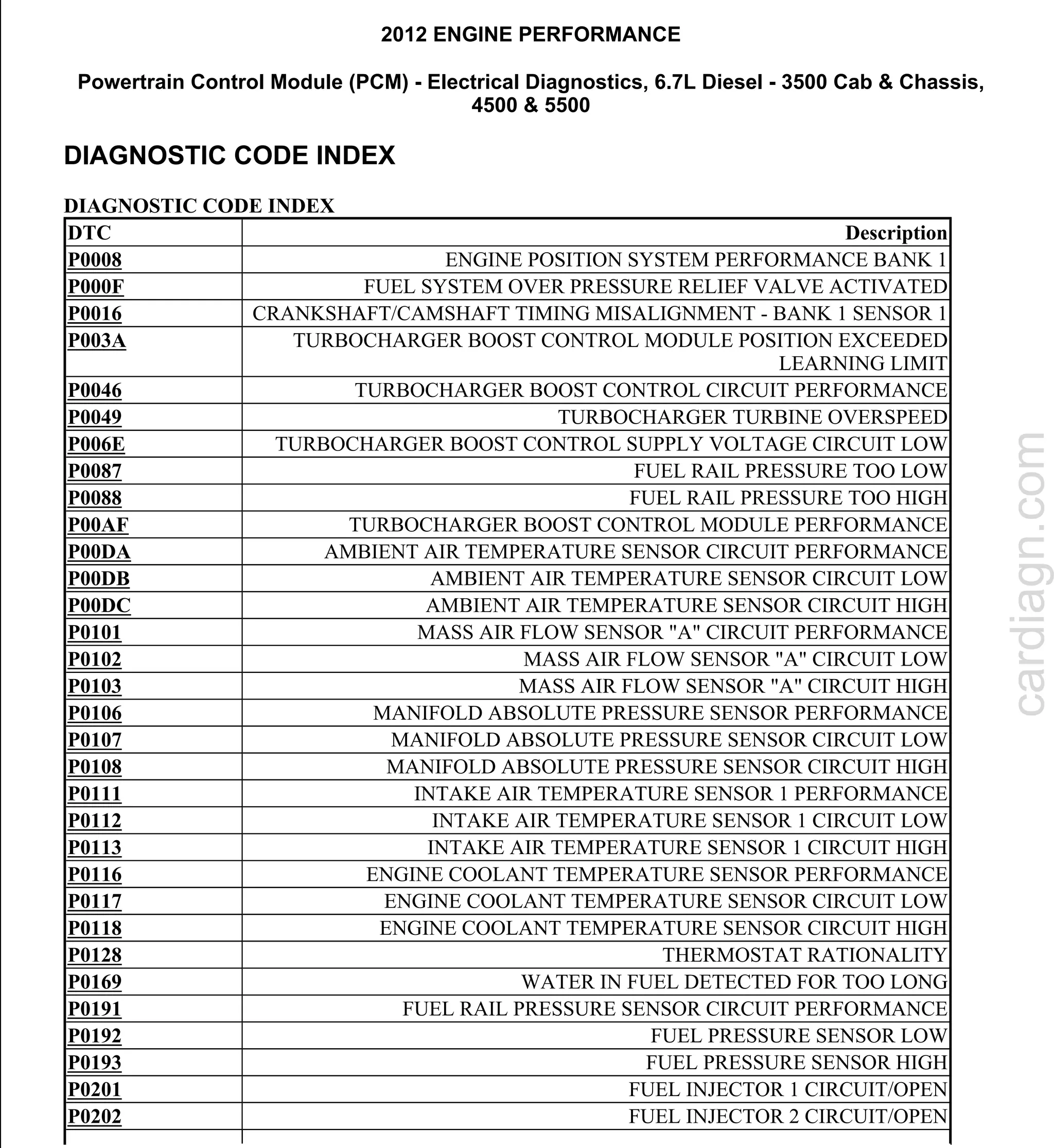
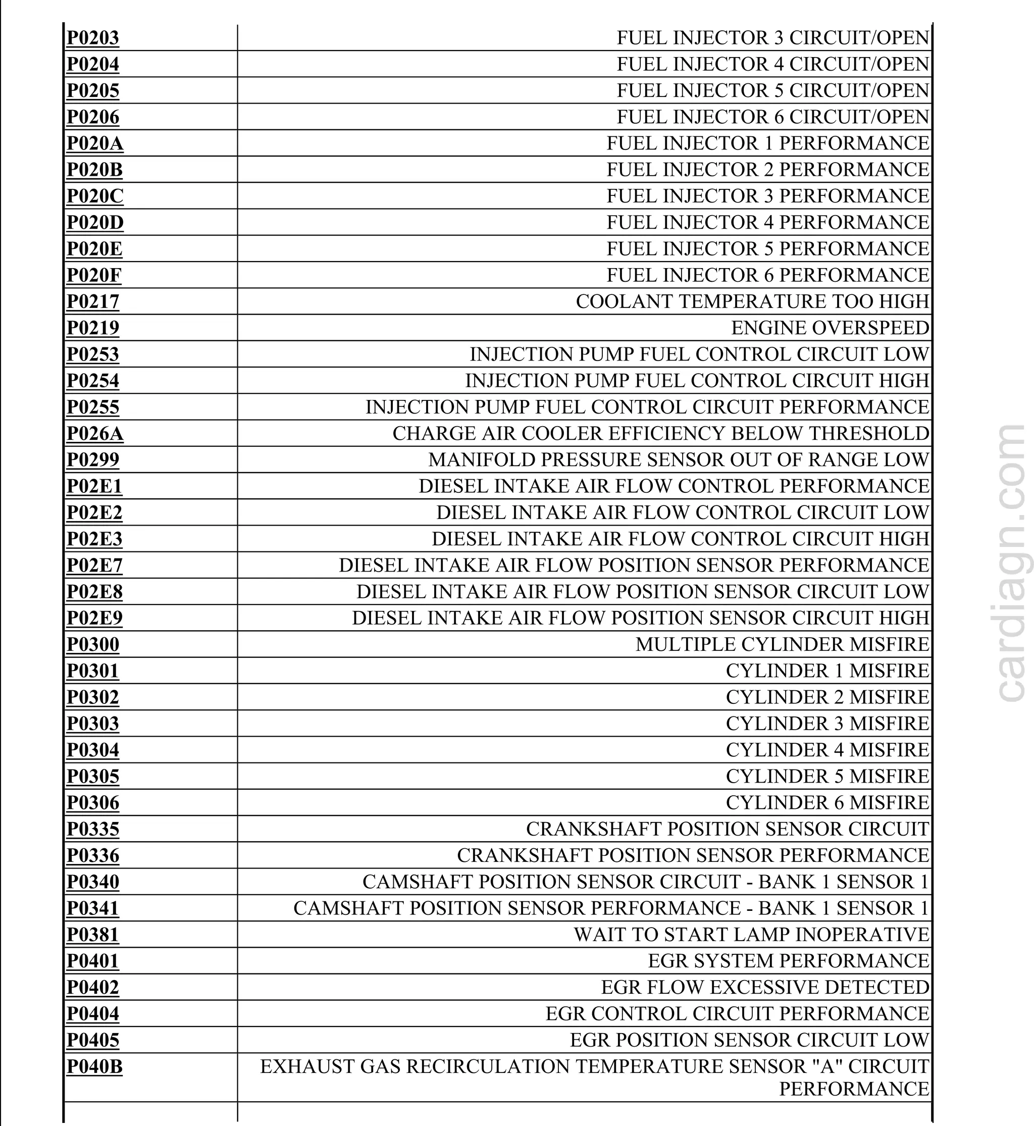
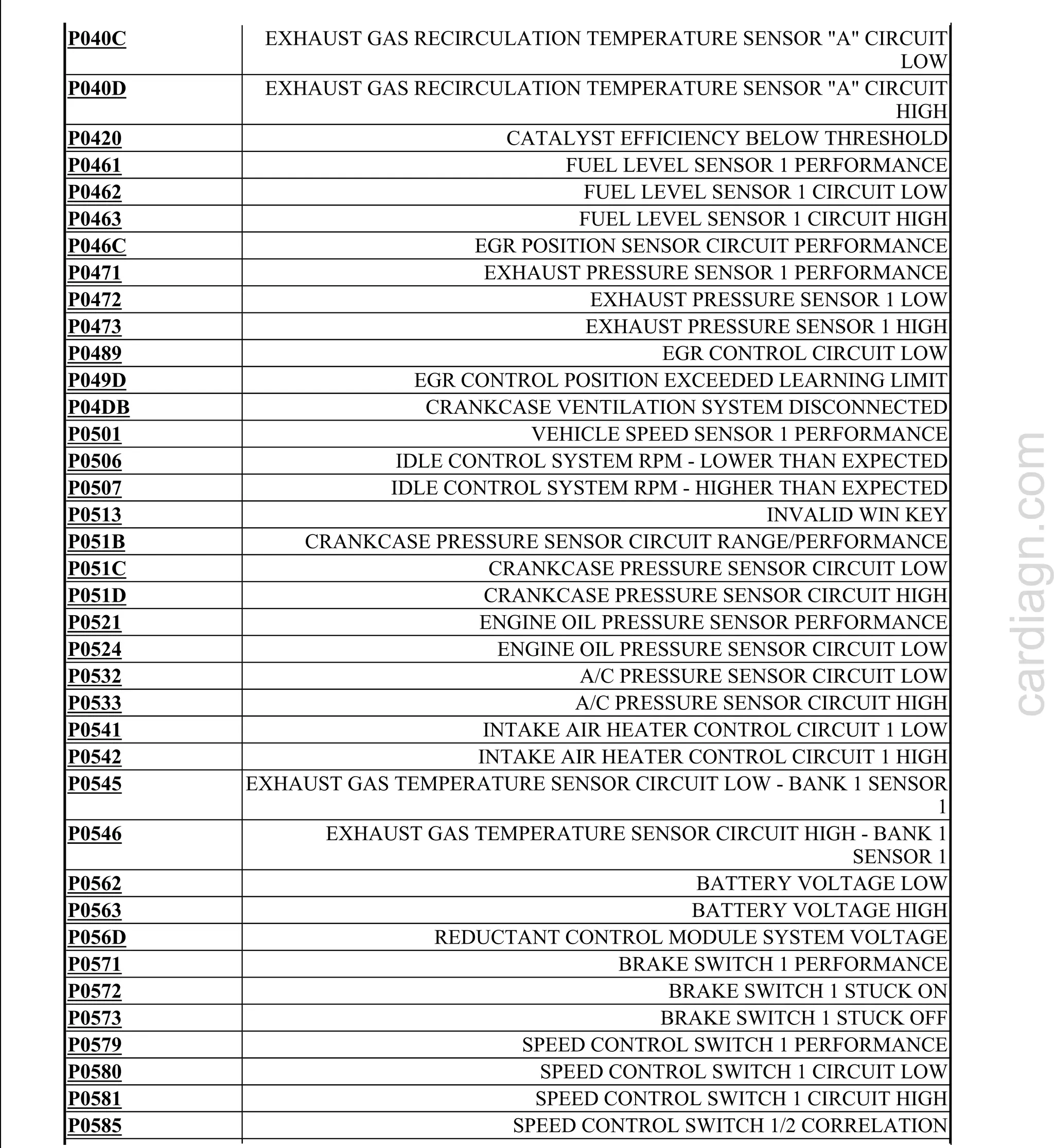
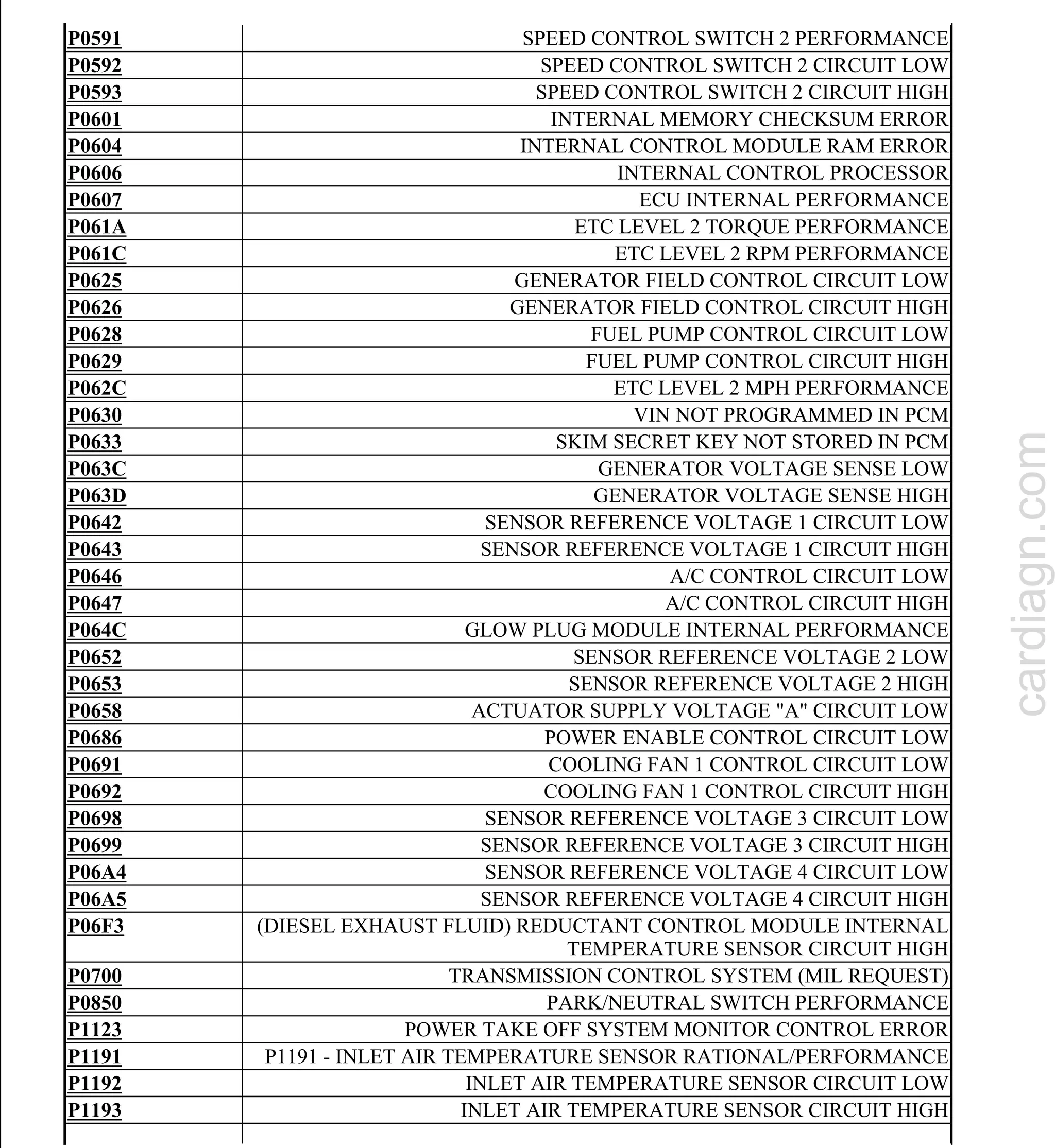
The document provides a comprehensive diagnostic code index for the 2012 engine performance powertrain control module (PCM) related to a 6.7L diesel engine used in 3500 cab & chassis, 4500, and 5500 models. It includes a detailed list of diagnostic trouble codes (DTCs) and their descriptions, highlighting various issues concerning engine performance and related systems such as fuel, turbocharger, and exhaust aftertreatment. The document also discusses the impacts of excess soot generated during the combustion process and its effects on downstream components in the exhaust and aftertreatment system.


