This document provides an overview and troubleshooting information for an engine control module (ECM) and ski control module (SKIM) system. It describes the functional operation of the ECM and SKIM, including on-board diagnostics, operating modes, and monitored circuits. The document outlines diagnostic trouble codes for each module, safety procedures, required tools, and provides detailed troubleshooting steps for various issues related to sensors, injectors, communication failures, and more.
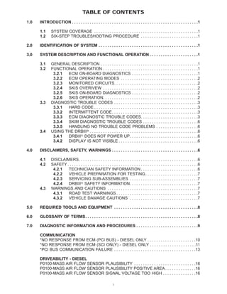


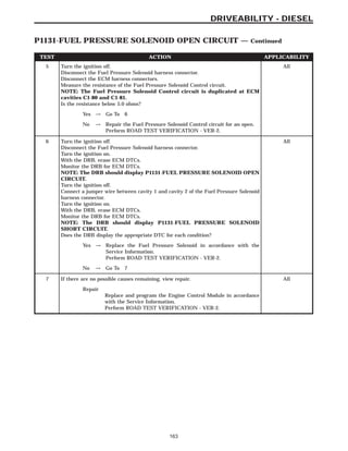


![TEST ACTION APPLICABILITY
2 Start and idle the engine.
With the DRBIII, select Instrument Cluster and read the PCM/ECM Monitors.
NOTE: If the DRB is unable to communicate with the Instrument cluster,
refer to the appropriate symptom in the Body Diagnostic Information
Does the DRB display accurate monitors?
All
Yes → [007f]Replace and program the Engine Control Module in accor-
dance with the Service Information.
Perform ROAD TEST VERIFICATION - VER-2.
No → Refer to Body Diagnostic Information for problems related to
Communication with ECM.
Perform ROAD TEST VERIFICATION - VER-2.
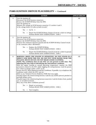
3 WARNING: WHEN THE ENGINE IS OPERATING, DO NOT STAND IN A
DIRECT LINE WITH THE FAN. DO NOT PUT YOUR HANDS NEAR THE
PULLEYS, BELTS OR FAN. DO NOT WEAR LOOSE CLOTHING.
NOTE: The conditions that set the DTC are not present at this time. The
following list may help in identifying the intermittent condition.
With the engine running at normal operating temperature, monitor the DRB
parameters related to the DTC while wiggling the wiring harness. Look for param-
eter values to change and/or a DTC to set.
Review the DTC When Monitored and Set Conditions. If possible, try to duplicate the
conditions under which the DTC was set.
Refer to any Technical Service Bulletins (TSB) that may apply.
Visually inspect the related wiring harness. Look for any chafed, pierced, pinched, or
partially broken wires.
Visually inspect the related wiring harness connectors. Look for broken, bent, pushed
out, or corroded terminals.
Were any of the above conditions present?
All
Yes → Repair as necessary.
Perform ROAD TEST VERIFICATION - VER-2.
No → Test Complete.
171
DRIVEABILITY - DIESEL
P1651-MIL/DIAG LAMP VIA J1850 BUS IN FRAME RESPONSE ERROR —
Continued](https://image.slidesharecdn.com/problemscode-170404170641/85/Problems-code-177-320.jpg)