This document provides information on the fuel system for a 2.5L diesel engine, including:
1) The fuel system consists of the fuel tank, fuel injection pump, fuel filter, fuel tank module, electrical components, fuel lines and injectors.
2) A separate fuel return system routes excess fuel from the injectors and injection pump back to the fuel tank.
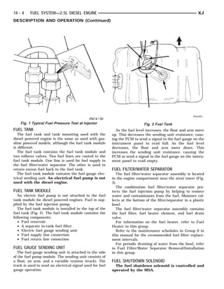
3) The fuel tank contains the fuel tank module which includes a fuel gauge sending unit. As the fuel level changes, the module sends signals to adjust the fuel gauge reading.