2. FUEL DELIVERY
DESCRIPTION
The fuel delivery system consists of:
• the 2–section fuel pump module containing the
electric fuel pump, fuel pressure regulator, fuel gauge
sending unit (fuel level sensor) and a fuel filter
located inside the lower section of pump module
• fuel tubes/lines/hoses
• A separately mounted main fuel filter
• quick-connect fittings
• fuel injector rail
• fuel tank
• fuel tank filler/vent tube assembly
• fuel tank filler tube cap
• accelerator pedal
• throttle cable
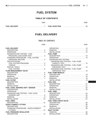
Certain fuel delivery components can be found in
(Fig. 1).
Fig. 1 FUEL DELIVERY COMPONENTS
1 - FUEL TANK 10 - EVAP CANISTER
2 - FUEL TANK STRAPS 11 - FLOW MANAGEMENT VALVE
3 - FUEL PUMP MODULE LOCK RING 12 - FRESH AIR TUBE
4 - CHECK (CONTROL) VALVE 13 - HOSE SLEEVE
5 - FUEL PUMP MODULE FLANGE 14 - FUEL FILTER
6 - FUEL FILL HOSE 15 - LEAK DETECTION PUMP
7 - FRESH AIR FILTER 16 - HEAT SHIELD
8 - FUEL FILL CAP/BEZEL 17 - SKID PLATE
9 - FUEL FILL TUBE
14 - 2 FUEL DELIVERY KJ
3. OPERATION
Fuel is picked up in the fuel tank by the fuel pump
module. This module is located on the bottom of the
fuel tank.
A fuel return system is provided within the fuel
pump module using check valves. A separate fuel
return line from the engine to the tank is not used.
The fuel pressure regulator and the main fuel filter
are not combined. They are separate items.
The fuel tank assembly consists of: the fuel tank,
fuel pump module assembly, fuel pump module lock
ring/gasket, ORVR components. Refer to 25, Emis-
sion Control System for ORVR information.
A fuel filler/vent tube assembly using a pressure/
vacuum, 1/4 turn fuel filler cap is used. The fuel
filler tube contains a flap door located below the fuel
fill cap. A one-way check valve is installed into the
tanks fuel fill fitting.
Also to be considered part of the fuel system is the
evaporation control system and ORVR system. This
is designed to reduce the emission of fuel vapors into
the atmosphere. The description and function of the
Evaporative Control System is found in 25, Emission
Control Systems.
Both fuel filters (mounted to front of fuel tank, and
inside the bottom fuel pump module) are designed for
extended service. They do not require normal sched-
uled maintenance. The bottom section of the fuel
pump module (with included filter) should only be
replaced if a diagnostic procedure indicates to do so.
Also, the fuel filter mounted to the front of the fuel
tank should only be replaced if a diagnostic proce-
dure indicates to do so.
DIAGNOSIS AND TESTING - FUEL PRESSURE
LEAK DOWN TEST
Use this test in conjunction with the Fuel Pump
Pressure Test and Fuel Pump Capacity Test.
Check Valve Operation: The electric fuel pump
outlet contains a one-way check valve to prevent fuel
flow back into the tank and to maintain fuel supply
line pressure (engine warm) when pump is not oper-
ational. It is also used to keep the fuel supply line
full of gasoline when pump is not operational. After
the vehicle has cooled down, fuel pressure may drop
to 0 psi (cold fluid contracts), but liquid gasoline will
remain in fuel supply line between the check valve
and fuel injectors. Fuel pressure that has
dropped to 0 psi on a cooled down vehicle
(engine off) is a normal condition. When the elec-
tric fuel pump is activated, fuel pressure should
immediately (1–2 seconds) rise to specification.
Abnormally long periods of cranking to restart a
hot engine that has been shut down for a short
period of time may be caused by:
• Fuel pressure bleeding past a fuel injector(s).
• Fuel pressure bleeding past the check valve in
the fuel pump module.
(1) Disconnect the fuel inlet line at fuel rail. Refer
to Quick Connect Fittings for procedures. On some
engines, air cleaner housing removal may be neces-
sary before fuel line disconnection.
(2) Obtain correct Fuel Line Pressure Test Adapter
Tool Hose. Tool number 6539 is used for 5/16” fuel
lines and tool number 6631 is used for 3/8” fuel lines.
(3) Connect correct Fuel Line Pressure Test
Adapter Tool Hose between disconnected fuel line
and fuel rail (Fig. 2).
(4) Connect the 0-414 kPa (0-60 psi) fuel pressure
test gauge (from Gauge Set 5069) to the test port on
the appropriate Adaptor Tool. The DRB III Scan
Tool along with the PEP module, the 500 psi
pressure transducer, and the transducer-to-test
port adapter may also be used in place of the
fuel pressure gauge.
The fittings on both tools must be in good
condition and free from any small leaks before
performing the proceeding test.
(5) Start engine and bring to normal operating
temperature.
(6) Observe test gauge. Normal operating pressure
should be 339 kPa +/–34 kPa (49.2 psi +/–5 psi).
(7) Shut engine off.
Fig. 2 CONNECTING ADAPTER TOOL—TYPICAL
1 - VEHICLE FUEL LINE
2 - TEST PORT “T”
3 - SPECIAL TOOL 6923, 6631, 6541 OR 6539
4 - FUEL PRESSURE TEST GAUGE
5 - FUEL LINE CONNECTION AT RAIL
6 - FUEL RAIL
KJ FUEL DELIVERY 14 - 3
FUEL DELIVERY (Continued)
4. (8) Pressure should not fall below 30 psi for five
minutes.
(9) If pressure falls below 30 psi, it must be deter-
mined if a fuel injector, the check valve within the
fuel pump module, or a fuel tube/line is leaking.
(10) Again, start engine and bring to normal oper-
ating temperature.
(11) Shut engine off.
(12) Testing for fuel injector or fuel rail leak-
age: Clamp off the rubber hose portion of Adaptor
Tool between the fuel rail and the test port “T” on
Adapter Tool. If pressure now holds at or above 30
psi, a fuel injector or the fuel rail is leaking.
(13) Testing for fuel pump check valve, filter,
regulator check valve or fuel tube/line leakage:
Clamp off the rubber hose portion of Adaptor Tool
between the vehicle fuel line and test port “T” on
Adapter Tool. If pressure now holds at or above 30
psi, a leak may be found at a fuel tube/line. If no
leaks are found at fuel tubes or lines, one of the
check valves in either the electric fuel pump, fuel fil-
ter or fuel pressure regulator may be leaking.
Note: A quick loss of pressure usually indicates a
defective check valve in the pressure regulator. A
slow loss of pressure usually indicates a defective
check valve in the bottom of the fuel pump module.
The check valves are not serviced separately. Also,
the electric fuel pump is not serviced separately.
STANDARD PROCEDURE - FUEL SYSTEM
PRESSURE RELEASE
Use following procedure if the fuel injector
rail is, or is not equipped with a fuel pressure
test port.
(1) Remove fuel fill cap.
(2) Remove fuel pump relay from Power Distribu-
tion Center (PDC). For location of relay, refer to label
on underside of PDC cover.
(3) Start and run engine until it stalls.
(4) Attempt restarting engine until it will no
longer run.
(5) Turn ignition key to OFF position.
CAUTION: Steps 1, 2, 3 and 4 must be performed to
relieve high pressure fuel from within fuel rail. Do
not attempt to use following steps to relieve this
pressure as excessive fuel will be forced into a cyl-
inder chamber.
(6) Unplug connector from any fuel injector.
(7) Attach one end of a jumper wire with alligator
clips (18 gauge or smaller) to either injector terminal.
(8) Connect other end of jumper wire to positive
side of battery.
(9) Connect one end of a second jumper wire to
remaining injector terminal.
CAUTION: Powering an injector for more than a few
seconds will permanently damage the injector.
(10) Momentarily touch other end of jumper wire
to negative terminal of battery for no more than a
few seconds.
(11) Place a rag or towel below fuel line quick-con-
nect fitting at fuel rail.
(12) Disconnect quick-connect fitting at fuel rail.
Refer to Quick-Connect Fittings.
(13) Return fuel pump relay to PDC.
(14) One or more Diagnostic Trouble Codes (DTC’s)
may have been stored in PCM memory due to fuel
pump relay removal. The DRB scan tool must be
used to erase a DTC.
14 - 4 FUEL DELIVERY KJ
FUEL DELIVERY (Continued)
6. SPECIAL TOOLS
FUEL SYSTEM
FLOW MANAGEMENT VALVE
DESCRIPTION
The flow management valve is a part of the ORVR
system. This plastic valve is placed inline between
the fuel tank vent fitting and the EVAP canister. It is
located on top of the fuel tank (Fig. 1).
OPERATION
The flow management valve (Fig. 1) is one of the com-
ponents used in the ORVR system. The valve meters
the flow of fuel vapors to the EVAP canister during
vehicle run and refueling. Pressure from the tank dur-
ing refueling opens the main port valve and allows
vapors to enter the EVAP canister. During vehicle run,
the vapors are metered through an orifice to the EVAP
canister. It is also used as a liquid separator to keep liq-
uid fuel out of the EVAP canister.
REMOVAL
The flow management valve is located on top of the
fuel tank (Fig. 1).
(1) Four cargo holdown clamps are located inside
the vehicle on the floor of the rear cargo area.
Remove the 2 rearward mounted clamps by drilling
out the clamp rivets.
(2) Fold carpeting forward to gain access to fuel
pump module access plate (Fig. 3).
Fig. 3 ACCESS PLATE
1 - FLOORPAN AT REAR
2 - FUEL PUMP MODULE ACCESS PLATE
3 - NUTS (4)
4 - OPENING TO PUMP MODULE
ADAPTERS, FUEL PRESSURE TEST—6539 AND/OR
6631
TEST KIT, FUEL PRESSURE—5069
TEST KIT, FUEL
14 - 6 FUEL DELIVERY KJ
FUEL DELIVERY (Continued)
7. (3) Remove 4 fuel pump module access plate nuts
(Fig. 3).
(4) While applying heat from a heat gun, carefully
pry up fuel pump module access plate. Take care not
to bend plate.
(5) Disconnect flow management valve hose clamp
and hose (Fig. 4) at pump module fitting. Also discon-
nect small recirculation line at top half of manage-
ment valve.
(6) Raise vehicle.
(7) Disconnect opposite end of flow management
valve hose at EVAP canister (Fig. 1).
(8) Remove valve and 2 hoses as an assembly.
INSTALLATION
(1) Raise vehicle.
(2) Attach 2 large hoses and 1 small line to flow
management valve. Position this assembly to top of
fuel tank.
(3) Connect valve hose at EVAP canister.
(4) Lower vehicle.
(5) Attach valve hose and clamp to top of fuel
pump module.
(6) Apply silicone sealant to bottom of fuel pump
module metal access plate.
(7) Install fuel pump module metal access plate
and 4 nuts. Tighten nuts to 3 N·m (26 in. lbs.)
torque.
(8) Position carpet and install 2 new cargo clamp
rivets.
FUEL FILTER
DESCRIPTION
The fuel pressure regulator and fuel filter are not
combined on this vehicle. The main fuel filter is
attached to the front of the fuel tank (Fig. 1) and is a
serviceable/replaceable item. Also refer to Inlet Filter
and Fuel Pressure Regulator.
REMOVAL
The main fuel filter is attached to the front of fuel
tank (Fig. 1). Three fuel lines are used at filter.
Fuel tank removal will not be necessary for
fuel filter removal. Access is from rear cargo
area.
WARNING: THE FUEL SYSTEM MAY BE UNDER A
CONSTANT PRESSURE (EVEN WITH THE ENGINE
OFF). BEFORE SERVICING MOST FUEL SYSTEM
COMPONENTS, THE FUEL SYSTEM PRESSURE
MUST BE RELEASED. REFER TO THE FUEL SYS-
TEM PRESSURE RELEASE PROCEDURE.
(1) Release fuel system pressure.
(2) Four cargo holdown clamps are located inside
vehicle on floor of rear cargo area. Two of these four
clamps must be removed. Remove 2 rearward
mounted clamps by drilling out clamp rivets.
(3) Fold carpeting forward to gain access to fuel
pump module access plate (Fig. 5).
(4) Remove 4 fuel pump module access plate nuts
(Fig. 5).
(5) While applying heat from a heat gun, carefully
pry up metal fuel pump module access plate. Take
care not to bend plate.
(6) Clean top of fuel pump module area around
fuel line connection points.
(7) Disconnect 2 fuel lines at fuel pump module
(Fig. 6) by pressing on tabs at side of fitting.
(8) Raise vehicle.
(9) Place drain pan under fuel filter.
(10) A third fuel line is attached to bottom of filter
(Fig. 7). The disconnection point for this 3rd line is
approximately 1 foot towards front of vehicle. Clean
fuel line connection point before disconnection. Dis-
connect by pressing on tabs at side of fitting.
(11) Disconnect 3rd fuel line from body retention
clip. Place a small screwdriver into side of clip and
twist for removal.
Fig. 4 TOP OF FUEL PUMP MODULE
1 - LOCK RING
2 - ALIGNMENT NOTCH
3 - FUEL FILTER FITTINGS (2)
4 - ORVR SYSTEM HOSE AND CLAMP
5 - FLOW MANAGEMENT VALVE
6 - ELECTRICAL CONNECTOR
7 - LEAK DETECTION PUMP
8 - FUEL TANK CHECK (CONTROL) VALVE
9 - FUEL PUMP MODULE (UPPER SECTION)
KJ FUEL DELIVERY 14 - 7
FLOW MANAGEMENT VALVE (Continued)
8. (12) Remove filter ground strap at fuel tank
mounting strap.
(13) Remove 1 filter mounting nut (Fig. 7) and
remove filter.
INSTALLATION
(1) Raise vehicle.
(2) Position fuel lines on filter towards top of fuel
tank.
(3) Position filter to mounting stud on front of fuel
tank.
(4) Install filter mounting nut and tighten. Refer
to torque specifications.
(5) A third fuel line is attached to bottom of filter.
The connection point for this 3rd line is approxi-
mately 1 foot towards front of vehicle. Connect by
snapping together.
(6) Connect 3rd fuel line to body retention clip
(snaps in).
(7) Attach filter ground strap to tank mounting
strap.
(8) Lower vehicle.
(9) Attach (snap on) 2 filter fuel lines at fuel pump
module fittings.
(10) Start engine and check fuel line fittings for
leaks.
(11) Apply silicone sealant to fuel pump module
metal access plate.
(12) Install fuel pump module metal access plate
and 4 nuts. Tighten 4 nuts. Refer to torque specifica-
tions.
(13) Position carpet and install 2 new cargo clamp
rivets in each cargo holdown clamp.
Fig. 5 ACCESS PLATE
1 - FLOORPAN AT REAR
2 - FUEL PUMP MODULE ACCESS PLATE
3 - NUTS (4)
4 - OPENING TO PUMP MODULE
Fig. 6 FUEL LINES AT PUMP MODULE
1 - FUEL PUMP MODULE LOCKRING
2 - FUEL LINES TO FUEL FILTER (2)
3 - QUICK-CONNECT FITTINGS (2)
4 - ROLLOVER VALVE
Fig. 7 FUEL FILTER LOCATION
1 - FUEL FILTER
2 - 3RD FUEL LINE TO ENGINE
3 - FILTER MOUNTING NUT
14 - 8 FUEL DELIVERY KJ
FUEL FILTER (Continued)
9. FUEL LEVEL SENDING UNIT /
SENSOR
DESCRIPTION
The fuel gauge sending unit (fuel level sensor) is
attached to the side of the fuel pump module. The
sending unit consists of a float, an arm, and a vari-
able resistor track (card).
OPERATION
The fuel pump module has 4 different circuits
(wires). Two of these circuits are used for the fuel
gauge sending unit for fuel gauge operation, and for
certain OBD II emission requirements. The other 2
wires are used for electric fuel pump operation.
For Fuel Gauge Operation: A constant current
source of approximately 32 milliamps is supplied to
the resistor track on the fuel gauge sending unit.
This is fed directly from the Powertrain Control Mod-
ule (PCM). NOTE: For diagnostic purposes, this
12V power source can only be verified with the
circuit opened (fuel pump module electrical
connector unplugged). With the connectors
plugged, output voltages will vary from about
0.6 volts at FULL, to about 8.6 volts at EMPTY
(about 8.6 volts at EMPTY for Jeep models, and
about 7.0 volts at EMPTY for Dodge Truck mod-
els). The resistor track is used to vary the voltage
(resistance) depending on fuel tank float level. As
fuel level increases, the float and arm move up,
which decreases voltage. As fuel level decreases, the
float and arm move down, which increases voltage.
The varied voltage signal is returned back to the
PCM through the sensor return circuit.
Both of the electrical circuits between the fuel
gauge sending unit and the PCM are hard-wired (not
multi-plexed). After the voltage signal is sent from
the resistor track, and back to the PCM, the PCM
will interpret the resistance (voltage) data and send
a message across the multi-plex bus circuits to the
instrument panel cluster. Here it is translated into
the appropriate fuel gauge level reading. Refer to
Instrument Panel for additional information.
For OBD II Emission Monitor Requirements:
The PCM will monitor the voltage output sent from
the resistor track on the sending unit to indicate fuel
level. The purpose of this feature is to prevent the
OBD II system from recording/setting false misfire
and fuel system monitor diagnostic trouble codes.
The feature is activated if the fuel level in the tank
is less than approximately 15 percent of its rated
capacity. If equipped with a Leak Detection Pump
(EVAP system monitor), this feature will also be acti-
vated if the fuel level in the tank is more than
approximately 85 percent of its rated capacity.
DIAGNOSIS AND TESTING - FUEL LEVEL
SENDING UNIT
The fuel level sending unit contains a variable
resistor (track). As the float moves up or down, elec-
trical resistance will change. Refer to Instrument
Panel and Gauges for Fuel Gauge testing. To test the
gauge sending unit only, it must be removed from
vehicle. The unit is a separate part of the lower fuel
pump module section. Refer to Fuel Pump Module
Removal/Installation for procedures (remove only the
upper section of the fuel pump module). Measure the
resistance across the sending unit terminals. With
float in up position, resistance should be 20 ohms (+/-
5%). With float in down position, resistance should be
270 ohms (+/- 5%).
REMOVAL
The fuel level sending unit (fuel level sensor) and
float assembly is located on the side of the lower sec-
tion of the fuel pump module. The lower section of
the fuel pump module is located within the fuel tank.
(1) Remove lower section of fuel pump module
from fuel tank. Refer to Fuel Pump Module Removal/
Installation.
(2) To remove sending unit from pump module, lift
on plastic locking tab (Fig. 8) while sliding sending
unit upwards.
(3) Disconnect 4–wire electrical connector (Fig. 9)
from bottom of upper section of fuel pump module.
Separate necessary sending unit wiring.
Fig. 8 FUEL LEVEL SENDING UNIT
1 - LIFT TAB HERE FOR REMOVAL
2 - FUEL LEVEL SENDING UNIT
3 - LOWER SECTION OF PUMP MODULE
KJ FUEL DELIVERY 14 - 9
10. INSTALLATION
(1) Connect necessary wiring into electrical con-
nectors. Connect 4–wire connector to upper section of
pump module.
(2) Position sending unit to pump module. Slide
and snap into place.
(3) Install lower section of fuel pump module.
Refer to Fuel Pump Module Removal/Installation.
FUEL LINES
DESCRIPTION
Also refer to Quick-Connect Fittings.
WARNING: THE FUEL SYSTEM MAY BE UNDER A
CONSTANT PRESSURE (EVEN WITH THE ENGINE
OFF). BEFORE SERVICING ANY FUEL SYSTEM
HOSES, FITTINGS, LINES, OR MOST COMPO-
NENTS, FUEL SYSTEM PRESSURE MUST BE
RELEASED. REFER TO THE FUEL SYSTEM PRES-
SURE RELEASE PROCEDURE.
The lines/tubes/hoses used on fuel injected vehicles
are of a special construction. This is due to the
higher fuel pressures and the possibility of contami-
nated fuel in this system. If it is necessary to replace
these lines/tubes/hoses, only those marked EFM/EFI
may be used.
If equipped: The hose clamps used to secure rub-
ber hoses on fuel injected vehicles are of a special
rolled edge construction. This construction is used to
prevent the edge of the clamp from cutting into the
hose. Only these rolled edge type clamps may be
used in this system. All other types of clamps may
cut into the hoses and cause high-pressure fuel leaks.
Use new original equipment type hose clamps.
QUICK CONNECT FITTING
DESCRIPTION
Different types of quick-connect fittings are used to
attach various fuel system components, lines and
tubes. These are: a single-tab type, a two-tab type or
a plastic retainer ring type. Some are equipped with
safety latch clips. Some may require the use of a spe-
cial tool for disconnection and removal. Refer to
Quick-Connect Fittings Removal/Installation for more
information.
CAUTION: The interior components (o-rings, clips)
of quick-connect fittings are not serviced sepa-
rately, but new plastic spacers are available for
some types. If service parts are not available, do
not attempt to repair the damaged fitting or fuel line
(tube). If repair is necessary, replace the complete
fuel line (tube) assembly.
STANDARD PROCEDURE - QUICK-CONNECT
FITTINGS
Also refer to Fuel Tubes/Lines/Hoses and Clamps.
Different types of quick-connect fittings are used to
attach various fuel system components, lines and
tubes. These are: a single-tab type, a two-tab type or
a plastic retainer ring type. Safety latch clips are
used on certain components/lines. Certain fittings
may require use of a special tool for disconnection.
DISCONNECTING
WARNING: THE FUEL SYSTEM IS UNDER A CON-
STANT PRESSURE (EVEN WITH ENGINE OFF).
BEFORE SERVICING ANY FUEL SYSTEM HOSE,
FITTING OR LINE, FUEL SYSTEM PRESSURE MUST
BE RELEASED. REFER TO FUEL SYSTEM PRES-
SURE RELEASE PROCEDURE.
Fig. 9 FUEL PRESSURE REGULATOR/SENDING
UNIT ELECTRICAL CONNECTOR
1 - UPPER SECTION OF PUMP MODULE
2 - QUICK-CONNECT FITTINGS
3 - FUEL PRESSURE REGULATOR
4 - 4-WIRE ELECTRICAL CONNECTOR
5 - FUEL TANK CHECK (CONTROL) VALVE
14 - 10 FUEL DELIVERY KJ
FUEL LEVEL SENDING UNIT / SENSOR (Continued)
11. CAUTION: The interior components (o-rings, spac-
ers) of some types of quick-connect fitting are not
serviced separately. If service parts are not avail-
able, do not attempt to repair a damaged fitting or
fuel line. If repair is necessary, replace complete
fuel line assembly.
(1) Perform fuel pressure release procedure. Refer
to Fuel Pressure Release Procedure.
(2) Disconnect negative battery cable from battery.
(3) Clean fitting of any foreign material before dis-
assembly.
(4) 2–Button Type Fitting: This type of fitting is
equipped with a push-button located on each side of
quick-connect fitting (Fig. 10). Press on both buttons
simultaneously for removal.
(5) Single-Tab Type Fitting: This type of fitting
is equipped with a single pull tab (Fig. 11). The tab is
removable. After tab is removed, quick-connect fitting
can be separated from fuel system component.
(a) Press release tab on side of fitting to release
pull tab (Fig. 12). If release tab is not pressed
prior to releasing pull tab, pull tab will be
damaged.
(b) While pressing release tab on side of fitting,
use screwdriver to pry up pull tab (Fig. 12).
(c) Raise pull tab until it separates from quick-
connect fitting (Fig. 13).
(6) Two-Tab Type Fitting: This type of fitting is
equipped with tabs located on both sides of fitting
(Fig. 14). The tabs are supplied for disconnecting
quick-connect fitting from component being serviced.
(a) To disconnect quick-connect fitting, squeeze
plastic retainer tabs (Fig. 14) against sides of
quick-connect fitting with your fingers. Tool use is
not required for removal and may damage plastic
retainer.
(b) Pull fitting from fuel system component
being serviced.
(c) The plastic retainer will remain on compo-
nent being serviced after fitting is disconnected.
The o-rings and spacer will remain in quick-con-
nect fitting connector body.
Fig. 10 2-BUTTON TYPE FITTING
1 - QUICK-CONNECT FITTING
2 - PUSH-BUTTONS (2)
Fig. 11 SINGLE-TAB TYPE FITTING
1 - PULL TAB
2 - QUICK-CONNECT FITTING
3 - PRESS HERE TO REMOVE PULL TAB
4 - INSERTED TUBE END
Fig. 12 DISCONNECTING SINGLE-TAB TYPE
FITTING
1 - PULL TAB
2 - SCREWDRIVER
3 - QUICK-CONNECT FITTING
KJ FUEL DELIVERY 14 - 11
QUICK CONNECT FITTING (Continued)
12. (7) Plastic Retainer Ring Type Fitting: This
type of fitting can be identified by the use of a full-
round plastic retainer ring (Fig. 15) usually black in
color.
(a) To release fuel system component from quick-
connect fitting, firmly push fitting towards compo-
nent being serviced while firmly pushing plastic
retainer ring into fitting (Fig. 15). With plastic ring
depressed, pull fitting from component. The plas-
tic retainer ring must be pressed squarely
into fitting body. If this retainer is cocked
during removal, it may be difficult to discon-
nect fitting. Use an open-end wrench on
shoulder of plastic retainer ring to aid in dis-
connection.
Fig. 13 REMOVING PULL TAB
1 - FUEL TUBE OR FUEL SYSTEM COMPONENT
2 - PULL TAB
3 - QUICK-CONNECT FITTING
4 - FUEL TUBE STOP
Fig. 14 TYPICAL 2–TAB TYPE FITTING
1 - TAB(S)
2 - QUICK-CONNECT FITTING
Fig. 15 PLASTIC RETAINER RING TYPE FITTING
1 - FUEL TUBE
2 - QUICK CONNECT FITTING
3 - PUSH
4 - PLASTIC RETAINER
5 - PUSH
6 - PUSH
7 - PUSH
8 - PUSH
Fig. 16 LATCH CLIP-TYPE 1
1 - TETHER STRAP
2 - FUEL LINE
3 - SCREWDRIVER
4 - LATCH CLIP
5 - FUEL RAIL
14 - 12 FUEL DELIVERY KJ
QUICK CONNECT FITTING (Continued)
13. (b) After disconnection, plastic retainer ring will
remain with quick-connect fitting connector body.
(c) Inspect fitting connector body, plastic retainer
ring and fuel system component for damage.
Replace as necessary.
(8) Latch Clips: Depending on vehicle model and
engine, 2 different types of safety latch clips are used
(Fig. 16) or (Fig. 17). Type-1 is tethered to fuel line
and type-2 is not. A special tool will be necessary to
disconnect fuel line after latch clip is removed. The
latch clip may be used on certain fuel line/fuel rail
connection, or to join fuel lines together.
(a) Type 1: Pry up on latch clip with a screw-
driver (Fig. 16).
(b) Type 2: Separate and unlatch 2 small arms
on end of clip (Fig. 17) and swing away from fuel
line.
(c) Slide latch clip toward fuel rail while lifting
with screwdriver.
(d) Insert special fuel line removal tool (Snap-On
number FIH 9055-1 or equivalent) into fuel line
(Fig. 18). Use tool to release locking fingers in end
of line.
(e) With special tool still inserted, pull fuel line
from fuel rail.
(f) After disconnection, locking fingers will
remain within quick-connect fitting at end of fuel
line.
(9) Disconnect quick-connect fitting from fuel sys-
tem component being serviced.
CONNECTING
(1) Inspect quick-connect fitting body and fuel sys-
tem component for damage. Replace as necessary.
(2) Prior to connecting quick-connect fitting to
component being serviced, check condition of fitting
and component. Clean parts with a lint-free cloth.
Lubricate with clean engine oil.
(3) Insert quick-connect fitting into fuel tube or
fuel system component until built-on stop on fuel
tube or component rests against back of fitting.
(4) Continue pushing until a click is felt.
(5) Single-tab type fitting: Push new tab down
until it locks into place in quick-connect fitting.
(6) Verify a locked condition by firmly pulling on
fuel tube and fitting (15-30 lbs.).
(7) Latch Clip Equipped: Install latch clip (snaps
into position). If latch clip will not fit, this indi-
cates fuel line is not properly installed to fuel
rail (or other fuel line). Recheck fuel line con-
nection.
(8) Connect negative cable to battery.
(9) Start engine and check for leaks.
FUEL PRESSURE REGULATOR
DESCRIPTION
The fuel pressure regulator is located on the bot-
tom of the upper section of the fuel pump module.
The fuel filter is not combined into the pressure
regulator on this model.
Fig. 17 LATCH CLIP-TYPE 2
1 - LATCH CLIP
Fig. 18 FUEL LINE DISCONNECTION USING
SPECIAL TOOL
1 - SPECIAL FUEL LINE TOOL
2 - FUEL LINE
3 - FUEL RAIL
KJ FUEL DELIVERY 14 - 13
QUICK CONNECT FITTING (Continued)
14. OPERATION
The fuel pressure regulator is a mechanical device
that is not controlled by engine vacuum or the Pow-
ertrain Control Module (PCM).
The regulator is calibrated to maintain fuel system
operating pressure of approximately 339 kPa +/- 34
kPa (49.2 psi +/- 5 psi) at the fuel injectors. It con-
tains a diaphragm, calibrated springs and a fuel
return valve.
The main fuel filter is not combined within the
fuel pressure regulator as in other Jeep models.
Three different fuel filters are used: 1. a serviceable,
separate, externally mounted, main fuel filter; 2. a
non-serviceable primary filter located on the bottom
of the electric fuel pump; 3. a non-serviceable second-
ary filter attached to the side of the fuel pump mod-
ule.
Fuel Flow: Fuel migrates into the fuel pump mod-
ule reservoir through a one-way check valve located
on the bottom of the module. This check valve pre-
vents the reservoir from running empty such as
when going up or down hills with a low amount of
fuel in the tank. A primary fuel filter (sock) is located
at the bottom of the electric fuel pump. Fuel is drawn
in through this filter, and up to the electric fuel
pump. High pressure fuel (unregulated) is supplied
from the electric fuel pump through a high-pressure
line to one of 3 fittings on the main fuel filter. If fuel
pressure at the pressure regulator exceeds approxi-
mately 49 psi, an internal diaphragm within the reg-
ulator closes, and excess fuel is routed through a
second fitting on the main fuel filter, and back into
the fuel tank (the fuel pressure regulator is installed
into the return side of the system). Pressure regu-
lated fuel is then delivered from the third fitting on
the fuel filter, up to and through the fuel rail, and on
to the fuel injectors.
A secondary fuel filter is attached to the side of the
fuel pump module. High-pressure from the electric
fuel pump causes a siphoning action across a passage
connected to this filter, and fuel is drawn into the
fuel pump module reservoir. This is used to help keep
the module reservoir full of fuel.
The fuel pressure regulator also acts as a check
valve to maintain some fuel pressure when the
engine is not operating. This will help to start the
engine. A second check valve is located at the outlet
of the fuel pump module housing. Refer to Fuel
Pump - Description and Operation for more
information. Also refer to the Fuel Pressure
Leak Down Test, and the Fuel Pump Pressure
Tests.
A separate fuel return line from the engine is not
used with this system.
REMOVAL
The fuel pressure regulator is located in the fuel
tank. It is attached to the bottom of the upper sec-
tion of the fuel pump module with a quick-connect
fitting (Fig. 19). The fuel pump module is supplied in
2 sections (upper and lower). To replace the pressure
regulator, the bottom section of the fuel pump mod-
ule must be replaced.
(1) Remove upper and lower sections of fuel pump
module from fuel tank. Refer to Fuel Pump Module
Removal/Installation.
(2) Replace lower section of fuel pump module
(includes fuel pressure regulator).
INSTALLATION
The fuel pressure regulator is located in the fuel
tank. It is attached to the bottom of the upper sec-
tion of the fuel pump module with a quick-connect
fitting. The fuel pump module is supplied in 2 sec-
tions (upper and lower). To replace the pressure reg-
ulator, the bottom section of the fuel pump module
must be replaced.
(1) Replace lower section of fuel pump module
(includes fuel pressure regulator).
(2) Install upper and lower sections of fuel pump
module to fuel tank. Refer to Fuel Pump Module
Installation.
Fig. 19 FUEL PRESSURE REGULATOR/SENDING
UNIT ELECTRICAL CONNECTOR
1 - UPPER SECTION OF PUMP MODULE
2 - QUICK-CONNECT FITTINGS
3 - FUEL PRESSURE REGULATOR
4 - 4-WIRE ELECTRICAL CONNECTOR
5 - FUEL TANK CHECK (CONTROL) VALVE
14 - 14 FUEL DELIVERY KJ
FUEL PRESSURE REGULATOR (Continued)
15. FUEL PUMP
DESCRIPTION
The electric fuel pump is located inside of the fuel
pump module. A 12 volt, permanent magnet, electric
motor powers the fuel pump. The electric fuel pump
is not a separate, serviceable component.
OPERATION
Voltage to operate the electric pump is supplied
through the fuel pump relay.
Fuel is drawn in through a filter at the bottom of
the module and pushed through the electric motor
gearset to the pump outlet.
Check Valve Operation: The bottom section of
the fuel pump module contains a one-way check
valve to prevent fuel flow back into the tank and to
maintain fuel supply line pressure (engine warm)
when pump is not operational. It is also used to keep
the fuel supply line full of gasoline when pump is not
operational. After the vehicle has cooled down, fuel
pressure may drop to 0 psi (cold fluid contracts), but
liquid gasoline will remain in fuel supply line
between the check valve and fuel injectors. Fuel
pressure that has dropped to 0 psi on a cooled
down vehicle (engine off) is a normal condition.
Refer to the Fuel Pressure Leak Down Test for more
information.
The electric fuel pump is not a separate, service-
able component.
DIAGNOSIS AND TESTING
DIAGNOSIS AND TESTING - FUEL PUMP
CAPACITY TEST
Before performing this test, verify fuel pump
pressure. Refer to Fuel Pump Pressure Test.
Use this test in conjunction with the Fuel Pres-
sure Leak Down Test.
(1) Release fuel system pressure. Refer to Fuel
Pressure Release Procedure.
(2) Disconnect fuel supply line at fuel rail. Refer to
Quick-Connect Fittings. Some engines may require
air cleaner housing removal before line disconnection.
(3) Obtain correct Fuel Line Pressure Test Adapter
Tool Hose. Tool number 6539 is used for 5/16” fuel
lines and tool number 6631 is used for 3/8” fuel lines.
(4) Connect correct Fuel Line Pressure Test
Adapter Tool Hose into disconnected fuel supply line.
Insert other end of Adaptor Tool Hose into a gradu-
ated container.
(5) Remove fuel fill cap.
(6) To activate fuel pump and pressurize system,
obtain DRB scan tool and actuate ASD Fuel System
Test.
(7) A good fuel pump will deliver at least 1/10 liter
of fuel in 7 seconds. Do not operate fuel pump for
longer than 7 seconds with fuel line disconnected as
fuel pump module reservoir may run empty.
(a) If capacity is lower than specification, but
fuel pump can be heard operating through fuel fill
cap opening, check for a kinked/damaged fuel sup-
ply line somewhere between fuel rail and fuel
pump module.
(b) If line is not kinked/damaged, and fuel pres-
sure is OK, but capacity is low, replace fuel filter.
Refer to Fuel Filter Removal/Installation for addi-
tional information.
(c) If both fuel pressure and capacity are low,
replace bottom section of fuel pump module. Refer
to Fuel Pump Module Removal/Installation.
DIAGNOSIS AND TESTING - FUEL PUMP
PRESSURE TEST
Use this test in conjunction with the Fuel Pump
Capacity Test, Fuel Pressure Leak Down Test and
Fuel Pump Amperage Test found elsewhere in this
group.
Check Valve Operation: The bottom section of
the fuel pump module contains a one-way check
valve to prevent fuel flow back into the tank and to
maintain fuel supply line pressure (engine warm)
when pump is not operational. It is also used to keep
the fuel supply line full of gasoline when pump is not
operational. After the vehicle has cooled down, fuel
pressure may drop to 0 psi (cold fluid contracts), but
liquid gasoline will remain in fuel supply line
between the check valve and fuel injectors. Fuel
pressure that has dropped to 0 psi on a cooled
down vehicle (engine off) is a normal condition.
When the electric fuel pump is activated, fuel pres-
sure should immediately (1–2 seconds) rise to spec-
ification.
The fuel system is equipped with a separate fuel
pump module mounted, fuel pressure regulator. The
fuel filter is remotely mounted. The fuel pressure
regulator is not controlled by engine vacuum.
WARNING: THE FUEL SYSTEM IS UNDER CON-
STANT FUEL PRESSURE EVEN WITH THE ENGINE
OFF. BEFORE DISCONNECTING FUEL LINE AT
FUEL RAIL, THIS PRESSURE MUST BE RELEASED.
REFER TO THE FUEL SYSTEM PRESSURE
RELEASE PROCEDURE.
KJ FUEL DELIVERY 14 - 15
16. (1) Remove protective cap at fuel rail test port.
Connect the 0–414 kPa (0-60 psi) fuel pressure gauge
(from gauge set 5069) to test port pressure fitting on
fuel rail (Fig. 20). The DRB III Scan Tool along
with the PEP module, the 500 psi pressure
transducer, and the transducer-to-test port
adapter may also be used in place of the fuel
pressure gauge.
(2) Start and warm engine and note pressure
gauge reading. Fuel pressure should be 339 kPa ± 34
kPa (49.2 psi ± 5 psi) at idle.
(3) If engine runs, but pressure is below 44.2 psi,
check for a kinked fuel supply line somewhere
between fuel rail and fuel pump module. If line is not
kinked, but specifications for either the Fuel Pump
Capacity, Fuel Pump Amperage or Fuel Pressure
Leak Down Tests were not met, replace lower section
of fuel pump module. Refer to Fuel Pump Module
Removal/Installation.
(4) If operating pressure is above 54.2 psi, electric
fuel pump is OK, but fuel pressure regulator is defec-
tive. Replace lower section of fuel pump module.
Refer to Fuel Pump Module Removal/Installation.
(5) Install protective cap to fuel rail test port.
DIAGNOSIS AND TESTING - FUEL PUMP
AMPERAGE TEST
This amperage (current draw) test is to be done in
conjunction with the Fuel Pump Pressure Test, Fuel
Pump Capacity Test and Fuel Pressure Leak Down
Test. Before performing the amperage test, be sure
the temperature of the fuel tank is above 50° F (10°
C).
The DRB Scan Tool along with the DRB Low Cur-
rent Shunt (LCS) adapter (Fig. 21) and its test leads
will be used to check fuel pump amperage specifica-
tions.
(1) Be sure fuel tank contains fuel before starting
test. If tank is empty or near empty, amperage read-
ings will be incorrect.
(2) Obtain LCS adapter.
(3) Plug cable from LCS adapter into DRB scan
tool at SET 1 receptacle.
(4) Plug DRB into vehicle 16–way connector (data
link connector).
(5) Connect (-) and (+) test cable leads into LCS
adapter receptacles. Use 10 amp (10A +) receptacle
and common (-) receptacles.
(6) Gain access to MAIN MENU on DRB screen.
(7) Press DVOM button on DRB.
(8) Using left/right arrow keys, highlight CHAN-
NEL 1 function on DRB screen.
(9) Press ENTER three times.
(10) Using up/down arrow keys, highlight RANGE
on DRB screen (screen will default to 2 amp scale).
(11) Press ENTER to change 2 amp scale to 10
amp scale. This step must be done to prevent
damage to DRB scan tool or LCS adapter
(blown fuse).
(12) Remove cover from Power Distribution Center
(PDC).
(13) Remove fuel pump relay from PDC. Refer to
label on PDC cover for relay location.
Fig. 20 FUEL PRESSURE TEST GAUGE (TYPICAL
GAUGE INSTALLATION AT TEST PORT)
1 - SERVICE (TEST) PORT
2 - FUEL PRESSURE TEST GAUGE
3 - FUEL RAIL
Fig. 21 LOW CURRENT SHUNT
1 - LOW CURRENT SHUNT ADAPTER
2 - PLUG TO DRB
3 - TEST LEAD RECEPTACLES
14 - 16 FUEL DELIVERY KJ
FUEL PUMP (Continued)
17. WARNING: BEFORE PROCEEDING TO NEXT STEP,
NOTE THE FUEL PUMP WILL BE ACTIVATED AND
SYSTEM PRESSURE WILL BE PRESENT. THIS WILL
OCCUR AFTER CONNECTING TEST LEADS FROM
LCS ADAPTER INTO FUEL PUMP RELAY CAVITIES.
THE FUEL PUMP WILL OPERATE EVEN WITH IGNI-
TION KEY IN OFF POSITION. BEFORE ATTACHING
TEST LEADS, BE SURE ALL FUEL LINES AND
FUEL SYSTEM COMPONENTS ARE CONNECTED.
CAUTION: To prevent possible damage to the vehi-
cle electrical system and LCS adapter, the test
leads must be connected into relay cavities exactly
as shown in following steps.
Depending upon vehicle model, year or engine con-
figuration, three different types of relays may be
used: Type-1, type-2 and type–3.
(14) If equipped with type–1 relay (Fig. 22),
attach test leads from LCS adapter into PDC relay
cavities number 30 and 87. For location of these cav-
ities, refer to numbers stamped to bottom of relay
(Fig. 22).
(15) If equipped with type–2 relay (Fig. 23),
attach test leads from LCS adapter into PDC relay
cavities number 30 and 87. For location of these cav-
ities, refer to numbers stamped to bottom of relay
(Fig. 23).
(16) If equipped with type–3 relay (Fig. 24),
attach test leads from LCS adapter into PDC relay
cavities number 3 and 5. For location of these cavi-
ties, refer to numbers stamped to bottom of relay
(Fig. 24).
Fig. 22 FUEL PUMP RELAY - TYPE 1
Fig. 23 FUEL PUMP RELAY - TYPE 2
TERMINAL LEGEND
NUMBER IDENTIFICATION
30 COMMON FEED
85 COIL GROUND
86 COIL BATTERY
87 NORMALLY OPEN
87A NORMALLY CLOSED
Fig. 24 FUEL PUMP RELAY - TYPE 3
TERMINAL LEGEND
NUMBER IDENTIFICATION
1 COIL BATTERY
2 COIL GROUND
3 COMMON FEED
4 NORMALLY CLOSED
5 NORMALLY OPEN
KJ FUEL DELIVERY 14 - 17
FUEL PUMP (Continued)
18. (17) When LCS adapter test leads are attached
into relay cavities, fuel pump will be activated.
Determine fuel pump amperage on DRB screen.
Amperage should be below 10.0 amps. If amperage is
below 10.0 amps, and specifications for the Fuel
Pump Pressure, Fuel Pump Capacity and Fuel Pres-
sure Leak Down tests were met, the fuel pump mod-
ule is OK.
(18) If amperage is more than 10.0 amps, replace
fuel pump module assembly. The electric fuel pump
is not serviced separately.
(19) Disconnect test leads from relay cavities
immediately after testing.
FUEL PUMP MODULE
DESCRIPTION
The fuel pump module assembly is located in the
fuel tank (Fig. 1). The assembly is divided into 2–sec-
tions, upper and lower. The lower section is locked to
the bottom of the fuel tank. The complete assembly
contains the following components:
• A fuel pressure regulator
• A separate fuel pick-up, or inlet filter
• An electric fuel pump
• A lockring to retain upper section of pump mod-
ule to tank
• A rollover valve
• A vent fitting for ORVR system
• A soft gasket between tank flange and module
• A fuel gauge sending unit (fuel level sensor)
• Two fuel line connections (supply and return)
The fuel gauge sending unit may be serviced sepa-
rately. If the electrical fuel pump, primary inlet filter
or fuel pressure regulator require service, the lower
section of the fuel pump module must be replaced.
OPERATION
Refer to Fuel Pump, Inlet Filter, Fuel Pressure
Regulator and Fuel Gauge Sending Unit.
REMOVAL
The fuel pump module is divided into 2 sections,
upper and lower. To service the check (control) valve,
replace only the upper section. To service the fuel
gauge sending unit, remove the upper section. To ser-
vice the electric fuel pump, fuel pressure regulator or
primary inlet filter, remove both sections and replace
lower section.
Fuel tank removal will not be necessary for
fuel pump module removal. Access is from rear
cargo area.
(1) Four cargo holdown clamps are located inside
the vehicle on the floor of the rear cargo area.
Remove the 2 rearward mounted clamps by drilling
out the clamp rivets.
(2) Fold carpeting forward to gain access to fuel
pump module access plate (Fig. 25).
(3) Remove 4 fuel pump module access plate nuts
(Fig. 25).
(4) While applying heat from a heat gun, carefully
pry up fuel pump module access plate. Take care not
to bend plate.
(5) Thoroughly clean area around top of pump
module to prevent contaminants from entering fuel
tank or fuel lines.
WARNING: THE FUEL SYSTEM IS UNDER A CON-
STANT PRESSURE EVEN WITH ENGINE OFF.
BEFORE SERVICING THE FUEL PUMP MODULE,
FUEL SYSTEM PRESSURE MUST BE RELEASED.
(6) Release fuel system pressure. Refer to Fuel
System Pressure Release procedure.
(7) Disconnect 2 fuel lines at fuel pump module
(Fig. 26) by pressing on 2 buttons at sides of fitting.
(8) Disconnect electrical connector (Fig. 26) at top
of fuel pump module by sliding red colored tab first
to unlock, and push grey colored tab down for
removal.
(9) Disconnect ORVR hose clamp and hose (Fig.
26) at pump module fitting.
(10) Remove module lockring (Fig. 26) using a
brass drift and hammer (counter-clockwise).
(11) Carefully lift upper section of pump module
(Fig. 26) from fuel tank exposing connections (lift
upper section from tank very slowly until rub-
ber gasket can be retained. If not, gasket will
fall into fuel tank.)
(a) Disconnect electrical connector (Fig. 27) at
bottom of upper pump module section.
(b) Disconnect fuel pressure regulator (Fig. 27)
at bottom of upper pump module section. Press on
2 locking tabs.
(c) Disconnect fuel return line (Fig. 27) at bot-
tom of upper pump module section. Press on 2
locking tabs.
(d) Remove upper section of pump module (Fig.
28) from fuel tank.
(12) Using an approved gas holding tank, drain
fuel tank through pump module opening. If check
(control) valve, or, only upper section of pump
module is being serviced, tank draining is not
necessary. If any other fuel pump module com-
ponent is being serviced, the tank must be com-
pletely drained to the bottom.
(13) To remove lower section of pump module from
fuel tank:
(a) Using finger pressure, push on plastic
release tab (Fig. 29) while sliding lock tab upward.
14 - 18 FUEL DELIVERY KJ
FUEL PUMP (Continued)
19. (b) The sides of pump module are equipped with
tension springs (Fig. 29). These springs hold mod-
ule to bottom of fuel tank into 2 formed guides
(Fig. 30). Release module assembly from these 2
guides by sliding toward right side of fuel tank.
(c) Lift assembly from fuel tank.
INSTALLATION
CAUTION: Whenever fuel pump module is serviced,
pump module gasket must be replaced.
(1) Position lower section of fuel pump module
assembly into fuel tank.
(2) The bottom of fuel tank has 2 formed guides.
Lock module assembly into these 2 guides by sliding
toward left side of fuel tank.
(3) Push down on plastic tab to lock module to fuel
tank guides.
(4) Connect fuel supply line to bottom of upper
pump module section.
(5) Connect fuel pressure regulator to bottom of
upper pump module section.
(6) Connect electrical connector to bottom of upper
pump module section.
(7) Position pump module into fuel tank. Notch on
module must be facing rear of tank.
(8) Position lock ring to module. Tap lockring
using a brass drift and hammer (clockwise) until
rotated up to built-on stops.
(9) Attach (snap on) 2 fuel filter fuel lines to top of
fuel pump module.
(10) Connect hoses/lines to ORVR components.
(11) Fill fuel tank with fuel.
(12) Start engine and check for fuel leaks.
(13) Apply silicone sealant to bottom of fuel pump
module metal access plate.
(14) Install fuel pump module metal access plate
and 4 nuts. Tighten nuts to 3 N·m (26 in. lbs.)
torque.
(15) Position carpet and install 2 new cargo clamp
rivets into each cargo holdown clamp.
Fig. 25 ACCESS PLATE
1 - FLOORPAN AT REAR
2 - FUEL PUMP MODULE ACCESS PLATE
3 - NUTS (4)
4 - OPENING TO PUMP MODULE
Fig. 26 TOP OF FUEL PUMP MODULE
1 - LOCK RING
2 - ALIGNMENT NOTCH
3 - FUEL FILTER FITTINGS (2)
4 - ORVR SYSTEM HOSE AND CLAMP
5 - FLOW MANAGEMENT VALVE
6 - ELECTRICAL CONNECTOR
7 - LEAK DETECTION PUMP
8 - FUEL TANK CHECK (CONTROL) VALVE
9 - FUEL PUMP MODULE (UPPER SECTION)
KJ FUEL DELIVERY 14 - 19
FUEL PUMP MODULE (Continued)
21. FUEL RAIL
DESCRIPTION
2.4L
The fuel injector rail is used to mount the fuel
injectors to the engine (Fig. 31). On the 2.4L 4-cylin-
der engine, a fuel damper is located near the front
of the fuel rail (Fig. 31).
3.7L
The fuel injector rail is mounted to the intake
manifold (Fig. 32). It is used to mount the fuel injec-
tors to the engine. The rail is equipped with a test
port (Fig. 33) to check/test fuel system pressure.
A fuel rail mounted, fuel damper is not used with
this engine.
OPERATION
2.4L
The fuel injector rail supplies the necessary fuel to
each individual fuel injector.
The fuel damper is used only to help control fuel
pressure pulsations. These pulsations are the result
Fig. 31 FUEL RAIL-2.4L
1 - FUEL RAIL
2 - MOUNTING BOLTS
3 - TEST PORT
4 - QUICK-CONNECT FITTING
5 - INJ. #1
6 - DAMPER
7 - INJ #2
8 - INJ #3
9 - INJ #4
10- INJECTOR RETAINING CLIP
Fig. 32 FUEL RAIL - 3.7L
1 - MOUNTING BOLTS (4)
2 - QUICK-CONNECT FITTING
3 - FUEL RAIL
4 - INJ. #1
5 - INJ. #3
6 - INJ. #5
7 - INJ. #2
8 - INJ. #4
9 - INJ. #6
10 - CONNECTOR TUBE
Fig. 33 FUEL RAIL TEST PORT - 3.7L
1 - FUEL RAIL
2 - TEST PORT
KJ FUEL DELIVERY 14 - 21
22. of the firing of the fuel injectors. It is not used as a
fuel pressure regulator. The fuel pressure regulator is
not mounted to the fuel rail on any engine. It is
located on the fuel tank mounted fuel pump module.
Refer to Fuel Pressure Regulator for additional infor-
mation.
The fuel rail is not repairable.
A quick-connect fitting with a safety latch is used
to attach the fuel line to the fuel rail.
3.7L
High pressure fuel from the fuel pump is routed to
the fuel rail. The fuel rail then supplies the neces-
sary fuel to each individual fuel injector.
A quick-connect fitting with a safety latch is used
to attach the fuel line to the fuel rail.
The fuel rail is not repairable.
REMOVAL
2.4L
WARNING: THE FUEL SYSTEM IS UNDER CON-
STANT PRESSURE EVEN WITH ENGINE OFF.
BEFORE SERVICING FUEL RAIL, FUEL SYSTEM
PRESSURE MUST BE RELEASED.
The fuel rail can be removed without removing the
intake manifold if the following procedures are fol-
lowed.
(1) Remove fuel tank filler tube cap.
(2) Perform Fuel System Pressure Release Proce-
dure.
(3) Remove negative battery cable at battery.
(4) Remove air duct at throttle body.
(5) Disconnect fuel line latch clip and fuel line at
fuel rail. A special tool will be necessary for fuel line
disconnection. Refer to Quick-Connect Fittings.
(6) Remove necessary vacuum lines at throttle
body.
(7) Drain engine coolant and remove thermostat
and thermostat housing.
(8) Remove PCV hose and valve at valve cover.
(9) Remove 3 upper intake manifold mounting
bolts (Fig. 35), but only loosen 2 lower bolts about 2
turns.
(10) Disconnect 2 main engine harness connectors
at rear of intake manifold (Fig. 34).
(11) Disconnect 2 injection wiring harness clips at
harness mounting bracket (Fig. 35).
(12) Disconnect electrical connectors at all 4 fuel
injectors. To remove connector refer to (Fig. 37). Push
red colored slider away from injector (1). While push-
ing slider, depress tab (2) and remove connector (3)
from injector. The factory fuel injection wiring har-
ness is numerically tagged (INJ 1, INJ 2, etc.) for
injector position identification. If harness is not
tagged, note wiring location before removal.
(13) Remove 2 injection rail mounting bolts (Fig.
31).
Fig. 34 MAP SENSOR LOCATION-2.4L
1 - REAR OF INTAKE MANIFOLD
2 - MAP SENSOR
3 - ALIGNMENT PIN
4 - MOUNTING BOLT (TORX)
5 - ELECTRICAL CONNECTOR
6 - MAIN ENGINE HARNESS CONNECTORS
Fig. 35 FUEL RAIL MOUNTING-2.4L
1 - FUEL RAIL
2 - INJECTION HARNESS CLIPS
3 - LOWER MOUNTING HOLES
4 - UPPER MOUNTING HOLES
5 - INTAKE MANIFOLD
14 - 22 FUEL DELIVERY KJ
FUEL RAIL (Continued)
23. (14) Gently rock and pull fuel rail until fuel injec-
tors just start to clear machined holes in intake man-
ifold.
(15) Remove fuel rail (with injectors attached)
from intake manifold.
(16) If fuel injectors are to be removed, refer to
Fuel Injector Removal/Installation.
3.7L
WARNING: THE FUEL SYSTEM IS UNDER CON-
STANT PRESSURE EVEN WITH ENGINE OFF.
BEFORE SERVICING FUEL RAIL, FUEL SYSTEM
PRESSURE MUST BE RELEASED.
CAUTION: The left and right fuel rails are replaced
as an assembly. Do not attempt to separate rail
halves at connector tube (Fig. 36). Due to design of
tube, it does not use any clamps. Never attempt to
install a clamping device of any kind to tube. When
removing fuel rail assembly for any reason, be care-
ful not to bend or kink tube.
(1) Remove fuel tank filler tube cap.
(2) Perform Fuel System Pressure Release Proce-
dure.
(3) Remove negative battery cable at battery.
(4) Remove air duct at throttle body air box.
(5) Remove air box at throttle body.
(6) Disconnect fuel line latch clip and fuel line at
fuel rail. A special tool will be necessary for fuel line
disconnection. Refer to Quick-Connect Fittings.
(7) Remove necessary vacuum lines at throttle
body.
(8) Disconnect electrical connectors at all 6 fuel
injectors. To remove connector refer to (Fig. 37). Push
red colored slider away from injector (1). While push-
ing slider, depress tab (2) and remove connector (3)
from injector. The factory fuel injection wiring har-
ness is numerically tagged (INJ 1, INJ 2, etc.) for
injector position identification. If harness is not
tagged, note wiring location before removal.
(9) Disconnect electrical connectors at throttle
body sensors.
(10) Remove 6 ignition coils. Refer to Ignition Coil
Removal/Installation.
(11) Remove 4 fuel rail mounting bolts (Fig. 36).
(12) Gently rock and pull left side of fuel rail until
fuel injectors just start to clear machined holes in
cylinder head. Gently rock and pull right side of rail
until injectors just start to clear cylinder head holes.
Repeat this procedure (left/right) until all injectors
have cleared cylinder head holes.
(13) Remove fuel rail (with injectors attached)
from engine.
Fig. 36 FUEL RAIL REMOVE/INSTALL - 3.7L
1 - MOUNTING BOLTS (4)
2 - QUICK-CONNECT FITTING
3 - FUEL RAIL
4 - INJ. #1
5 - INJ. #3
6 - INJ. #5
7 - INJ. #2
8 - INJ. #4
9 - INJ. #6
10 - CONNECTOR TUBE
Fig. 37 REMOVE/INSTALL INJECTOR CONNECTOR
KJ FUEL DELIVERY 14 - 23
FUEL RAIL (Continued)
24. (14) If fuel injectors are to be removed, refer to
Fuel Injector Removal/Installation.
INSTALLATION
2.4L Engine
(1) If fuel injectors are to be installed, refer to Fuel
Injector Removal/Installation.
(2) Clean out fuel injector machined bores in
intake manifold.
(3) Apply a small amount of engine oil to each fuel
injector o-ring. This will help in fuel rail installation.
(4) Position fuel rail/fuel injector assembly to
machined injector openings in intake manifold.
(5) Guide each injector into cylinder head. Be care-
ful not to tear injector o-rings.
(6) Push fuel rail down until fuel injectors have
bottomed on shoulders.
(7) Install 2 fuel rail mounting bolts and tighten.
Refer to torque specifications.
(8) Connect electrical connectors at all fuel injec-
tors. To install connector, refer to (Fig. 37). Push con-
nector onto injector (1) and then push and lock red
colored slider (2). Verify connector is locked to injec-
tor by lightly tugging on connector.
(9) Snap 2 injection wiring harness clips (Fig. 35)
into brackets.
(10) Connect 2 main engine harness connectors at
rear of intake manifold (Fig. 34).
(11) Tighten 5 intake manifold mounting bolts.
Refer to Engine Torque Specifications.
(12) Install PCV valve and hose.
(13) Install thermostat and radiator hose. Fill with
coolant. Refer to Cooling.
(14) Connect necessary vacuum lines to throttle
body.
(15) Connect fuel line latch clip and fuel line to
fuel rail. Refer to Quick-Connect Fittings.
(16) Install air duct to throttle body.
(17) Connect battery cable to battery.
(18) Start engine and check for leaks.
3.7L Engine
(1) If fuel injectors are to be installed, refer to Fuel
Injector Removal/Installation.
(2) Clean out fuel injector machined bores in
intake manifold.
(3) Apply a small amount of engine oil to each fuel
injector o-ring. This will help in fuel rail installation.
(4) Position fuel rail/fuel injector assembly to
machined injector openings in cylinder head.
(5) Guide each injector into cylinder head. Be care-
ful not to tear injector o-rings.
(6) Push right side of fuel rail down until fuel
injectors have bottomed on cylinder head shoulder.
Push left fuel rail down until injectors have bot-
tomed on cylinder head shoulder.
(7) Install 4 fuel rail mounting bolts and tighten.
Refer to torque specifications.
(8) Install 6 ignition coils. Refer to Ignition Coil
Removal/Installation.
(9) Connect electrical connectors to throttle body.
(10) Connect electrical connectors at all fuel injec-
tors. To install connector, refer to (Fig. 37). Push con-
nector onto injector (1) and then push and lock red
colored slider (2). Verify connector is locked to injec-
tor by lightly tugging on connector.
(11) Connect necessary vacuum lines to throttle
body.
(12) Connect fuel line latch clip and fuel line to
fuel rail. Refer to Quick-Connect Fittings.
(13) Install air box to throttle body.
(14) Install air duct to air box.
(15) Connect battery cable to battery.
(16) Start engine and check for leaks.
FUEL TANK
DESCRIPTION
The fuel tank is constructed of a plastic material.
Its main functions are for fuel storage and for place-
ment of the fuel pump module, and certain ORVR
components.
OPERATION
All models pass a full 360 degree rollover test
without fuel leakage. To accomplish this, fuel and
vapor flow controls are required for all fuel tank con-
nections.
A check (control) valve is mounted into the top sec-
tion of the 2–piece fuel pump module. Refer to Fuel
Tank Check Valve for additional information.
An evaporation control system is connected to the
fuel tank to reduce emissions of fuel vapors into the
atmosphere. When fuel evaporates from the fuel
tank, vapors pass through vent hoses or tubes to a
charcoal canister where they are temporarily held.
When the engine is running, the vapors are drawn
into the intake manifold. Certain models are also
equipped with a self-diagnosing system using a Leak
Detection Pump (LDP) and/or an ORVR system.
Refer to Emission Control System for additional
information.
14 - 24 FUEL DELIVERY KJ
FUEL RAIL (Continued)
25. REMOVAL
Fuel Tank Draining
WARNING: THE FUEL SYSTEM MAY BE UNDER
CONSTANT FUEL PRESSURE EVEN WITH THE
ENGINE OFF. THIS PRESSURE MUST BE
RELEASED BEFORE SERVICING FUEL TANK.
Two different procedures may be used to drain fuel
tank: removing fuel pump module access plate, or
using DRB scan tool. Due to a one-way check valve
installed into the fuel fill opening fitting at the tank
(Fig. 38), the tank cannot be drained conventionally
at the fill cap.
The quickest draining procedure involves removing
fuel pump module access plate.
As an alternative procedure, the electric fuel pump
may be activated allowing tank to be drained at fuel
rail connection. Refer to DRB scan tool for fuel pump
activation procedures. Before disconnecting fuel line
at fuel rail, release fuel pressure. Refer to the Fuel
System Pressure Release Procedure for procedures.
Attach end of special test hose tool number 6541,
6539, 6631 or 6923 at fuel rail disconnection (tool
number will depend on model and/or engine applica-
tion). Position opposite end of this hose tool to an
approved gasoline draining station. Activate fuel
pump and drain tank until empty.
If electric fuel pump is not operating, fuel pump
module access plate must be removed for fuel drain-
ing. Refer to following procedures.
Fuel tank removal will not be necessary for
fuel tank draining. Access for draining is from
rear cargo area.
(1) Open all windows in vehicle to allow for air
ventilation.
(2) Four cargo holdown clamps are located inside
the vehicle on the floor of the rear cargo area.
Remove the 2 rearward mounted clamps by drilling
out the clamp rivets.
(3) Fold carpeting forward to gain access to fuel
pump module access plate (Fig. 39).
(4) Remove 4 fuel pump module access plate nuts
(Fig. 39).
(5) While applying heat from a heat gun, carefully
pry up fuel pump module access plate. Take care not
to bend plate.
(6) Thoroughly clean area around top of pump
module to prevent contaminants from entering fuel
tank or fuel lines.
(7) Release fuel system pressure.
(8) Disconnect 2 fuel lines (Fig. 40) at fuel pump
module by pressing on tabs at side of fitting.
(9) Disconnect electrical connector (Fig. 40). Slide
red tab first to unlock, and push grey tab down for
removal.
(10) Disconnect ORVR hose (Fig. 40) at pump mod-
ule fitting.
Fig. 38 FUEL FILL CHECK VALVE
1 - ONE-WAY CHECK VALVE
2 - FUEL FILL FITTING
3 - SIDE OF FUEL TANK
Fig. 39 ACCESS PLATE
1 - FLOORPAN AT REAR
2 - FUEL PUMP MODULE ACCESS PLATE
3 - NUTS (4)
4 - OPENING TO PUMP MODULE
KJ FUEL DELIVERY 14 - 25
FUEL TANK (Continued)
26. (11) Remove module lockring (Fig. 40) using a
brass drift and hammer (counter-clockwise).
(12) Carefully lift upper section of pump module
from fuel tank a few inches (lift upper section
from tank very slowly until rubber gasket can
be retained. If not, gasket will fall into fuel
tank).
(13) Using an approved gas holding tank, drain
fuel tank through fuel pump module opening.
Tank Removal
(1) After draining tank, temporarily place upper
section of fuel pump module back into fuel tank.
(2) Raise vehicle.
(3) If equipped, remove fuel tank skid plate and
tow hooks. Certain equipment packages will also
require removal of the trailer hitch. Refer to Tow
Hooks, Trailer Hitch or Skid Plate in 23, Body for
removal/installation procedures.
(4) Disconnect fuel filter ground strap.
(5) Disconnect fuel filter outlet line from body
retention clip located on frame near front/center of
tank (Fig. 41). Place a small screwdriver into side of
clip and twist for removal. Also disconnect Leak
Detection Pump (LDP) line (Fig. 41) from this clip.
(6) Remove both 3/4” hoses at sides of Leak Detec-
tion Pump (LDP) (Fig. 41).
(7) Disconnect 3/4” flow management valve hose
(Fig. 41) at EVAP canister.
(8) Remove fuel fill hose clamp (Fig. 42) at fuel
tank, and disconnect hose from fuel tank.
(9) A third fuel line is attached to bottom of fuel
filter. The disconnection point (quick-connect fitting)
for this 3rd line is approximately 1 foot from front of
tank towards front of vehicle (Fig. 41). Clean connec-
tion point before disconnection. Disconnect by press-
ing on tabs at side of quick-connect fitting. Also
disconnect LDP vent line near this same point.
(10) Disconnect 2 vacuum/vent hoses from plastic
retention clip at left/front of fuel tank line (Fig. 41).
(11) Support tank with a hydraulic jack.
(12) Remove 4 fuel tank strap bolts (Fig. 41) (2 at
front of tank; 2 at rear of tank), and remove both
tank support straps (Fig. 41).
(13) Carefully lower tank a few inches and discon-
nect electrical connector at top of LDP (Fig. 43). To
disconnect electrical connector: Push upward on red
colored tab to unlock. Push on black colored tab
while removing connector.
Fig. 40 TOP OF FUEL PUMP MODULE
1 - LOCK RING
2 - ALIGNMENT NOTCH
3 - FUEL FILTER FITTINGS (2)
4 - ORVR SYSTEM HOSE AND CLAMP
5 - FLOW MANAGEMENT VALVE
6 - ELECTRICAL CONNECTOR
7 - LEAK DETECTION PUMP
8 - FUEL TANK CHECK (CONTROL) VALVE
9 - FUEL PUMP MODULE (UPPER SECTION)
Fig. 41 FRONT OF FUEL TANK
1 - TANK MOUNTING BOLTS (4)
2 - TANK MOUNTING STRAPS (2)
3 - LEAK DETECTION PUMP (LDP)
4 - BODY RETENTION CLIP (CENTER)
5 - LDP HOSES
6 - HOSE TO FUEL MANAGEMENT VALVE
7 - BODY RETENTION CLIP (LEFT/FRONT)
8 - QUICK-CONECT FITTING
9 - LDP LINE
14 - 26 FUEL DELIVERY KJ
FUEL TANK (Continued)
27. (14) Continue lowering tank while guiding remain-
ing hoses and lines.
(15) If fuel tank is to be replaced, remove LDP,
fuel filter and fuel pump module from tank. Refer to
Leak Detection Pump, Fuel Filter and Fuel Pump
Module Removal/Installation procedures.
INSTALLATION
(1) If fuel tank is to be replaced, install LDP, fuel
filter and fuel pump module to tank. Refer to Leak
Detection Pump, Fuel Filter and Fuel Pump Module
Removal/Installation procedures.
(2) Position fuel tank to hydraulic jack.
(3) Raise tank while carefully guiding vent tubes/
hoses through frame rail and crossmember. Before
tank reaches body, connect electrical connector to
Leak Detection Pump (LDP).
(4) Continue raising tank until positioned to body.
(5) Attach two fuel tank mounting straps and 4
mounting bolts. Tighten bolts to 61 N·m (45 ft. lbs.)
torque.
(6) Connect 2 hoses to body retention clip at left/
front of tank.
(7) Connect fuel filter fuel line to main fuel line
(snaps together). After connecting, snap this line into
body retention clip. Also connect LDP vacuum hose
near this point.
(8) Install fuel fill hose and hose clamp to fuel
tank fitting. Rotate hose until white painted index
mark on hose (Fig. 42) is located between alignment
notches on fuel tank fitting. Tighten clamp to 3.4
N·m (30 in. lbs.) torque.
(9) Connect fresh air and recirculation lines to fuel
fill tube.
(10) Connect 3/4” lines to Leak Detection Pump
(LDP).
(11) Connect 3/4” flow management valve hose to
EVAP canister.
(12) Snap remaining lines into body retention clip
at front/center of fuel tank.
(13) If equipped, install fuel tank skid plate,
trailer hitch and tow hooks. Refer to Tow Hooks,
Trailer Hitch or Skid Plate in 23, Body for removal/
installation procedures.
(14) Lower vehicle.
(15) Attach (snap on) 2 fuel filter fuel lines to top
of fuel pump module.
(16) Install electrical connector to top of fuel pump
module.
(17) Connect negative battery cable to battery.
(18) Fill fuel tank with fuel.
(19) Start engine and check for fuel leaks near top
of module.
(20) Apply silicone sealant to bottom of fuel pump
module metal access plate.
Fig. 42 FUEL FILL HOSE AT TANK
1 - FUEL FILL HOSE AT TANK
2 - HOSE CLAMP
3 - WHITE PAINTED INDEX MARK
4 - ALIGNMENT NOTCHES
5 - LEFT SIDE OF FUEL TANK
6 - FUEL FILL FITTING
Fig. 43 LDP ELECTRICAL CONNECTOR
1 - LEAK DETECTION PUMP (LDP)
2 - ELECTRICAL CONNECTOR
3 - FUEL FILTER
KJ FUEL DELIVERY 14 - 27
FUEL TANK (Continued)
28. (21) Install fuel pump module metal access plate
and 4 nuts. Tighten nuts to 3 N·m (26 in. lbs.)
torque.
(22) Position carpet and install 2 new cargo clamp
rivets into each cargo holdown clamp.
FUEL TANK CHECK VALVE
DESCRIPTION
The fuel tank is equipped with a check valve. The
valve (also referred to as a control valve) is located in
the top section of the fuel pump module assembly
(Fig. 1).
OPERATION
The fuel tank check valve (also referred to as
either a control valve, one-way check valve or float
valve) will prevent fuel flow through the fuel tank
vent in the event of an accidental vehicle rollover. It
is also used as a part of the ORVR system. The
EVAP canister and ORVR system draw fuel vapors
from the fuel tank through this valve. Refer to ORVR
in Emissions for additional information.
The valve may be serviced by replacing the upper
section of the fuel pump module assembly.
REMOVAL
The fuel tank check (control) valve is attached into
the top section of the fuel pump module (Fig. 44). If
replacement is necessary, the top section of the fuel
pump module must be replaced. Refer to Fuel Pump
Module Removal/Installation.
INSTALLATION
The fuel tank check (control) valve is attached to
the top section of the fuel pump module. If replace-
ment is necessary, the top section of the fuel pump
module must be replaced. Refer to Fuel Pump Mod-
ule Removal/Installation.
INLET FILTER
REMOVAL
The fuel pump inlet filter is located on the bottom/
side of the lower fuel pump module section (Fig. 45).
The fuel pump module assembly is located in the fuel
tank.
(1) Remove lower section of fuel pump module.
Refer to Fuel Pump Module Removal/Installation.
(2) Remove filter by prying from pump module
with 2 small screwdrivers. Filter is snapped to mod-
ule with 2 release tabs (Fig. 45).
(3) Clean filter entrance into pump module open-
ing.
INSTALLATION
(1) Snap new filter to bottom of fuel pump module.
(2) Install lower section of fuel pump module.
Refer to Fuel Pump Module Removal/Installation.
Fig. 44 UPPER SECTION - FUEL PUMP MODULE
1 - UPPER SECTION - FUEL PUMP MODULE
2 - FUEL TANK CHECK (CONTROL) VALVE
Fig. 45 INLET FILTER
1 - INLET FILTER
2 - RELEASE TABS (2)
3 - BOTTOM OF FUEL PUMP MODULE
14 - 28 FUEL DELIVERY KJ
FUEL TANK (Continued)
30. INSTALLATION
(1) Place accelerator pedal assembly over 2 studs
(Fig. 1) protruding from floor pan.
(2) Install 2 mounting nuts. Refer to torque speci-
fications.
(3) Slide throttle cable into opening slot in top of
pedal arm.
(4) Push plastic cable retainer (clip) into accelera-
tor pedal arm opening until it snaps into place.
(5) Before starting engine, operate accelerator
pedal to check for any binding.
CRANKSHAFT POSITION
SENSOR
DESCRIPTION
2.4L
The Crankshaft Position (CKP) sensor is mounted
into the right front side of the cylinder block (Fig. 2).
It is positioned and bolted into a machined hole.
3.7L
The Crankshaft Position (CKP) sensor is mounted
into the right rear side of the cylinder block (Fig. 3).
It is positioned and bolted into a machined hole.
Fig. 1 ACCELERATOR PEDAL/BRACKET ASSEMBLY
1 - METAL THROTTLE CABLE CLIP
2 - THROTTLE CABLE
3 - PLASTIC CABLE RETAINER
4 - PEDAL/BRACKET ASSEMBLY
5 - PEDAL MOUNTING NUTS (2)
6 - PEDAL MOUNTING STUDS (2)
Fig. 2 CKP SENSOR LOCATION-2.4L
1 - RIGHT FRONT ENGINE MOUNT
2 - CKP SENSOR
3 - MOUNTING BOLT
4 - ELECTRICAL CONNECTOR
Fig. 3 CKP - 3.7L
1 - MOUNTING BOLT
2 - CKP SENSOR
3 - O-RING
14 - 30 FUEL INJECTION KJ
ACCELERATOR PEDAL (Continued)
31. OPERATION
2.4L
Engine speed and crankshaft position are provided
through the CKP (Crankshaft Position) sensor. The
sensor generates pulses that are the input sent to the
Powertrain Control Module (PCM). The PCM inter-
prets the sensor input to determine the crankshaft
position. The PCM then uses this position, along with
other inputs, to determine injector sequence and igni-
tion timing.
The sensor is a hall effect device combined with an
internal magnet. It is also sensitive to steel within a
certain distance from it.
A tonewheel (targetwheel) is a part of the engine
crankshaft (Fig. 4). This tonewheel has sets of
notches at its outer edge.
The notches cause a pulse to be generated when
they pass under the sensor. The pulses are the input
to the PCM.
3.7L
Engine speed and crankshaft position are provided
through the CKP (Crankshaft Position) sensor. The
sensor generates pulses that are the input sent to the
Powertrain Control Module (PCM). The PCM inter-
prets the sensor input to determine the crankshaft
position. The PCM then uses this position, along with
other inputs, to determine injector sequence and igni-
tion timing.
The sensor is a hall effect device combined with an
internal magnet. It is also sensitive to steel within a
certain distance from it.
A tonewheel (targetwheel) is bolted to the engine
crankshaft (Fig. 5). This tonewheel has sets of
notches at its outer edge (Fig. 5).
The notches cause a pulse to be generated when
they pass under the sensor. The pulses are the input
to the PCM.
REMOVAL
2.4L
The Crankshaft Position (CKP) sensor is mounted
into the right front side of the cylinder block (Fig. 6).
It is positioned and bolted into a machined hole.
(1) Disconnect sensor electrical connector.
(2) Remove sensor bolt.
(3) Carefully pry sensor from cylinder block in a
rocking action.
(4) Check condition of sensor o-ring (Fig. 7).
3.7L
The Crankshaft Position (CKP) sensor is mounted
into the right rear side of the cylinder block (Fig. 8).
It is positioned and bolted into a machined hole.
(1) Raise vehicle.
(2) Disconnect sensor electrical connector.
(3) Remove sensor mounting bolt (Fig. 8).
(4) Carefully remove sensor from cylinder block in
a rocking and twisting action.
(5) Check condition of sensor o-ring.
Fig. 4 CKP OPERATION-2.4L
1 - NOTCHES
2 - CRANKSHAFT
Fig. 5 CKP OPERATION-3.7L
1 - TONEWHEEL
2 - NOTCHES
3 - CRANKSHAFT POSITION SENSOR
4 - CRANKSHAFT
KJ FUEL INJECTION 14 - 31
CRANKSHAFT POSITION SENSOR (Continued)
32. INSTALLATION
2.4L
(1) Clean out machined hole in engine block.
(2) Apply a small amount of engine oil to sensor
o-ring.
(3) Install sensor into engine block with a slight
rocking action. Do not twist sensor into position as
damage to o-ring may result.
CAUTION: Before tightening sensor mounting bolt,
be sure sensor is completely flush to cylinder
block. If sensor is not flush, damage to sensor
mounting tang may result.
(4) Install mounting bolt and tighten to 28 N·m
(21 ft. lbs.) torque.
(5) Connect electrical connector to sensor.
3.7L
(1) Clean out machined hole in engine block.
(2) Apply a small amount of engine oil to sensor
o-ring.
(3) Install sensor into engine block with a slight
rocking and twisting action.
CAUTION: Before tightening sensor mounting bolt,
be sure sensor is completely flush to cylinder
block. If sensor is not flush, damage to sensor
mounting tang may result.
(4) Install mounting bolt and tighten to 28 N·m
(21 ft. lbs.) torque.
(5) Connect electrical connector to sensor.
(6) Lower vehicle.
Fig. 6 CKP SENSOR LOCATION-2.4L
1 - RIGHT FRONT ENGINE MOUNT
2 - CKP SENSOR
3 - MOUNTING BOLT
4 - ELECTRICAL CONNECTOR
Fig. 7 CKP AND O-RING-2.4L
1 - CKP SENSOR
2 - O-RING
Fig. 8 CKP - 3.7L
1 - MOUNTING BOLT
2 - CKP SENSOR
3 - O-RING
14 - 32 FUEL INJECTION KJ
CRANKSHAFT POSITION SENSOR (Continued)
33. FUEL INJECTOR
DESCRIPTION
An individual fuel injector (Fig. 9) is used for each
individual cylinder.
OPERATION
OPERATION - FUEL INJECTOR
The top (fuel entry) end of the injector (Fig. 9) is
attached into an opening on the fuel rail.
The fuel injectors are electrical solenoids. The
injector contains a pintle that closes off an orifice at
the nozzle end. When electric current is supplied to
the injector, the armature and needle move a short
distance against a spring, allowing fuel to flow out
the orifice. Because the fuel is under high pressure, a
fine spray is developed in the shape of a pencil
stream. The spraying action atomizes the fuel, add-
ing it to the air entering the combustion chamber.
The nozzle (outlet) ends of the injectors are posi-
tioned into openings in the intake manifold just
above the intake valve ports of the cylinder head.
The engine wiring harness connector for each fuel
injector is equipped with an attached numerical tag
(INJ 1, INJ 2 etc.). This is used to identify each fuel
injector.
The injectors are energized individually in a
sequential order by the Powertrain Control Module
(PCM). The PCM will adjust injector pulse width by
switching the ground path to each individual injector
on and off. Injector pulse width is the period of time
that the injector is energized. The PCM will adjust
injector pulse width based on various inputs it
receives.
Battery voltage is supplied to the injectors through
the ASD relay.
The PCM determines injector pulse width based on
various inputs.
OPERATION - PCM OUTPUT
The nozzle ends of the injectors are positioned into
openings in the intake manifold just above the intake
valve ports of the cylinder head. The engine wiring
harness connector for each fuel injector is equipped
with an attached numerical tag (INJ 1, INJ 2 etc.).
This is used to identify each fuel injector with its
respective cylinder number.
The injectors are energized individually in a
sequential order by the Powertrain Control Module
(PCM). The PCM will adjust injector pulse width by
switching the ground path to each individual injector
on and off. Injector pulse width is the period of time
that the injector is energized. The PCM will adjust
injector pulse width based on various inputs it
receives.
Battery voltage (12 volts +) is supplied to the injec-
tors through the ASD relay. The ASD relay will shut-
down the 12 volt power source to the fuel injectors if
the PCM senses the ignition is on, but the engine is
not running. This occurs after the engine has not
been running for approximately 1.8 seconds.
The PCM determines injector on-time (pulse width)
based on various inputs.
DIAGNOSIS AND TESTING - FUEL INJECTOR
To perform a complete test of the fuel injectors and
their circuitry, use the DRB scan tool and refer to the
appropriate Powertrain Diagnostics Procedures man-
ual. To test the injector only, refer to the following:
Disconnect the fuel injector wire harness connector
from the injector. The injector is equipped with 2
electrical terminals (pins). Place an ohmmeter across
the terminals. Resistance reading should be approxi-
mately 12 ohms ±1.2 ohms at 20°C (68°F).
Fig. 9 FUEL INJECTOR — TYPICAL
KJ FUEL INJECTION 14 - 33
34. REMOVAL
(1) Remove fuel rail. Refer to Fuel Injector Rail
Removal.
(2) Disconnect clip(s) that retain fuel injector(s) to
fuel rail (Fig. 10).
INSTALLATION
(1) Install fuel injector(s) into fuel rail assembly
and install retaining clip(s).
(2) If same injector(s) is being reinstalled, install
new o-ring(s).
(3) Apply a small amount of clean engine oil to
each injector o-ring. This will aid in installation.
(4) Install fuel rail. Refer to Fuel Rail Installation.
(5) Start engine and check for fuel leaks.
FUEL PUMP RELAY
DESCRIPTION
The 5–pin, 12–volt, fuel pump relay is located in
the Power Distribution Center (PDC). Refer to the
label on the PDC cover for relay location.
OPERATION
The Powertrain Control Module (PCM) energizes
the electric fuel pump through the fuel pump relay.
The fuel pump relay is energized by first applying
battery voltage to it when the ignition key is turned
ON, and then applying a ground signal to the relay
from the PCM.
Whenever the ignition key is turned ON, the elec-
tric fuel pump will operate. But, the PCM will shut-
down the ground circuit to the fuel pump relay in
approximately 1–3 seconds unless the engine is oper-
ating or the starter motor is engaged.
DIAGNOSIS AND TESTING - FUEL PUMP
RELAY
For procedures, refer to ASD Relay Diagnosis and
Testing in the Ignition section.
REMOVAL
The fuel pump relay is located in the Power Distri-
bution Center (PDC) (Fig. 11). Refer to label on PDC
cover for relay location.
(1) Remove PDC cover.
(2) Remove relay from PDC.
(3) Check condition of relay terminals and PDC
connector terminals for damage or corrosion. Repair
if necessary before installing relay.
(4) Check for pin height (pin height should be the
same for all terminals within the PDC connector).
Repair if necessary before installing relay.
INSTALLATION
The fuel pump relay is located in the Power Distri-
bution Center (PDC). Refer to label on PDC cover for
relay location.
(1) Install relay to PDC.
(2) Install cover to PDC.
Fig. 10 INJECTOR RETAINING CLIP
1 - PLIERS
2 - INJECTOR CLIP
3 - FUEL INJECTOR
4 - FUEL RAIL - TYPICAL
Fig. 11 POWER DISTRIBUTION CENTER (PDC)
1 - BATTERY
2 - PDC
3 - PDC COVER
14 - 34 FUEL INJECTION KJ
FUEL INJECTOR (Continued)
35. IDLE AIR CONTROL MOTOR
DESCRIPTION
The IAC stepper motor is mounted to the throttle
body, and regulates the amount of air bypassing the
control of the throttle plate. As engine loads and
ambient temperatures change, engine rpm changes.
A pintle on the IAC stepper motor protrudes into a
passage in the throttle body, controlling air flow
through the passage. The IAC is controlled by the
Powertrain Control Module (PCM) to maintain the
target engine idle speed.
OPERATION
At idle, engine speed can be increased by retract-
ing the IAC motor pintle and allowing more air to
pass through the port, or it can be decreased by
restricting the passage with the pintle and diminish-
ing the amount of air bypassing the throttle plate.
The IAC is called a stepper motor because it is
moved (rotated) in steps, or increments. Opening the
IAC opens an air passage around the throttle blade
which increases RPM.
The PCM uses the IAC motor to control idle speed
(along with timing) and to reach a desired MAP dur-
ing decel (keep engine from stalling).
The IAC motor has 4 wires with 4 circuits. Two of
the wires are for 12 volts and ground to supply elec-
trical current to the motor windings to operate the
stepper motor in one direction. The other 2 wires are
also for 12 volts and ground to supply electrical cur-
rent to operate the stepper motor in the opposite
direction.
To make the IAC go in the opposite direction, the
PCM just reverses polarity on both windings. If only
1 wire is open, the IAC can only be moved 1 step
(increment) in either direction. To keep the IAC
motor in position when no movement is needed, the
PCM will energize both windings at the same time.
This locks the IAC motor in place.
In the IAC motor system, the PCM will count
every step that the motor is moved. This allows the
PCM to determine the motor pintle position. If the
memory is cleared, the PCM no longer knows the
position of the pintle. So at the first key ON, the
PCM drives the IAC motor closed, regardless of
where it was before. This zeros the counter. From
this point the PCM will back out the IAC motor and
keep track of its position again.
When engine rpm is above idle speed, the IAC is
used for the following:
• Off-idle dashpot (throttle blade will close quickly
but idle speed will not stop quickly)
• Deceleration air flow control
• A/C compressor load control (also opens the pas-
sage slightly before the compressor is engaged so
that the engine rpm does not dip down when the
compressor engages)
• Power steering load control
The PCM can control polarity of the circuit to con-
trol direction of the stepper motor.
IAC Stepper Motor Program: The PCM is also
equipped with a memory program that records the
number of steps the IAC stepper motor most recently
advanced to during a certain set of parameters. For
example: The PCM was attempting to maintain a
1000 rpm target during a cold start-up cycle. The last
recorded number of steps for that may have been
125. That value would be recorded in the memory
cell so that the next time the PCM recognizes the
identical conditions, the PCM recalls that 125 steps
were required to maintain the target. This program
allows for greater customer satisfaction due to
greater control of engine idle.
Another function of the memory program, which
occurs when the power steering switch (if equipped),
or the A/C request circuit, requires that the IAC step-
per motor control engine rpm, is the recording of the
last targeted steps into the memory cell. The PCM
can anticipate A/C compressor loads. This is accom-
plished by delaying compressor operation for approx-
imately 0.5 seconds until the PCM moves the IAC
stepper motor to the recorded steps that were loaded
into the memory cell. Using this program helps elim-
inate idle-quality changes as loads change. Finally,
the PCM incorporates a ЉNo-LoadЉ engine speed lim-
iter of approximately 1800 - 2000 rpm, when it rec-
ognizes that the TPS is indicating an idle signal and
IAC motor cannot maintain engine idle.
A (factory adjusted) set screw is used to mechani-
cally limit the position of the throttle body throttle
plate. Never attempt to adjust the engine idle
speed using this screw. All idle speed functions are
controlled by the IAC motor through the PCM.
KJ FUEL INJECTION 14 - 35
36. REMOVAL
2.4L
The Idle Air Control (IAC) motor is located on the
rear side of the throttle body (Fig. 12).
(1) Disconnect electrical connector from IAC motor.
(2) Remove two mounting bolts (screws).
(3) Remove IAC motor from throttle body.
3.7L
The Idle Air Control (IAC) motor is located on the
side of the throttle body (Fig. 13).
(1) Disconnect electrical connector from IAC motor.
(2) Remove two mounting bolts (screws).
(3) Remove IAC motor from throttle body.
INSTALLATION
2.4L
The Idle Air Control (IAC) motor is located on the
rear side of the throttle body.
(1) Install IAC motor to throttle body.
(2) Install and tighten two mounting bolts (screws)
to 7 N·m (60 in. lbs.) torque.
(3) Install electrical connector.
3.7L
The Idle Air Control (IAC) motor is located on the
side of the throttle body (Fig. 13).
(1) Install IAC motor to throttle body.
(2) Install and tighten two mounting bolts (screws)
to 7 N·m (60 in. lbs.) torque.
(3) Install electrical connector.
INTAKE AIR TEMPERATURE
SENSOR
DESCRIPTION
The 2–wire Intake Manifold Air Temperature (IAT)
sensor is installed in the intake manifold with the
sensor element extending into the air stream.
The IAT sensor is a two-wire Negative Thermal
Coefficient (NTC) sensor. Meaning, as intake mani-
fold temperature increases, resistance (voltage) in the
sensor decreases. As temperature decreases, resis-
tance (voltage) in the sensor increases.
OPERATION
The IAT sensor provides an input voltage to the
Powertrain Control Module (PCM) indicating the
density of the air entering the intake manifold based
upon intake manifold temperature. At key-on, a
5–volt power circuit is supplied to the sensor from
the PCM. The sensor is grounded at the PCM
through a low-noise, sensor-return circuit.
The PCM uses this input to calculate the following:
• Injector pulse-width
• Adjustment of spark timing (to help prevent
spark knock with high intake manifold air-charge
temperatures)
Fig. 12 TPS/IAC MOTOR - 2.4L
1 - THROTTLE POSITION SENSOR (TPS)
2 - MOUNTING SCREWS
3 - IDLE AIR CONTROL MOTOR (IAC)
4 - MOUNTING SCREWS
Fig. 13 TPS/IAC MOTOR - 3.7L
1 - THROTTLE POSITION SENSOR (TPS)
2 - MOUNTING SCREWS
3 - IDLE AIR CONTROL MOTOR (IAC)
4 - MOUNTING SCREWS
14 - 36 FUEL INJECTION KJ
IDLE AIR CONTROL MOTOR (Continued)
37. The resistance values of the IAT sensor is the same
as for the Engine Coolant Temperature (ECT) sensor.
REMOVAL
2.4L
The intake manifold air temperature (IAT) sensor
is installed into the intake manifold plenum at the
rear end of the intake manifold (Fig. 14).
(1) Disconnect electrical connector from IAT sen-
sor.
(2) Clean dirt from intake manifold at sensor base.
(3) Gently lift on small plastic release tab (Fig. 14)
or (Fig. 15) and rotate sensor about 1/4 turn counter-
clockwise for removal.
(4) Check condition of sensor o-ring (Fig. 15).
3.7L
The intake manifold air temperature (IAT) sensor
is installed into the left side of intake manifold ple-
num (Fig. 16).
(1) Disconnect electrical connector from IAT sen-
sor.
(2) Clean dirt from intake manifold at sensor base.
(3) Gently lift on small plastic release tab (Fig. 16)
or (Fig. 15) and rotate sensor about 1/4 turn counter-
clockwise for removal.
(4) Check condition of sensor o-ring.
Fig. 14 IAT SENSOR LOCATION-2.4L
1 - RELEASE TAB
2 - IAT SENSOR
3 - PRESS HERE FOR REMOVAL
4 - ELECTRICAL CONNECTOR
5 - REAR END OF INTAKE MANIFOLD
Fig. 15 IAT SENSOR TAB / O-RING
1 - IAT SENSOR
2 - SENSOR O-RING
3 - RELEASE TAB
Fig. 16 IAT SENSOR LOCATION- 3.7L
1 - IAT SENSOR
2 - RELEASE TAB
3 - ELECTRICAL CONNECTOR
KJ FUEL INJECTION 14 - 37
INTAKE AIR TEMPERATURE SENSOR (Continued)
38. INSTALLATION
2.4L
The intake manifold air temperature (IAT) sensor
is installed into the intake manifold plenum at the
rear end of the intake manifold.
(1) Check condition of sensor o-ring.
(2) Clean sensor mounting hole in intake manifold.
(3) Position sensor into intake manifold and rotate
clockwise until past release tab.
(4) Install electrical connector.
3.7L
The intake manifold air temperature (IAT) sensor
is installed into the left side of intake manifold ple-
num (Fig. 16).
(1) Check condition of sensor o-ring.
(2) Clean sensor mounting hole in intake manifold.
(3) Position sensor into intake manifold and rotate
clockwise until past release tab (Fig. 16).
(4) Install electrical connector.
MAP SENSOR
DESCRIPTION
2.4L
The Manifold Absolute Pressure (MAP) sensor is
mounted into the rear of the intake manifold with 1
screw.
3.7L
The Manifold Absolute Pressure (MAP) sensor is
mounted into the front of the intake manifold with 2
screws.
OPERATION
The MAP sensor is used as an input to the Power-
train Control Module (PCM). It contains a silicon
based sensing unit to provide data on the manifold
vacuum that draws the air/fuel mixture into the com-
bustion chamber. The PCM requires this information
to determine injector pulse width and spark advance.
When manifold absolute pressure (MAP) equals
Barometric pressure, the pulse width will be at max-
imum.
A 5 volt reference is supplied from the PCM and
returns a voltage signal to the PCM that reflects
manifold pressure. The zero pressure reading is 0.5V
and full scale is 4.5V. For a pressure swing of 0–15
psi, the voltage changes 4.0V. To operate the sensor,
it is supplied a regulated 4.8 to 5.1 volts. Ground is
provided through the low-noise, sensor return circuit
at the PCM.
The MAP sensor input is the number one contrib-
utor to fuel injector pulse width. The most important
function of the MAP sensor is to determine baromet-
ric pressure. The PCM needs to know if the vehicle is
at sea level or at a higher altitude, because the air
density changes with altitude. It will also help to cor-
rect for varying barometric pressure. Barometric
pressure and altitude have a direct inverse correla-
tion; as altitude goes up, barometric goes down. At
key-on, the PCM powers up and looks at MAP volt-
age, and based upon the voltage it sees, it knows the
current barometric pressure (relative to altitude).
Once the engine starts, the PCM looks at the voltage
again, continuously every 12 milliseconds, and com-
pares the current voltage to what it was at key-on.
The difference between current voltage and what it
was at key-on, is manifold vacuum.
During key-on (engine not running) the sensor
reads (updates) barometric pressure. A normal range
can be obtained by monitoring a known good sensor.
As the altitude increases, the air becomes thinner
(less oxygen). If a vehicle is started and driven to a
very different altitude than where it was at key-on,
the barometric pressure needs to be updated. Any
time the PCM sees Wide Open Throttle (WOT), based
upon Throttle Position Sensor (TPS) angle and RPM,
it will update barometric pressure in the MAP mem-
ory cell. With periodic updates, the PCM can make
its calculations more effectively.
The PCM uses the MAP sensor input to aid in cal-
culating the following:
• Manifold pressure
• Barometric pressure
• Engine load
• Injector pulse-width
• Spark-advance programs
• Shift-point strategies (certain automatic trans-
missions only)
• Idle speed
• Decel fuel shutoff
The MAP sensor signal is provided from a single
piezoresistive element located in the center of a dia-
phragm. The element and diaphragm are both made
of silicone. As manifold pressure changes, the dia-
phragm moves causing the element to deflect, which
stresses the silicone. When silicone is exposed to
stress, its resistance changes. As manifold vacuum
increases, the MAP sensor input voltage decreases
proportionally. The sensor also contains electronics
that condition the signal and provide temperature
compensation.
The PCM recognizes a decrease in manifold pres-
sure by monitoring a decrease in voltage from the
reading stored in the barometric pressure memory
cell. The MAP sensor is a linear sensor; meaning as
pressure changes, voltage changes proportionately.
14 - 38 FUEL INJECTION KJ
INTAKE AIR TEMPERATURE SENSOR (Continued)
39. The range of voltage output from the sensor is usually
between 4.6 volts at sea level to as low as 0.3 volts at
26 in. of Hg. Barometric pressure is the pressure
exerted by the atmosphere upon an object. At sea level
on a standard day, no storm, barometric pressure is
approximately 29.92 in Hg. For every 100 feet of alti-
tude, barometric pressure drops 0.10 in. Hg. If a storm
goes through, it can change barometric pressure from
what should be present for that altitude. You should
know what the average pressure and corresponding
barometric pressure is for your area.
REMOVAL
2.4L
The Manifold Absolute Pressure (MAP) sensor is
mounted into the rear of the intake manifold (Fig.
17). An o-ring is used to seal the sensor to the intake
manifold (Fig. 19).
(1) Disconnect electrical connector at sensor.
(2) Clean area around MAP sensor.
(3) Remove sensor mounting screw (TORX head).
(4) Remove MAP sensor from intake manifold.
(5) Check condition of sensor o-ring (Fig. 19).
3.7L
The Manifold Absolute Pressure (MAP) sensor is
mounted into the front of the intake manifold (Fig.
18). An o-ring is used to seal the sensor to the intake
manifold (Fig. 19).
(1) Disconnect electrical connector at sensor.
(2) Clean area around MAP sensor.
(3) Remove 2 sensor mounting screws.
(4) Remove MAP sensor from intake manifold.
(5) Check condition of sensor o-ring (Fig. 19).
Fig. 17 MAP SENSOR LOCATION-2.4L
1 - REAR OF INTAKE MANIFOLD
2 - MAP SENSOR
3 - ALIGNMENT PIN
4 - MOUNTING BOLT (TORX)
5 - ELECTRICAL CONNECTOR
6 - MAIN ENGINE HARNESS CONNECTORS
Fig. 18 MAP SENSOR / ECT SENSOR - 3.7L
1 - MOUNTING SCREWS
2 - MAP SENSOR
3 - ECT SENSOR
Fig. 19 MAP SENSOR O-RING
1 - MAP SENSOR
2 - O-RING
KJ FUEL INJECTION 14 - 39
MAP SENSOR (Continued)