Download as PDF, PPTX
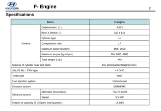
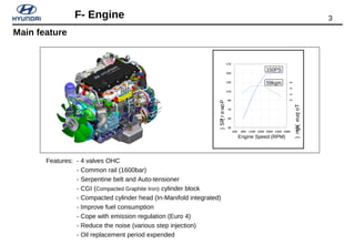
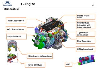
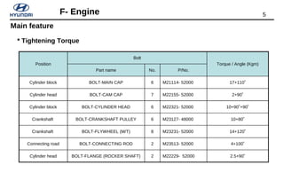
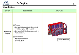
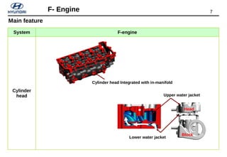
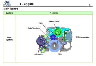
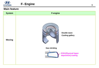
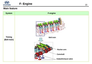
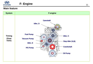
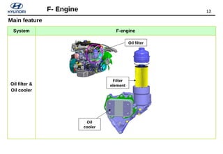
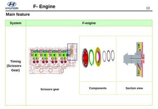
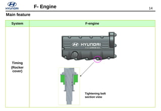
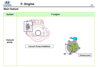
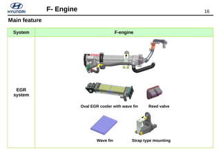
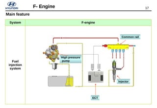
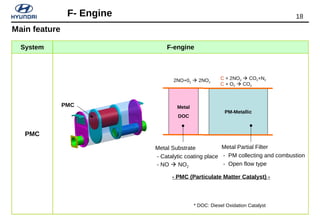
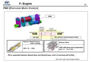
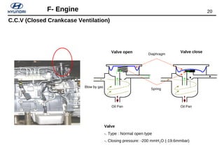
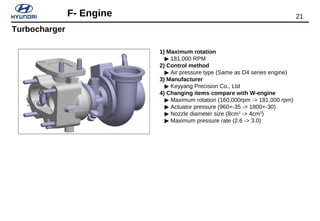
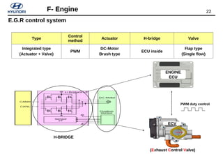
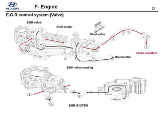
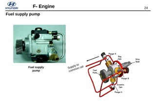
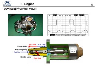
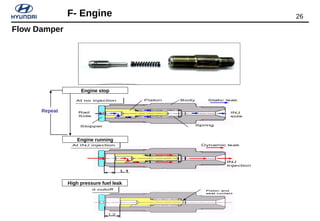
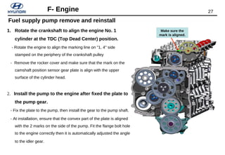
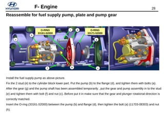
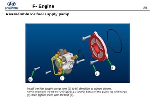
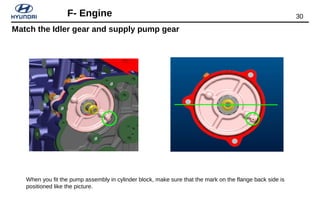
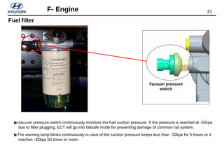
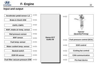
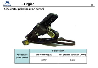
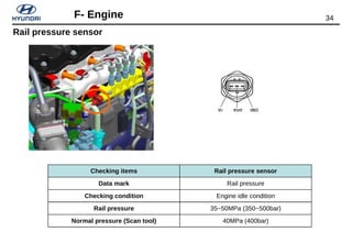
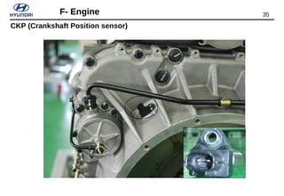
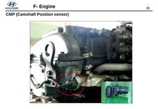
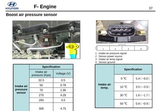
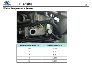
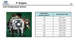
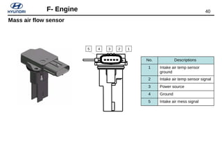
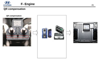
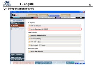
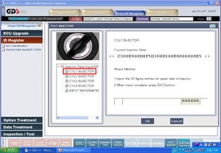
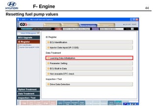
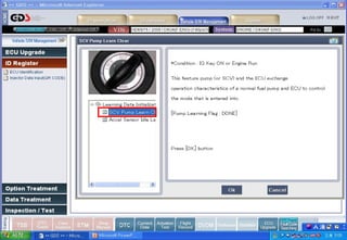
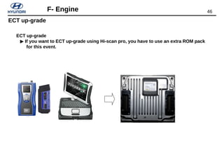
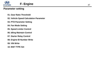
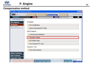
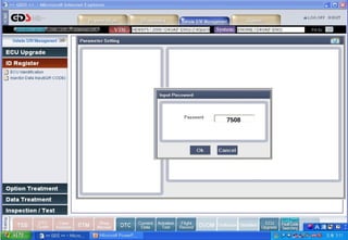
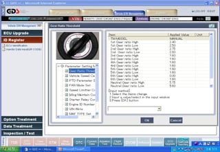
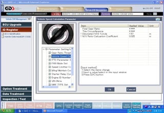
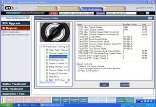
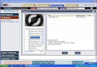
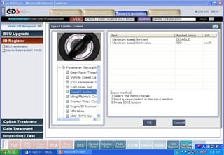
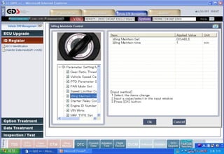

This document provides technical specifications and descriptions for the F-engine from Hyundai Motor Company. It includes details on displacement, bore/stroke, cylinder type, compression ratio, power/torque output, weight, materials, valves, fuel injection system, and more. Diagrams and descriptions are provided for various engine systems like the timing systems, oil filter/cooler, EGR system, fuel injection, PMC, sensors, and more. Removal and installation procedures are outlined for components like the fuel supply pump. Parameter settings for the ECT are also discussed.


