The document describes an e-ticketing project for online railway reservation. It includes sections on abstract, introduction, modules with examples and UML diagrams, and interfaces. The project aims to develop software for online railway ticket booking, reservation, cancellation and checking availability. It provides key features like booking tickets from home, payment options, and transaction security. UML diagrams like use case diagram, class diagram, sequence diagram and activity diagrams are used to model different aspects of the system.
SOFTWARE ENGINEERING
PROJECT BASEDLAB REPORT
On
E-TICKETING
BY: E. NANDANA PRIYANKA
CONTENTS
1. ABSTRACT
2. INTRODUCTION
3. ABOUT PROJECT
4. MODULES:EXAMPLES
5. MODULES WITH UML DIAGRAMS
6. INTERFACE DIAGRAMS
7. CONCLUSION
2.
ABSTRACT
An Electronic ticket(commonly abbreviated as e-ticket) is a digital ticket. The term is most
commonly associated with railway issued tickets. Electronic ticketing for urban or rail public
transport is usually referred to as travel card or transit pass. It is also used in ticketing in the
entertainment industry.
An electronic ticket system is a more efficient method of ticket entry, processing and marketing
for companies in the railways, flight and other transport and entertainment industries.
E-Ticketing is basically made for providing the customer an anytime and anywhere
service for booking tickets
It provides all the information and makes the customer to select their option sitting in
respective houses without moving.
E-Ticketing also provides the choices in selecting the method to pay like
Net Banking
Credit Cards
Debit Cards
E-Ticketing ensures the safe method of paying. It gives high security to your card
number, pin numbers and transactions.
The principal advantage of e-ticketing is the fact that it reduces booking expense by eliminating
the need for printing and mailing paper documents. Another advantage is that it eliminates the
possibility of critical documents getting lost in the mail or being sent to the wrong address.
3.
INTRODUCTION:
(I) PROJECT:
Our projectis carried out to develop software for online Railway Reservation System. This
system has various options like reservation, cancellation and to view details about available
seats. Our project mainly simulates the role of a Railway ticket booking officer, in a
computerized way.
The reservation option enables a person to reserve for a ticket at their home itself. All he/ she
has to do is to just login and enter the required details. After this the reservation database is
updated with the person details, train name and also the source and destination place.
The cancellation option enables the passenger to cancel the tickets that has been already
booked by him/her.
The availability option prompts the person to enter train number, train name and date of travel.
After this the availability database is accessed and available positions are produced.
(II) SOFTWARE REQUIREMENT SPECIFICATION
INTRODUCTION:
The manual system of ticket reservation takes more time and the number of reservations per
day is limited. To increase the efficiency of the process, we go for online ticket reservation
system. This system supports online ticket booking.
PURPOSE
If the entire process of reservation is done in a manual manner, then it would take
several months for reservation to reach the applicant. Considering the fact that the number of
passenger is increasing every year, an Automated System becomes essential to meet the
demand. So this system uses several programming and database techniques to elucidate the
work involved in this process. As this is a matter of National Security, the system has been
carefully verified and validated in order to satisfy it.
SCOPE:
• The System provides an online interface to the user where they can fill in their
personal details and submit the necessary documents (may be by scanning).
• The authority concerned with the issue of railway can use this system to reduce
his workload and process the application in a speedy manner.
• Passenger will come to know their status of application and the date in which
they must subject themselves for manual document verification.
4.
OVERVIEW
SRS includes twosections overall description and specific requirements –
Overall Description will describe major role of the system components and
interconnections.
Specific Requirements will describe roles & functions of the actors.
OVERALL DESCRIPTION
PRODUCT PERSPECTIVE
This system tries to make the interface as simple as possible and at the same time not
risking the security of data stored in. This minimizes the time duration in which the user
receives the ticket.
SOFTWARE INTERFACE
• Front End Client - The passenger and System online interface is built using JSP and HTML.
The Administrators’ local interface is built using Java.
• Web Server – Apache Tomcat Server (Oracle Corporation)
• Back End - Oracle 11g database
HARDWARE INTERFACE
The server is directly connected to the client systems. The client systems have access
to the database in the server.
SYSTEM FUNCTIONS
• Secure Registration of information by the Passengers.
• System can generate reports from the information and is the only authorized
personnel to add the eligible application information to the database.
• Display the requested pages to the user.
5.
USER CHARACTERISTICS
• Passenger- They are the people who desire to obtain the ticket and submit the
information to the database.
CONSTRAINTS
• The passengers require a computer to submit their information.
• Although the security is given high importance, there is always a chance of intrusion
in the web world which requires constant monitoring.
• The user has to be careful while submitting the information. Much care is required.
ASSUMPTIONS AND DEPENDENCIES
• The Passengers must have basic knowledge of computers and English Language.
• The passengers may be required to scan the documents and send.
6.
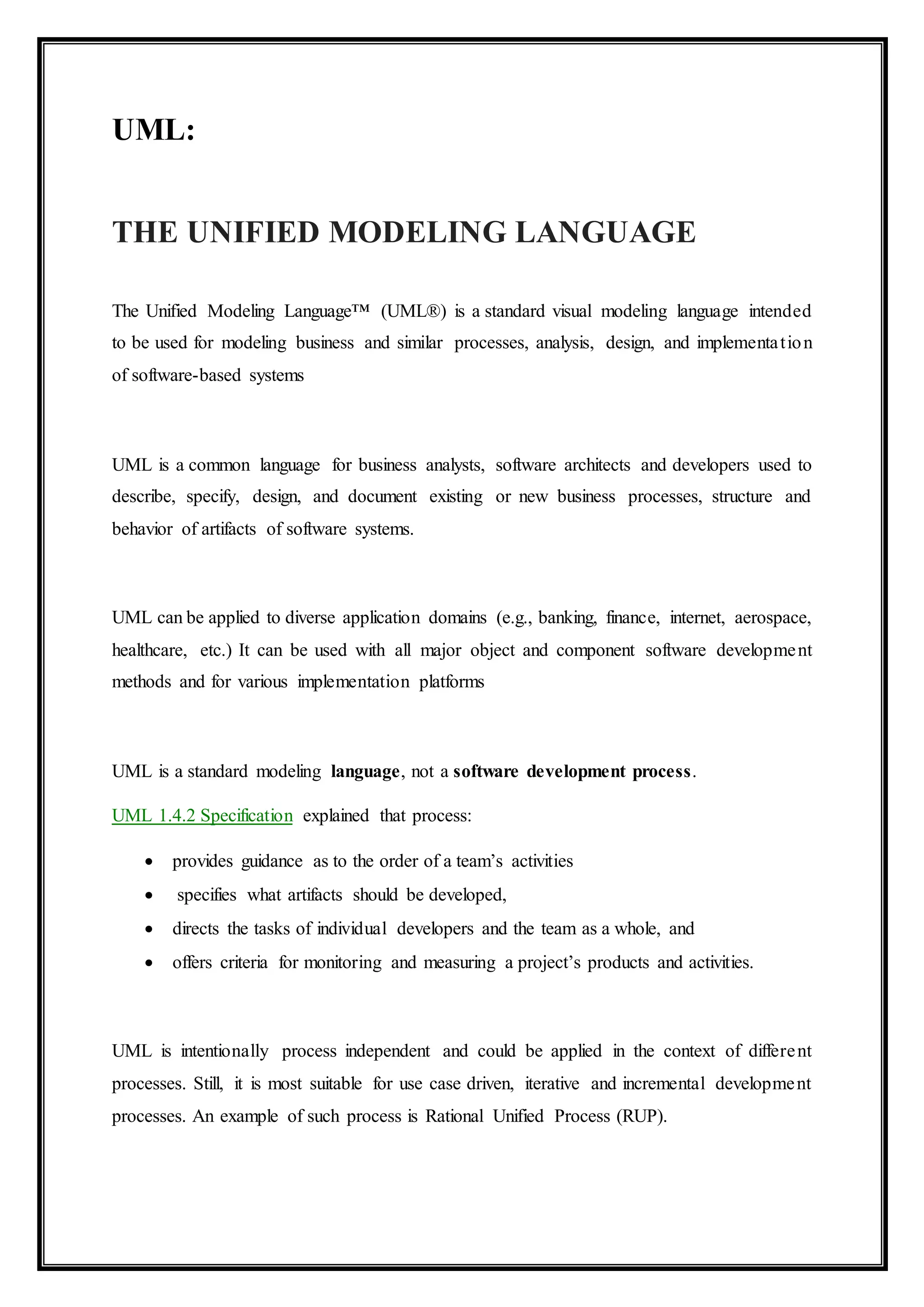
UML:
THE UNIFIED MODELINGLANGUAGE
The Unified Modeling Language™ (UML®) is a standard visual modeling language intended
to be used for modeling business and similar processes, analysis, design, and implementation
of software-based systems
UML is a common language for business analysts, software architects and developers used to
describe, specify, design, and document existing or new business processes, structure and
behavior of artifacts of software systems.
UML can be applied to diverse application domains (e.g., banking, finance, internet, aerospace,
healthcare, etc.) It can be used with all major object and component software development
methods and for various implementation platforms
UML is a standard modeling language, not a software development process.
UML 1.4.2 Specification explained that process:
provides guidance as to the order of a team’s activities
specifies what artifacts should be developed,
directs the tasks of individual developers and the team as a whole, and
offers criteria for monitoring and measuring a project’s products and activities.
UML is intentionally process independent and could be applied in the context of different
processes. Still, it is most suitable for use case driven, iterative and incremental development
processes. An example of such process is Rational Unified Process (RUP).
7.
DIAGRAMS:
USE-CASE DIAGRAM
The onlineticket reservation system uses the following use cases:
1. Request for seat availability
2. Make Reservation
3. Cancellation
4. Check status
5. Print ticket
ACTORS INVOLVED:
1) System
2) Passenger
USE-CASE NAME: REQUEST FOR SEAT AVAILABILITY
The passenger can view the train available in the database for deciding which train ticket he
wishes to reserve. The passenger can search the train information based on journey date, train
type and reservation type. The passenger can view the details of flights such as, train number,
source station, destination station, arrival time, departure time, fare and number of seats
available.
USE-CASE NAME: MAKE RESERVATION
The user is allowed to reserve a ticket on train as he/she requires on the particular date and
time. The user has to provide details such as name, train number, date of travel, source station,
destination station, proof name and money transaction details.
USE-CASE NAME: PRINT TICKET
The user after booking a ticket can print a copy of the ticket reserved. The user has to
provide the details about ticket number for searching in the database and passenger name for
confirming passenger identity.
USE-CASE NAME: CANCEL TICKET
A passenger can decide to cancel a ticket after the ticket is booked. The passenger has
to provide details about ticket for searching and details about him for confirmation of identity.
USE-CASE NAME: CHECK STATUS
The passenger can view the status of the reserved tickets. So the passenger can confirm his/her
travel.
8.
USE-CASE DIAGRAM FORRAILWAYRESERVATION
request for seat availability
cancellation
check status
Passenger
System
print report
Make Reservation
<<include>>
9.
CLASS DIAGRAM:
The classdiagram, also referred to as object modeling is the main static analysis diagram. The
main task of object modeling is to graphically show what each object will do in the problem
domain. The problem domain describes the structure and the relationships among objects.
.
The online ticket reservation system makes use of the following classes:
1. Ticket Reservation
2. Train Info
3. Passenger Info
4. Seat Avail Status
1. TICKETRESERVATION
It consists of twelve attributes and two operations. It records the details of every ticket
booked such as ticket number, passenger ID, source and destination station and etc.
2. TRAIN INFO
It stores the details of all the trains such as train number, train name, speed, source and
destination stations, etc.
3. PASSENGER INFO
It consists of seven attributes and three operations. This class is used to store passenger
details such as, passenger name, age, address and etc.
4. SEAT AVAIL STATUS
This class is used to update the number of seats available for a particular train by using update
Status () operation.
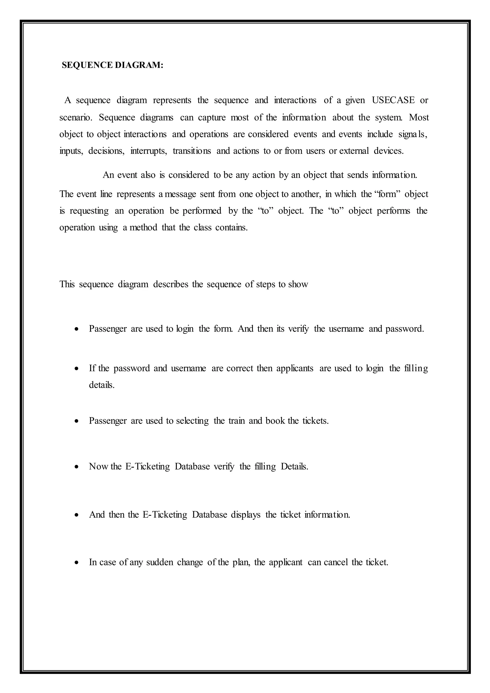
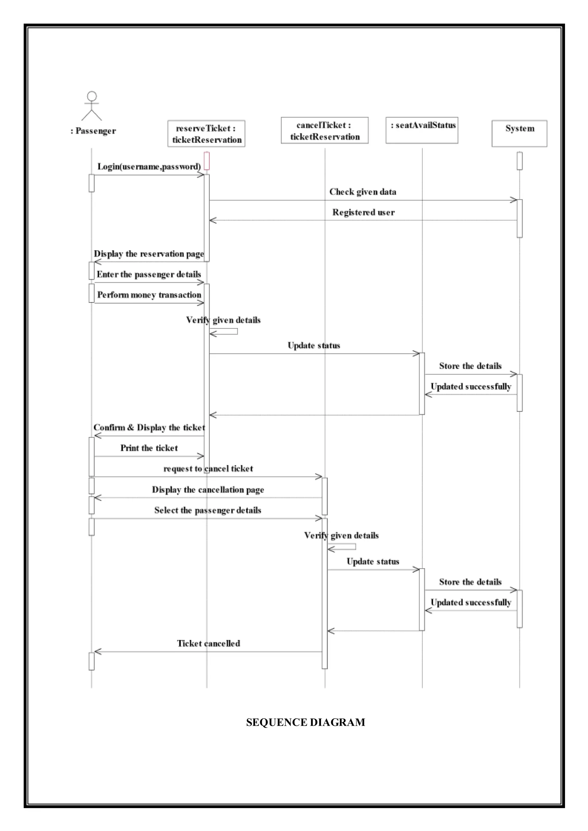
SEQUENCE DIAGRAM:
A sequencediagram represents the sequence and interactions of a given USECASE or
scenario. Sequence diagrams can capture most of the information about the system. Most
object to object interactions and operations are considered events and events include signals,
inputs, decisions, interrupts, transitions and actions to or from users or external devices.
An event also is considered to be any action by an object that sends information.
The event line represents a message sent from one object to another, in which the “form” object
is requesting an operation be performed by the “to” object. The “to” object performs the
operation using a method that the class contains.
This sequence diagram describes the sequence of steps to show
Passenger are used to login the form. And then its verify the username and password.
If the password and username are correct then applicants are used to login the filling
details.
Passenger are used to selecting the train and book the tickets.
Now the E-Ticketing Database verify the filling Details.
And then the E-Ticketing Database displays the ticket information.
In case of any sudden change of the plan, the applicant can cancel the ticket.
ACTIVITY DIAGRAM:
Activity diagramsare graphical representations of workflows of stepwise activities and actions
with support for choice, iteration and concurrency. In the Unified Modeling Language, activity
diagrams can be used to describe the business and operational step-by step workflows of
components in a system. An activity diagram shows the overall flow of control. An activity is
shown as a rounded box containing the name of the operation.
This activity diagram describes the behavior of the system.
• First state is login where the passenger login to the E-Ticketing system.
• The next state is filling details the passenger is used to fill the form.
• Then passenger used to select the flight.
• The passenger appears for book ticket and search details from E-Ticketing Database.
ACTIVITY DIAGRAM [Check Availability]
Check seat availability based on
date/ train/reservation type
Is it valid
data?
Show the
error page
No
Display the required
train information
Yes
INTERFACES:
IMPLEMENTATIONOF USER INTERFACELAYER:
CONCLUSION:
Thus the mini project for E-TICKETING with example of railway reservation system
has been successfully done along with some sample interfaces of users.


![ACTIVITY DIAGRAM:
Activity diagrams are graphical representations of workflows of stepwise activities and actions
with support for choice, iteration and concurrency. In the Unified Modeling Language, activity
diagrams can be used to describe the business and operational step-by step workflows of
components in a system. An activity diagram shows the overall flow of control. An activity is
shown as a rounded box containing the name of the operation.
This activity diagram describes the behavior of the system.
• First state is login where the passenger login to the E-Ticketing system.
• The next state is filling details the passenger is used to fill the form.
• Then passenger used to select the flight.
• The passenger appears for book ticket and search details from E-Ticketing Database.
ACTIVITY DIAGRAM [Check Availability]
Check seat availability based on
date/ train/reservation type
Is it valid
data?
Show the
error page
No
Display the required
train information
Yes](https://image.slidesharecdn.com/e-ticketing-161111065155/75/E-TICKETING-ON-RAILWAY-TICKET-RESERVATION-13-2048.jpg)
![ACTIVITY DIAGRAM [Ticket Reservation]](https://image.slidesharecdn.com/e-ticketing-161111065155/75/E-TICKETING-ON-RAILWAY-TICKET-RESERVATION-14-2048.jpg)
![ACTIVITY DIAGRAM [Check Status]
request to check
pnr status
Enter the PNR
number
Display
the status
Is valid PNR
no?
Invalid PNR
number
No
Yes](https://image.slidesharecdn.com/e-ticketing-161111065155/75/E-TICKETING-ON-RAILWAY-TICKET-RESERVATION-15-2048.jpg)
![ACTIVITYDIAGRAM [Ticket Cancellation]](https://image.slidesharecdn.com/e-ticketing-161111065155/75/E-TICKETING-ON-RAILWAY-TICKET-RESERVATION-16-2048.jpg)

![SEQUENCE DIAGRAM:
ACTIVITY DIAGRAM:
ACTIVITY DIAGRAM [Check Availability]](https://image.slidesharecdn.com/e-ticketing-161111065155/75/E-TICKETING-ON-RAILWAY-TICKET-RESERVATION-18-2048.jpg)
![ACTIVITY DIAGRAM [Check Status]
ACTIVITY DIAGRAM [Ticket Cancellation]](https://image.slidesharecdn.com/e-ticketing-161111065155/75/E-TICKETING-ON-RAILWAY-TICKET-RESERVATION-19-2048.jpg)