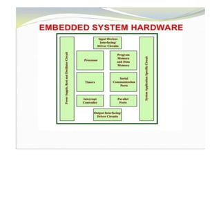
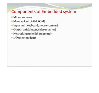
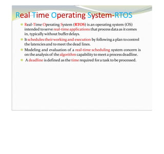
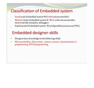
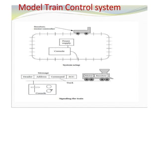
1. The document discusses embedded system design and embedded computing. It covers topics like components of embedded systems, real-time operating systems, challenges in embedded system design, and performance analysis.
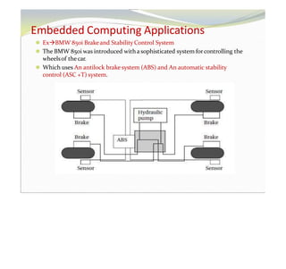
2. It provides examples of embedded applications like ABS and stability control systems in cars that use microprocessors. Complex algorithms, user interfaces, real-time deadlines, and multirate behavior are characteristics of embedded computing applications.
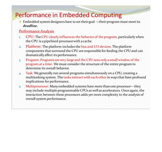
3. Choosing hardware, meeting deadlines, minimizing power consumption, and designing for upgradability are some of the challenges in embedded system design discussed in the document. The CPU, platform, program, tasks, and multiprocessor impact performance in embedded computing systems.