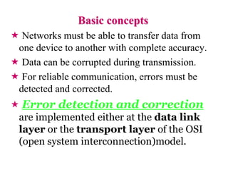
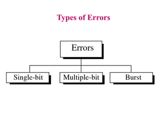
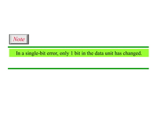
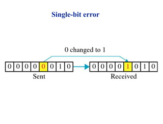
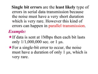
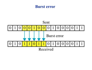
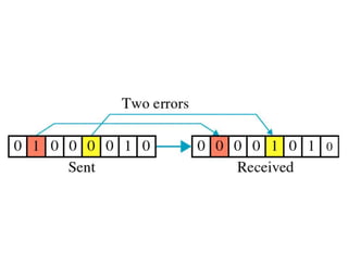
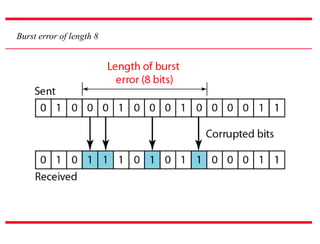
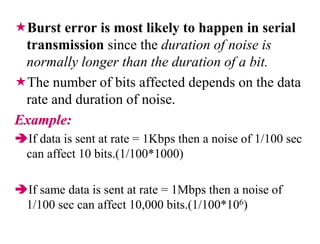
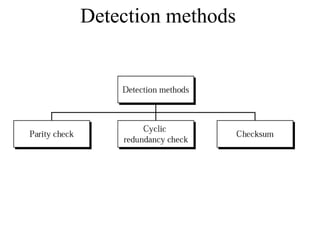
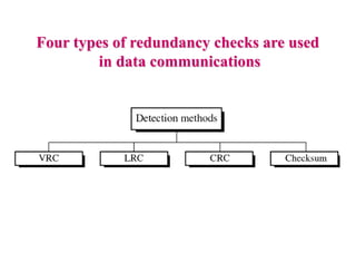
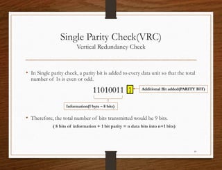
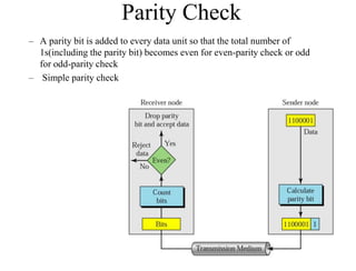
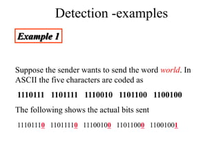
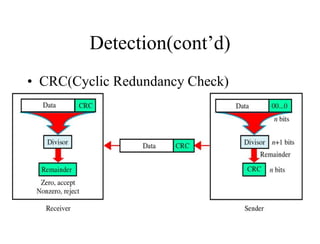
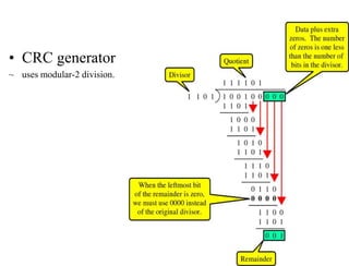
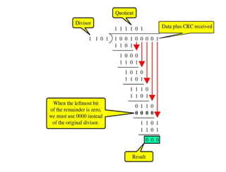
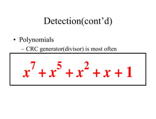
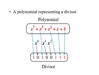
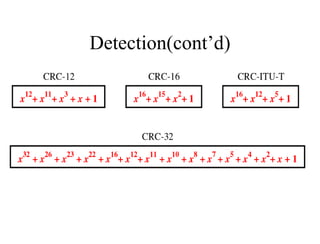
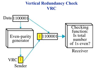
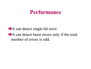
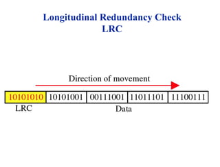
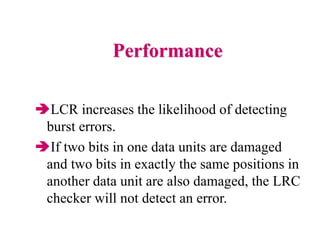
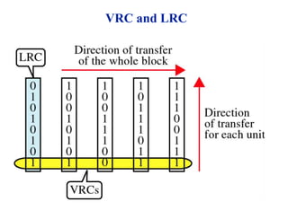
Error Detection
and Correction
• Types of Errors
• Detection
• Correction
Basic concepts
 Networks must be able to transfer data from
one device to another with complete accuracy.
 Data can be corrupted during transmission.
 For reliable communication, errors must be
detected and corrected.
 Error detection and correction
are implemented either at the data link
layer or the transport layer of the OSI
(open system interconnection)model.
Types of Errors
In a single-bit error, only 1 bit in the data unit has changed.
Note
Single-bit error
Single bit errors are the least likely type of
errors in serial data transmission because
the noise must have a very short duration
which is very rare. However this kind of
errors can happen in parallel transmission.
Example:
If data is sent at 1Mbps then each bit lasts
only 1/1,000,000 sec. or 1 μs.
For a single-bit error to occur, the noise
must have a duration of only 1 μs, which is
very rare.
Burst error
A burst error means that 2 or more bits in the data unit have
changed.
Note
The term burst error means that two or more bits in
the data unit have changed from 1 to 0 or from 0 to
1.
Burst errors does not necessarily mean that the
errors occur in consecutive bits, the length of the
burst is measured from the first corrupted bit to the
last corrupted bit. Some bits in between may not
have been corrupted.
Burst error of length 8
Burst error is most likely to happen in serial
transmission since the duration of noise is
normally longer than the duration of a bit.
The number of bits affected depends on the data
rate and duration of noise.
Example:
If data is sent at rate = 1Kbps then a noise of 1/100 sec
can affect 10 bits.(1/100*1000)
If same data is sent at rate = 1Mbps then a noise of
1/100 sec can affect 10,000 bits.(1/100*106)
Error detection
Error detection means to decide whether the
received data is correct or not without having a
copy of the original message.
Error detection uses the concept of redundancy,
which means adding extra bits for detecting
errors at the destination.
Redundancy
Redundancy (cont’d)
Detection methods
Four types of redundancy checks are used
in data communications
Single Parity Check(VRC)
Vertical Redundancy Check
• In Single parity check, a parity bit is added to every data unit so that the total
number of 1s is even or odd.
11010011 1
• Therefore, the total number of bits transmitted would be 9 bits.
( 8 bits of information + 1 bit parity = n data bits into n+1 bits)
18
Information(1 byte – 8 bits)
Additional Bit added(PARITY BIT)
Parity Check
– A parity bit is added to every data unit so that the total number of
1s(including the parity bit) becomes even for even-parity check or odd
for odd-parity check
– Simple parity check
How is the even parity bit generated?
Total number of ‘1’s should be even.
If the byte that we want to transmit is:
• Step 1: count the number of 1’s in the byte.
• Answer: 5
• Step 2: compute the parity value.
• Since the total number of 1’s is 5, the even parity bit will have a value of 1.
• If the number of bits are already even, the parity bit will be ‘0’.
20
1 0 1 0 1 1 0 1
1 0 1 0 1 1 0 1 1
How is the odd parity bit generated?
Total number of ‘1’s should be odd.
If the byte that we want to transmit is:
• Step 1: count the number of 1’s in the byte.
• Answer: 4
• Step 2: compute the parity value.
• Since the total number of 1’s is 4, the odd parity bit will have a value of 1.
• If the number of bits are already odd, the parity bit will be ‘0’.
21
1 0 1 0 1 1 0 0
1 0 1 0 1 1 0 0 1
Detection -examples
Example 1
Suppose the sender wants to send the word world. In
ASCII the five characters are coded as
1110111 1101111 1110010 1101100 1100100
The following shows the actual bits sent
11101110 11011110 11100100 11011000 11001001
Detection – examples
Example 2
Now suppose the word world in Example 1 is received
by the receiver without being corrupted in transmission.
11101110 11011110 11100100 11011000
11001001
The receiver counts the 1s in each character and comes
up with even numbers (6, 6, 4, 4, 4). The data are
accepted.
Detection – examples
Example 3
Now suppose the word world in Example 1 is
corrupted during transmission.
11111110 11011110 11101100 11011000
11001001
The receiver counts the 1s in each character and comes
up with even and odd numbers (7, 6, 5, 4, 4). The
receiver knows that the data are corrupted, discards
them, and asks for retransmission.
Two Dimensional Parity Check(LRC)
Longitudinal Redundancy Check
Detection - example
Example 4
Suppose the following block is sent:
10101001 00111001 11011101 11100111 10101010
However, it is hit by a burst noise of length 8, and some bits are
corrupted.
10100011 10001001 11011101 11100111 10101010
When the receiver checks the parity bits, some of the bits do not
follow the even-parity rule and the whole block is discarded.
10100011 10001001 11011101 11100111 10101010
Two Dimensional Parity Generation
Even Parity Concept
27
1100111 1011101 0111001 0101001
1 1 0 0 1 1 1
1 0 1 1 1 0 1
0 1 1 1 0 0 1
0 1 0 1 0 0 1
Original Data
1100111 1011101 0111001 0101001
Row Parity
No ‘1’s : 5
No ‘1’s : 5
No ‘1’s : 4
No ‘1’s : 3
No ‘1’s : 3
1
1
1
0
1
1 0 1
0 1 0 1 0 1 0 1
1
0101010
Column Parity
This will
Send
Detection(cont’d)
• CRC(Cyclic Redundancy Check)
~ is based on binary division.
• CRC generator
~ uses modular-2 division.
Binary Division
in a
CRC Generator
Binary Division
in a
CRC Checker
Detection(cont’d)
• Polynomials
– CRC generator(divisor) is most often
represented not as a string of 1s and 0s, but as
an algebraic polynomial.
• A polynomial representing a divisor
Detection(cont’d)
• Standard polynomials
Vertical Redundancy Check
VRC
Performance
It can detect single bit error
It can detect burst errors only if the total
number of errors is odd.
Longitudinal Redundancy Check
LRC
Performance
LCR increases the likelihood of detecting
burst errors.
If two bits in one data units are damaged
and two bits in exactly the same positions in
another data unit are also damaged, the LRC
checker will not detect an error.
VRC and LRC

ERROR_DETECTION.pptx

  • 1.
    Error Detection and Correction •Types of Errors • Detection • Correction
  • 2.
    Basic concepts  Networksmust be able to transfer data from one device to another with complete accuracy.  Data can be corrupted during transmission.  For reliable communication, errors must be detected and corrected.  Error detection and correction are implemented either at the data link layer or the transport layer of the OSI (open system interconnection)model.
  • 3.
  • 4.
    In a single-biterror, only 1 bit in the data unit has changed. Note
  • 5.
  • 6.
    Single bit errorsare the least likely type of errors in serial data transmission because the noise must have a very short duration which is very rare. However this kind of errors can happen in parallel transmission. Example: If data is sent at 1Mbps then each bit lasts only 1/1,000,000 sec. or 1 μs. For a single-bit error to occur, the noise must have a duration of only 1 μs, which is very rare.
  • 7.
  • 8.
    A burst errormeans that 2 or more bits in the data unit have changed. Note
  • 10.
    The term bursterror means that two or more bits in the data unit have changed from 1 to 0 or from 0 to 1. Burst errors does not necessarily mean that the errors occur in consecutive bits, the length of the burst is measured from the first corrupted bit to the last corrupted bit. Some bits in between may not have been corrupted.
  • 11.
  • 12.
    Burst error ismost likely to happen in serial transmission since the duration of noise is normally longer than the duration of a bit. The number of bits affected depends on the data rate and duration of noise. Example: If data is sent at rate = 1Kbps then a noise of 1/100 sec can affect 10 bits.(1/100*1000) If same data is sent at rate = 1Mbps then a noise of 1/100 sec can affect 10,000 bits.(1/100*106)
  • 13.
    Error detection Error detectionmeans to decide whether the received data is correct or not without having a copy of the original message. Error detection uses the concept of redundancy, which means adding extra bits for detecting errors at the destination.
  • 14.
  • 15.
  • 16.
  • 17.
    Four types ofredundancy checks are used in data communications
  • 18.
    Single Parity Check(VRC) VerticalRedundancy Check • In Single parity check, a parity bit is added to every data unit so that the total number of 1s is even or odd. 11010011 1 • Therefore, the total number of bits transmitted would be 9 bits. ( 8 bits of information + 1 bit parity = n data bits into n+1 bits) 18 Information(1 byte – 8 bits) Additional Bit added(PARITY BIT)
  • 19.
    Parity Check – Aparity bit is added to every data unit so that the total number of 1s(including the parity bit) becomes even for even-parity check or odd for odd-parity check – Simple parity check
  • 20.
    How is theeven parity bit generated? Total number of ‘1’s should be even. If the byte that we want to transmit is: • Step 1: count the number of 1’s in the byte. • Answer: 5 • Step 2: compute the parity value. • Since the total number of 1’s is 5, the even parity bit will have a value of 1. • If the number of bits are already even, the parity bit will be ‘0’. 20 1 0 1 0 1 1 0 1 1 0 1 0 1 1 0 1 1
  • 21.
    How is theodd parity bit generated? Total number of ‘1’s should be odd. If the byte that we want to transmit is: • Step 1: count the number of 1’s in the byte. • Answer: 4 • Step 2: compute the parity value. • Since the total number of 1’s is 4, the odd parity bit will have a value of 1. • If the number of bits are already odd, the parity bit will be ‘0’. 21 1 0 1 0 1 1 0 0 1 0 1 0 1 1 0 0 1
  • 22.
    Detection -examples Example 1 Supposethe sender wants to send the word world. In ASCII the five characters are coded as 1110111 1101111 1110010 1101100 1100100 The following shows the actual bits sent 11101110 11011110 11100100 11011000 11001001
  • 23.
    Detection – examples Example2 Now suppose the word world in Example 1 is received by the receiver without being corrupted in transmission. 11101110 11011110 11100100 11011000 11001001 The receiver counts the 1s in each character and comes up with even numbers (6, 6, 4, 4, 4). The data are accepted.
  • 24.
    Detection – examples Example3 Now suppose the word world in Example 1 is corrupted during transmission. 11111110 11011110 11101100 11011000 11001001 The receiver counts the 1s in each character and comes up with even and odd numbers (7, 6, 5, 4, 4). The receiver knows that the data are corrupted, discards them, and asks for retransmission.
  • 25.
    Two Dimensional ParityCheck(LRC) Longitudinal Redundancy Check
  • 26.
    Detection - example Example4 Suppose the following block is sent: 10101001 00111001 11011101 11100111 10101010 However, it is hit by a burst noise of length 8, and some bits are corrupted. 10100011 10001001 11011101 11100111 10101010 When the receiver checks the parity bits, some of the bits do not follow the even-parity rule and the whole block is discarded. 10100011 10001001 11011101 11100111 10101010
  • 27.
    Two Dimensional ParityGeneration Even Parity Concept 27 1100111 1011101 0111001 0101001 1 1 0 0 1 1 1 1 0 1 1 1 0 1 0 1 1 1 0 0 1 0 1 0 1 0 0 1 Original Data 1100111 1011101 0111001 0101001 Row Parity No ‘1’s : 5 No ‘1’s : 5 No ‘1’s : 4 No ‘1’s : 3 No ‘1’s : 3 1 1 1 0 1 1 0 1 0 1 0 1 0 1 0 1 1 0101010 Column Parity This will Send
  • 28.
    Detection(cont’d) • CRC(Cyclic RedundancyCheck) ~ is based on binary division.
  • 29.
    • CRC generator ~uses modular-2 division. Binary Division in a CRC Generator
  • 30.
  • 31.
    Detection(cont’d) • Polynomials – CRCgenerator(divisor) is most often represented not as a string of 1s and 0s, but as an algebraic polynomial.
  • 32.
    • A polynomialrepresenting a divisor
  • 33.
  • 34.
  • 35.
    Performance It can detectsingle bit error It can detect burst errors only if the total number of errors is odd.
  • 36.
  • 37.
    Performance LCR increases thelikelihood of detecting burst errors. If two bits in one data units are damaged and two bits in exactly the same positions in another data unit are also damaged, the LRC checker will not detect an error.
  • 38.