Basic concepts
Basic concepts
Networks must be able to transfer data from
one device to another with complete accuracy.
Data can be corrupted during transmission.
For reliable communication, errors must be
detected and corrected.
Error detection and correction
are implemented either at the data link
layer or the transport layer of the OSI
model.
Single bit errorsare the least likely type of errors in serial data
transmission because the noise must have a very short duration
which is very rare. However this kind of errors can happen in
parallel transmission.
Example:
Example:
• If data is sent at a rate of 1 Mbps (1 million bits per second),
each bit will have a duration of 1 microsecond (1 μs).
• For a single-bit error to occur, noise would need to affect the
transmission for exactly 1 μs, which is quite rare in typical noise
conditions because noise often lasts longer or affects multiple bits
simultaneously.
However, in parallel transmission, where multiple bits are sent
simultaneously over multiple channels, single-bit errors can occur
more frequently. Each bit in a parallel stream could potentially be
affected by independent noise on one of the channels, leading to a
higher chance of single-bit errors in the transmission.
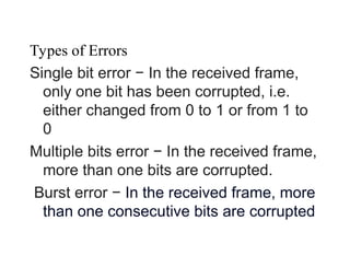
Types of Errors
Singlebit error − In the received frame,
only one bit has been corrupted, i.e.
either changed from 0 to 1 or from 1 to
0
Multiple bits error − In the received frame,
more than one bits are corrupted.
Burst error − In the received frame, more
than one consecutive bits are corrupted
9.
Burst error ismost likely to happen in serial
transmission since the duration of noise is
normally longer than the duration of a bit.
The number of bits affected depends on the data
rate and duration of noise.
Example:
Example:
If data is sent at rate = 1Kbps then a noise of 1/100 sec
can affect 10 bits.(1/100*1000)
If same data is sent at rate = 1Mbps then a noise of
1/100 sec can affect 10,000 bits.(1/100*106
)
10.
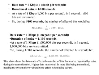
• Data rate= 1 Kbps (1 kilobit per second):
• Duration of noise = 1/100 seconds.
• At a rate of 1 Kbps (1,000 bits per second), in 1 second, 1,000
bits are transmitted.
• So, during 1/100 seconds, the number of affected bits would be:
Data rate = 1 Mbps (1 megabit per second):
•Duration of noise = 1/100 seconds.
•At a rate of 1 Mbps (1,000,000 bits per second), in 1 second,
1,000,000 bits are transmitted.
•So, during 1/100 seconds, the number of affected bits would be:
This shows how the data rate affects the number of bits that can be impacted by noise
during the same duration. Higher data rates result in more bits being transmitted,
making the system more vulnerable to errors when noise occurs.
11.
Error detection
Error detection
Errordetection means to decide whether the
received data is correct or not without having a
copy of the original message.
Error detection uses the concept of redundancy,
which means adding extra bits for detecting
errors at the destination.
12.
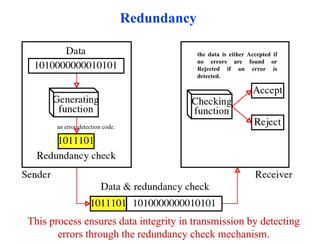
Redundancy
an error-detection code.
thedata is either Accepted if
no errors are found or
Rejected if an error is
detected.
This process ensures data integrity in transmission by detecting
errors through the redundancy check mechanism.
13.
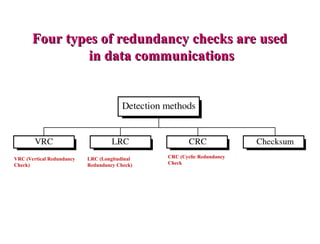
Four types ofredundancy checks are used
Four types of redundancy checks are used
in data communications
in data communications
VRC (Vertical Redundancy
Check)
LRC (Longitudinal
Redundancy Check)
CRC (Cyclic Redundancy
Check
14.
Vertical Redundancy Check
VRC
•Alsoknown as Parity Check.
•It adds a parity bit to the data to ensure that the total number of 1's in the
transmitted word (including the parity bit) is either even or odd.
•Used to detect single-bit errors.
•Sender Side:
•The data to be sent is shown as a binary sequence (e.g., 1100001).
•An even-parity generator examines the data and calculates whether the total number of
1's is even or odd.
•In this case, the data contains an odd number of 1's (three), so the parity generator adds a
1 (highlighted in yellow) to make the total count of 1's even.
•The new data sequence 11100001(including the parity bit) is then transmitted to the
receiver.
•Receiver Side:
•The checking function at the receiver verifies whether the total number of 1's in the
received sequence is even.
•If the number of 1's is even, the data is assumed to be correct and is accepted.
•If the number of 1's is odd, it indicates a possible transmission error, and the data may be
rejected.
Let’s assume weare transmitting the following 4-bit data units:
•Data 1: 1100
•Data 2: 1010
•Data 3: 0110
•Data 4: 1001
Step 1: Calculate the parity bit for each data unit (using even parity)
For each data unit, we calculate a parity bit such that the total number of 1's (including the parity bit) is even.
•Data 1: 1100
•Number of 1's: 2 (already even)
•Parity bit: 0
•Transmitted Data: 01100
•Data 2: 1010
•Number of 1's: 2 (already even)
•Parity bit: 0
•Transmitted Data: 01010
•Data 3: 0110
•Number of 1's: 2 (already even)
•Parity bit: 0
•Transmitted Data: 00110
•Data 4: 1001
•Number of 1's: 2 (already even)
•Parity bit: 0
•Transmitted Data: 01001
Vertical Redundancy Check
VRC
17.
Step 2: Transmission
Thesender transmits the data with the parity bits appended. So, the transmitted data is:
•01100, 01010, 00110, 01001
Step 3: Receiver Side Check
At the receiver side, the receiver performs the same parity check by counting the number of 1's
in each received unit (including the parity bit).
•For 01100: Number of 1's = 2 (even) → Data is correct.
•For 01010: Number of 1's = 2 (even) → Data is correct.
•For00110: Number of 1's = 2 (even) → Data is correct.
•For 01001: Number of 1's = 2 (even) → Data is correct.
If the parity check at the receiver shows an odd number of 1's in any unit, it indicates that an
error occurred during transmission.
Example of an Error:
Suppose during transmission, the second data unit 10100 becomes 11100 due to a bit flip:
•Received Data: 11100
•Number of 1's: 3 (odd) → Error detected.
The receiver would reject the data or request retransmission in this case.
Vertical Redundancy Check
VRC
Longitudinal Redundancy CheckLRC
Longitudinal Redundancy Check (LRC) is also known as 2-D parity check. In this method,
data which the user want to send is organised into tables of rows and columns. A block of
bit is divided into table or matrix of rows and columns. In order to detect an error, a
redundant bit is added to the whole block and this block is transmitted to receiver. The
receiver uses this redundant row to detect error. After checking the data for errors,
receiver accepts the data and discards the redundant row of bits.
Example :
If a block of 32 bits is to be transmitted, it is divided into matrix of four rows and eight
columns which as shown in the following figure
In this matrix of bits, a parity bit (odd or even) is calculated for each column. It
means 32 bits data plus 8 redundant bits are transmitted to receiver.
Whenever data reaches at the destination, receiver uses LRC to detect error in
data.
Advantage :
Go
Receive
r
20.
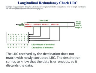
Longitudinal Redundancy CheckLRC
Example : Suppose 32 bit data plus LRC that was being transmitted is hit by a burst error of length 5 and some
bits are corrupted as shown in the following figure :
The LRC received by the destination does not
match with newly corrupted LRC. The destination
comes to know that the data is erroneous, so it
discards the data.
01001111 11001010 10101011 10111100
11100011
21.
Longitudinal Redundancy CheckLRC
Disadvantage :
The main problem with LRC is that, it is not able to detect error if two bits in a data unit
are damaged and two bits in exactly the same position in other data unit are also
damaged.
Example : If data 110011 010101 is changed to 010010110100.
The LRC received by the destination does not match with
newly corrupted LRC. The destination comes to know that
the data is erroneous, so it discards the data.
In this example 1st and 6th bit in one data unit is changed .
Also the 1st and 6th bit in second unit is changed.
22.
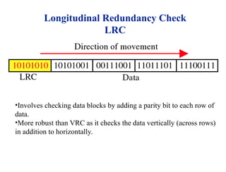
Longitudinal Redundancy Check
LRC
•Involveschecking data blocks by adding a parity bit to each row of
data.
•More robust than VRC as it checks the data vertically (across rows)
in addition to horizontally.
23.
Longitudinal Redundancy Check(LRC) is an error detection method where a parity bit is computed for each
column of bits in a data block, rather than for each row (as in Vertical Redundancy Check, VRC). It is typically
used to detect errors in data transmissions across multiple data words.
Example of LRC:Suppose we want to transmit 4 data bytes (each 7 bits long):
Step 1: Organize data into a table:
Step 2: Calculate parity for each column:We compute the parity bit for each bit position
across all 4 bytes. Here, we'll use even parity, meaning that the parity bit will make the total
number of 1's in the column even
Longitudinal Redundancy Check
LRC
24.
Bit Position Parity(Even) Calculation Parity Bit (LRC)
Bit 1 1 + 1 + 0 + 1 = 3 (odd) 1
Bit 2 0 + 1 + 1 + 0 = 2 (even) 0
Bit 3 1 + 0 + 1 + 1 = 3 (odd) 1
Bit 4 1 + 0 + 0 + 0 = 1 (odd) 1
Bit 5 0 + 1 + 1 + 1 = 3 (odd) 1
Bit 6 0 + 0 + 1 + 1 = 2 (even) 0
Bit 7 1 + 1 + 0 + 1 = 3 (odd) 1
So, the LRC parity byte is: 1011101.
Step 3: Transmit the data with LRC:
•Data bytes:
•Byte 1: 1011001
•Byte 2: 1100101
•Byte 3: 0110110
•Byte 4: 1010111
•LRC (parity byte): 1011101
Longitudinal Redundancy Check
LRC
25.
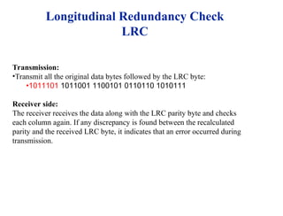
Transmission:
•Transmit all theoriginal data bytes followed by the LRC byte:
•1011101 1011001 1100101 0110110 1010111
Receiver side:
The receiver receives the data along with the LRC parity byte and checks
each column again. If any discrepancy is found between the recalculated
parity and the received LRC byte, it indicates that an error occurred during
transmission.
Longitudinal Redundancy Check
LRC
26.
Performance
Performance
LCR increases thelikelihood of detecting
burst errors.
If two bits in one data units are damaged
and two bits in exactly the same positions in
another data unit are also damaged, the
LRC checker will not detect an error.
27.
VRC and LRC
Itrepresents a block of data transmission with error detection mechanisms using LRC (Longitudinal Redundancy Check) and VRC (Vertical
Redundancy Check).
•The LRC is displayed on the left, containing the parity bits for each row of the transmitted data.
•The VRCs are displayed at the bottom, showing the parity bit for each column of the data block.
•Data transmission proceeds as shown by the arrows: the entire block (the group of bits) is transferred as a whole from left to right, and individual
units (such as bytes) are transferred in a vertical direction.
This structure is used for error detection in data transmission. The combination of LRC and VRC allows detecting single-bit errors as well as some
multiple-bit errors by checking both row and column parity.
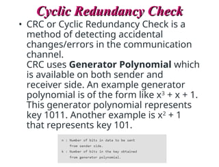
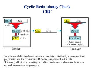
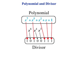
Cyclic Redundancy Check
CyclicRedundancy Check
• CRC or Cyclic Redundancy Check is a
method of detecting accidental
changes/errors in the communication
channel.
CRC uses Generator Polynomial which
is available on both sender and
receiver side. An example generator
polynomial is of the form like x3
+ x + 1.
This generator polynomial represents
key 1011. Another example is x2
+ 1
that represents key 101.
30.
Cyclic Redundancy Check
CyclicRedundancy Check
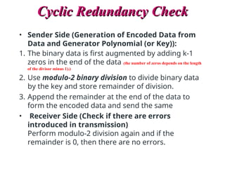
• Sender Side (Generation of Encoded Data from
Data and Generator Polynomial (or Key)):
1. The binary data is first augmented by adding k-1
zeros in the end of the data (the number of zeros depends on the length
of the divisor minus 1).)
2. Use modulo-2 binary division to divide binary data
by the key and store remainder of division.
3. Append the remainder at the end of the data to
form the encoded data and send the same
• Receiver Side (Check if there are errors
introduced in transmission)
Perform modulo-2 division again and if the
remainder is 0, then there are no errors.
31.
Cyclic Redundancy Check
CyclicRedundancy Check
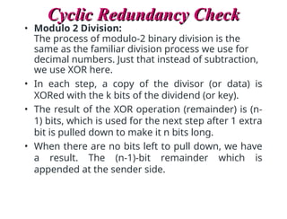
• Modulo 2 Division:
The process of modulo-2 binary division is the
same as the familiar division process we use for
decimal numbers. Just that instead of subtraction,
we use XOR here.
• In each step, a copy of the divisor (or data) is
XORed with the k bits of the dividend (or key).
• The result of the XOR operation (remainder) is (n-
1) bits, which is used for the next step after 1 extra
bit is pulled down to make it n bits long.
• When there are no bits left to pull down, we have
a result. The (n-1)-bit remainder which is
appended at the sender side.
32.
Cyclic Redundancy Check
CRC
•Apolynomial division-based method where data is divided by a predetermined
polynomial, and the remainder (CRC value) is appended to the data.
•Extremely effective in detecting errors like burst errors and commonly used in
network communication protocols.
33.
Cyclic Redundancy Check
CyclicRedundancy Check
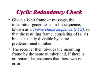
• Given a k-bit frame or message, the
transmitter generates an n-bit sequence,
known as a frame check sequence (FCS), so
that the resulting frame, consisting of (k+n)
bits, is exactly divisible by some
predetermined number.
• The receiver then divides the incoming
frame by the same number and, if there is
no remainder, assumes that there was no
error.
How CRC DivisionWorks:
1.Dividend and Divisor:
1. The dividend is the data message with extra zeros appended (equal to the length of the
divisor minus one).
2. The divisor is the generator polynomial (a fixed binary number).
2.Initial Alignment:
1. You align the divisor with the leftmost bits of the dividend (data).
2. The divisor is XORed with the first bits of the dividend.
3.Generating the Quotient:
1. At each step of the division, you perform an XOR between the divisor and the current
portion of the dividend (the bits that are aligned).
2. After the XOR, the result is used to determine whether to place a 1 or 0 in the quotient:
1. If the result starts with 1 after XORing, you place a 1 in the quotient.
2. If the result starts with 0, you place a 0 in the quotient (but this usually happens when
the next segment of the dividend has fewer bits than the divisor).
4.Shifting the Division:
1. After each XOR, you bring down the next bit of the dividend to form a new number.
2. This new number is XORed with the divisor again, and another bit is added to the quotient
based on the result.
Cyclic Redundancy Check
Cyclic Redundancy Check
Examples
Ex1:
1-Data word tobe sent - 100100
2-Key - 1101 [ Or generator polynomial x3
+ x2
+ 1]
Sender Side,
3-Receiver Side: Code word received at the
receiver side 100100001
Ex2:
1-Data word to be sent - 100100
2-Key - 1101 Sender Side:
3-Code word received at the receiver side -
100000001
40.
Example 1 (Noerror in transmission):
Data word to be sent - 100100
Key - 1101 [ Or generator polynomial x3
+ x2
+ 1] Sender Side:
Therefore, the remainder is 001 and hence the encoded data sent is 100100001.
Receiver Side: Code word received at the receiver side 100100001
Step 1
Step 2
Therefore, the remainder is all zeros. Hence, the data received has no
error.
Result
41.
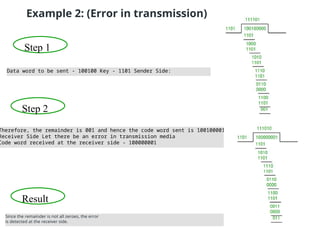
Example 2: (Errorin transmission)
Step 1
Step 2
Since the remainder is not all zeroes, the error
is detected at the receiver side.
Result
Data word to be sent - 100100 Key - 1101 Sender Side:
Therefore, the remainder is 001 and hence the code word sent is 100100001.
Receiver Side Let there be an error in transmission media
Code word received at the receiver side - 100000001
42.
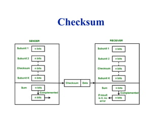
Checksum
•A simple errordetection method
where data values are summed and
the result is transmitted along with
the data.
•If the sum of the received values
matches the checksum, the data is
considered correct.
43.
At the sender
Atthe sender
The unit is divided into k sections, each of n
bits.
All sections are added together using one’s
complement to get the sum.
The sum is complemented and becomes the
checksum.
The checksum is sent with the data
44.
At the receiver
Atthe receiver
The unit is divided into k sections, each of n
bits.
All sections are added together using one’s
complement to get the sum.
The sum is complemented.
If the result is zero, the data are accepted:
otherwise, they are rejected.
Example
• Example –If the data unit to be transmitted is 10101001
00111001, the following procedure is used at Sender site and
Receiver site.
• Sender Site:
• Data transmitted to Receiver is:
• Receiver Site :
47.
Performance
Performance
The checksum detectsall errors involving an
odd number of bits.
It detects most errors involving an even number
of bits.
If one or more bits of a segment are damaged
and the corresponding bit or bits of opposite
value in a second segment are also damaged, the
sums of those columns will not change and the
receiver will not detect a problem.
48.
Example
• The mainproblem is that the error goes undetected if one
or more bits of a subunit is damaged and the
corresponding bit or bits of a subunit are damaged and
the corresponding bit or bits of opposite value in second
subunit are also damaged. This is because the sum of
those columns remains unchanged.
• Example – If the data transmitted along with checksum is
10101001 00111001 00011101. But the data received at
destination is 00101001 10111001 00011101.
• Receiver Site:
49.
Error Correction
Error Correction
Itcan be handled in two ways:
1) receiver can have the sender retransmit the
entire data unit.
2) The receiver can use an error-correcting
code, which automatically corrects certain
errors.
50.
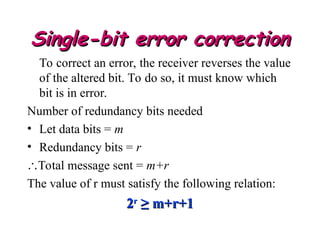
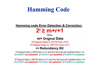
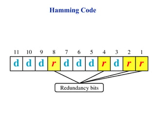
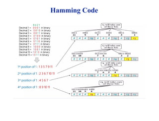
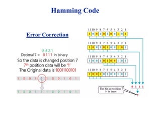
Single-bit error correction
Single-biterror correction
To correct an error, the receiver reverses the value
of the altered bit. To do so, it must know which
bit is in error.
Number of redundancy bits needed
• Let data bits = m
• Redundancy bits = r
Total message sent = m+r
The value of r must satisfy the following relation:
2
2r
r
≥ m+r+1
≥ m+r+1


![Examples
Ex1:
1-Data word to be sent - 100100
2-Key - 1101 [ Or generator polynomial x3
+ x2
+ 1]
Sender Side,
3-Receiver Side: Code word received at the
receiver side 100100001
Ex2:
1-Data word to be sent - 100100
2-Key - 1101 Sender Side:
3-Code word received at the receiver side -
100000001](https://image.slidesharecdn.com/chapter-4errordetection1-260117145203-8e1a0f07/85/Chapter-4-Error-detection-inroduction-to-detect-1-ppt-39-320.jpg)
![Example 1 (No error in transmission):
Data word to be sent - 100100
Key - 1101 [ Or generator polynomial x3
+ x2
+ 1] Sender Side:
Therefore, the remainder is 001 and hence the encoded data sent is 100100001.
Receiver Side: Code word received at the receiver side 100100001
Step 1
Step 2
Therefore, the remainder is all zeros. Hence, the data received has no
error.
Result](https://image.slidesharecdn.com/chapter-4errordetection1-260117145203-8e1a0f07/85/Chapter-4-Error-detection-inroduction-to-detect-1-ppt-40-320.jpg)


![[DSC Europe 25] Elena Menshikova - AI-Powered Operational Excellence: Revolut...](https://cdn.slidesharecdn.com/ss_thumbnails/es6nholbqy3zaao2c2yd-2-elena-menshikova-data-ai-in-decision-making-260115093812-4fba8b38-thumbnail.jpg?width=640&height=640&fit=bounds)


![[DSC Europe 25] Nikola Vasiljevic - Player segmentation by combat playstyles ...](https://cdn.slidesharecdn.com/ss_thumbnails/mnvbf0yvrwaqsipzrrv3-2-nikola-vasiljevic-player-segmentation-by-playstyles-in-action-shooter-games-260114111931-b4d766cd-thumbnail.jpg?width=640&height=640&fit=bounds)


![[DSC Europe 25] Srba Markovic - From Pilot to Production: Overcoming AI Deplo...](https://cdn.slidesharecdn.com/ss_thumbnails/yjjmrtytmwbalxlba7px-4-srba-markovic-from-pilot-to-production-overcoming-ai-deployment-blockers-with-260114111931-4a892d44-thumbnail.jpg?width=640&height=640&fit=bounds)


