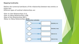
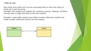
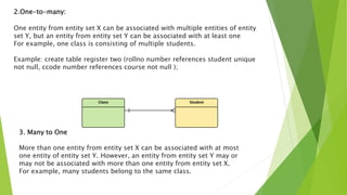
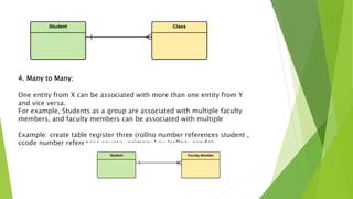
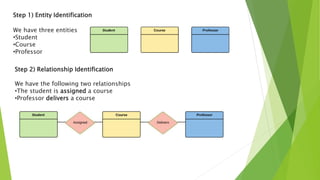
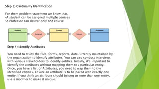
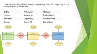
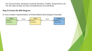
ER Diagram
BY:
Kajal Aggarwal
Mapping Cardinality
Defines the numerical attributes of the relationship between two entities or
entity sets.
Different types of cardinal relationships are:
•One-to-One Relationships (1:1)
•One-to-Many Relationships (1:M)
•May to One Relationships (M:1)
•Many-to-Many Relationships (M:M)
1.One-to-one:
One entity from entity set X can be associated with at most one entity of
entity set Y and vice versa.
Example: One student can register for numerous courses. However, all those
courses have a single line back to that one student.
Example: create table register one (rollno number references student not
ccode number references course not null unique);
2.One-to-many:
One entity from entity set X can be associated with multiple entities of entity
set Y, but an entity from entity set Y can be associated with at least one
For example, one class is consisting of multiple students.
Example: create table register two (rollno number references student unique
not null, ccode number references course not null );
3. Many to One
More than one entity from entity set X can be associated with at most
one entity of entity set Y. However, an entity from entity set Y may or
may not be associated with more than one entity from entity set X.
For example, many students belong to the same class.
4. Many to Many:
One entity from X can be associated with more than one entity from Y
and vice versa.
For example, Students as a group are associated with multiple faculty
members, and faculty members can be associated with multiple
Example: create table register three (rollno number references student ,
ccode number references course, primary key (rollno, ccode);
How to Create an Entity Relationship Diagram (ERD)
Now in this ERD Diagram, we will learn how to create an ER Diagram.
are the steps to create an ER Diagram:
Steps to Create an ER Diagram
Entity Relationship Diagram Example:
In a university, a Student enrolls in Courses.
A student must be assigned to at least one or more Courses.
Each course is taught by a single Professor.
To maintain instruction quality, a Professor can deliver only one course.
Step 1) Entity Identification
We have three entities
•Student
•Course
•Professor
Step 2) Relationship Identification
We have the following two relationships
•The student is assigned a course
•Professor delivers a course
Step 3) Cardinality Identification
For them problem statement we know that,
•A student can be assigned multiple courses
•A Professor can deliver only one course
Step 4) Identify Attributes
You need to study the files, forms, reports, data currently maintained by
the organization to identify attributes. You can also conduct interviews
with various stakeholders to identify entities. Initially, it’s important to
identify the attributes without mapping them to a particular entity.
Once, you have a list of Attributes, you need to map them to the
identified entities. Ensure an attribute is to be paired with exactly one
entity. If you think an attribute should belong to more than one entity,
use a modifier to make it unique.
Once the mapping is done, identify the primary Keys. If a unique key is not
readily available, create one.
Entity Primary Key Attribute
Student Student_ID StudentName
Professor Employee_ID ProfessorName
Course Course_ID CourseName
For Course Entity, attributes could be Duration, Credits, Assignments, etc.
For the sake of ease we have considered just one attribute.
Step 5) Create the ERD Diagram
A more modern representation of Entity Relationship Diagram Example
A simple ER Diagram:
In the following diagram we have two entities Student and College and their relationship. The
relationship between Student and College is many to one as a college can have many students
however a student cannot study in multiple colleges at the same time. Student entity has attributes
such as Stu_Id, Stu_Name & Stu_Addr and College entity has attributes such as Col_ID & Col_Name.
THANK YOU…..

ER Diagram- Cardinality.pptx

  • 1.
  • 2.
    Mapping Cardinality Defines thenumerical attributes of the relationship between two entities or entity sets. Different types of cardinal relationships are: •One-to-One Relationships (1:1) •One-to-Many Relationships (1:M) •May to One Relationships (M:1) •Many-to-Many Relationships (M:M)
  • 3.
    1.One-to-one: One entity fromentity set X can be associated with at most one entity of entity set Y and vice versa. Example: One student can register for numerous courses. However, all those courses have a single line back to that one student. Example: create table register one (rollno number references student not ccode number references course not null unique);
  • 4.
    2.One-to-many: One entity fromentity set X can be associated with multiple entities of entity set Y, but an entity from entity set Y can be associated with at least one For example, one class is consisting of multiple students. Example: create table register two (rollno number references student unique not null, ccode number references course not null ); 3. Many to One More than one entity from entity set X can be associated with at most one entity of entity set Y. However, an entity from entity set Y may or may not be associated with more than one entity from entity set X. For example, many students belong to the same class.
  • 5.
    4. Many toMany: One entity from X can be associated with more than one entity from Y and vice versa. For example, Students as a group are associated with multiple faculty members, and faculty members can be associated with multiple Example: create table register three (rollno number references student , ccode number references course, primary key (rollno, ccode);
  • 6.
    How to Createan Entity Relationship Diagram (ERD) Now in this ERD Diagram, we will learn how to create an ER Diagram. are the steps to create an ER Diagram: Steps to Create an ER Diagram Entity Relationship Diagram Example: In a university, a Student enrolls in Courses. A student must be assigned to at least one or more Courses. Each course is taught by a single Professor. To maintain instruction quality, a Professor can deliver only one course.
  • 7.
    Step 1) EntityIdentification We have three entities •Student •Course •Professor Step 2) Relationship Identification We have the following two relationships •The student is assigned a course •Professor delivers a course
  • 8.
    Step 3) CardinalityIdentification For them problem statement we know that, •A student can be assigned multiple courses •A Professor can deliver only one course Step 4) Identify Attributes You need to study the files, forms, reports, data currently maintained by the organization to identify attributes. You can also conduct interviews with various stakeholders to identify entities. Initially, it’s important to identify the attributes without mapping them to a particular entity. Once, you have a list of Attributes, you need to map them to the identified entities. Ensure an attribute is to be paired with exactly one entity. If you think an attribute should belong to more than one entity, use a modifier to make it unique.
  • 9.
    Once the mappingis done, identify the primary Keys. If a unique key is not readily available, create one. Entity Primary Key Attribute Student Student_ID StudentName Professor Employee_ID ProfessorName Course Course_ID CourseName
  • 10.
    For Course Entity,attributes could be Duration, Credits, Assignments, etc. For the sake of ease we have considered just one attribute. Step 5) Create the ERD Diagram A more modern representation of Entity Relationship Diagram Example
  • 11.
    A simple ERDiagram: In the following diagram we have two entities Student and College and their relationship. The relationship between Student and College is many to one as a college can have many students however a student cannot study in multiple colleges at the same time. Student entity has attributes such as Stu_Id, Stu_Name & Stu_Addr and College entity has attributes such as Col_ID & Col_Name.
  • 12.